A2plus Workbench/de
Einleitung
Der Arbeitsbereich A2plus ist ein externer Arbeitsbereich, zum Zusammenbau verschiedener Teile in FreeCAD.
Diese Dokumentation beschreibt die A2plus-Version 0.4.56 oder neuer.
Installieren
Der A2plus Arbeitsbereich ist eine Erweiterung zu FreeCAD. Er kann einfach mit Hilfe des FreeCAD Erweiterungsverwalters aus dem Werkzeuge → Erweiterungsverwalter Menü installiert werden.
A2plus wird aktiv weiterentwickelt und erhält häufig neue Funktionen. Deshalb solltest Du ihn regelmäßig aktualisieren, ebenfalls mittels des Menüs Werkzeuge → Erweiterungsverwalter.
Der A2plus Code wird bereitgestellt und weiterentwickelt auf GitHub und kann auch manuell durch kopieren in das FreeCAD Mod Verzeichnis installiert werden.
Einstieg
Wechsle zuerst in die A2plus Werkzeugleiste in FreeCAD. Um eine Baugruppe zu erstellen, erzeuge eine neue Datei in FreeCAD an. Diese Datei muss zuerst gespeichert werden. Es wird empfohlen (aber nicht notwendig), sie im gleichen Ordner zu speichern wie die Teile, die du zusammenbauen willst.
Jetzt können Teile durch Verwendung der Werkzeugleisten Schaltfläche oder
zur Baugruppe hinzugefügt werden. Die Schaltfläche
fügt alle Körper in der ausgewählten Datei als ein einzelnes Teil ein. Wenn Du die Schaltfläche
benutzt, kannst Du wählen, welches Teil aus einer Datei zum Teil importiert werden soll. Auf diese Weise kann man z.B. nur eine Skizze importieren, um weitere Teile zu montieren, indem man die Skizze zur Bestimmung der Teilepositionen verwendet.
Das zuerst hinzugefügte Teil bekommt standardmäßig eine fixe Position. (Du kannst dies später über die Teil Eigenschaft Daten-Eigenschaftfixed Position ändern.)
Teile, die sich bereits in der Baugruppe befinden, können mit der Schaltfläche in der Werkzeugleiste geklont werden.
Um ein Teil aus der Baugruppe zu bearbeiten, wähle es im Modellbaum aus und verwende die Werkzeugleistenschaltfläche . Dies öffnet das Bauteil in einem neuen Reiter in FreeCAD oder wechselt zu seinem Reiter, wenn die Datei bereits geöffnet ist.
Zum Aktualisieren veränderter Teile klicke auf die Schaltfläche . Die Schaltfläche
importiert Teile ebenfalls, jedoch rekursiv über mögliche Subassemblies. Wenn Du eines oder mehrere Teile in FreeCAD's Modellbaum auswählst, dann wird A2plus nachfragen, nur die ausgewählten Teile zu aktualisieren.
Importierte Teile behalten ihre externen Abhängigkeiten und können bearbeitet werden. Für genau definierte Teile wie Schrauben ist es hingegen nützlich, dass ihre Form nicht verändert werden kann. Dies kann erreicht werden mit der Schaltfläche , welche das ausgewählte Teil in eine statische Kopie des Originals konvertiert.
Um das Assembly zu speichern und danach zu schließen kann die Schaltfläche verwendet werden.
Durch Umschalten der Symbolleisten-Schaltfläche wird die Art festgelegt, wie mehrere Kanten, Flächen usw. ausgewählt werden können: Entweder mit einem einzelnen Klick oder durch Ctrl + Klick.
Der Zusammenbau
Der Zusammenbau von Teilen erfolgt durch Hinzufügen von Beschränkungen zwischen den Teilen. Nach einer Beschränkung wird A2plus die Teile nach Möglichkeit entsprechend der Beschränkung verschieben.
Um eine Beschränkung zwischen Teilen zu erstellen, halte die Strg Taste gedrückt und wähle jeweils eine Kante oder Fläche von zwei Teilen aus. Klicke dann auf die Werkzeugleisten Schaltfläche der gewünschten Beschränkung. Ein Dialogfeld wird aufgeklappt, das in Abschnitt Beschränkungen beschrieben wird. Die Beschränkung wird in den Modellbaum eingefügt, der an die betroffenen Teile angehängt ist.
Bei komplexen Beschränkungen zwischen Teilen kann A2plus die Beschränkungen möglicherweise nicht lösen. Schau dir daher auch Abschnitt Fehlerbehebung für Strategien zur Lösung solcher Fälle an.
Den Überblick behalten
Je mehr Teile du hinzufügst, desto wichtiger ist es, den Überblick zu behalten. A2plus bietet daher diese Werkzeuge zum Verschieben und Anzeigen von Teilen:
- Um ein Teil in der Baugruppe zu verschieben, wähle es im Modellbaum aus und verwende die Werkzeugleistenschaltfläche
. Wenn du das Teil dort platziert hast, wo es dir gefällt, links-klicke mit der Maustaste. Wenn das verschobene Teil bereits Beschränkungen aufweist, wird es durch Drücken der Werkzeugleistenschaltfläche
entsprechend platziert, da dies die Auflösung aller Beschränkungen der Baugruppe auslöst.
- Um eine Beschränkung anzuzeigen, wähle sie im Modellbaum aus und verwende die Werkzeugleistenschaltfläche
. Dadurch wird die gesamte Baugruppe transparent und die beiden Objekte, die über die Beschränkung verbunden sind, werden hervorgehoben. Um zur Normalansicht zurückzukehren, links-klicke in die Baugruppe.
- Um nur bestimmte Teile in der Baugruppe anzuzeigen, wähle diese Teile im Modellbaum aus und verwende die Werkzeugleistenschaltfläche
. Alternativ kannst du ein bestimmtes Teil ausblenden, indem du es im Modellbaum markierst und Space drückst, um seine Sichtbarkeit umzuschalten.
- Um die Transparenzansicht der gesamten Baugruppe umzuschalten, kannst du die Werkzeugleistenschaltfläche
verwenden.
- Jedes Teil kann mit der normalen FreeCAD Bearbeitung transparent gemacht werden. Manchmal geht jedoch die Transparenzeinstellung für Teile beim erneuten Öffnen der Baugruppe aufgrund eines Fehlers in FreeCAD verloren. Als Ausweichlösung kannst du den Werkzeugleistenknopf
verwenden, um die Transparenzeinstellungen wiederherzustellen.
Beschränkungen
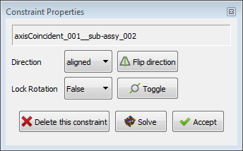
Bei der Erstellung einer Beschränkung wird ein solches Dialogfeld angezeigt, nachdem du eine Schaltfläche in der Beschränkungswerkzeugleiste gedrückt hast:
Oben: Der A2plus Beschränkungseigenschaftsdialog
Bei bestimmten Beschränkungen erlaubt es dir, die Richtung der Beschränkung zu ändern. Mit der Schaltfläche Solve kannst du vorab prüfen, ob diese neue Randbedingung von A2plus gelöst werden kann. Falls nicht, wirf einen Blick auf Abschnitt Fehlerbehebung.
Beschränkungen können durch Ändern der Sichtbarkeit deaktiviert werden. Wähle dazu die Beschränkung in der Baumansicht aus und drücke Space. Dadurch wird die Eigenschaft Daten-EigenschaftSuppressed umgeschaltet. Eine unterdrückte Beschränkung wird bei der Lösung der Baugruppe nicht berücksichtigt.
A2plus bietet die folgenden Beschränkungen:
Punkt auf Punkt
Wähle entweder einen Knoten (Punkt), Kreis oder Kugel auf jedem Teil. Wenn ein Kreis oder eine Kugel ausgewählt wurde, wird dessen Mittelpunkt für die Beschränkung verwendet. Die Werkzeugleistenschaltfläche fügt die Beschränkung pointIdentity hinzu, die die Knoten deckungsgleich werden lässt.
Punkt auf Linie
Wähle einen Knoten (Punkt), oder kreisförmig Kante (wählt seinen Mittelpunkt aus), oder eine sphärische Fläche (wählt auch seinen Mittelpunkt) auf der einen Seite und ein Kante auf dem anderen Teil. Die Werkzeugleistenschaltfläche fügt die Beschränkung pointOnLine hinzu. Dadurch wird der Knoten auf die Kante gesetzt.
Punkt auf Ebene
Wähle einen Knoten (Punkt), oder kreisförmige Kante (wählt seinen Mittelpunkt aus), oder eine sphärische Fläche (wählt auch seinen Mittelpunkt) auf einem Teil und eine Ebene auf dem anderen Teil. Die Werkzeugleistenschaltfläche fügt die Beschränkung pointOnPlane hinzu. Im Dialogfeld Beschränkung kannst du einen Versatz zwischen dem Punkt und der Ebene angeben. Dieser Versatz kann auch zwischen beiden Seiten der Ebene umgedreht werden. Wenn der Versatz gleich Null ist, setzt die Beschränkung den Knoten auf die Ebene.
Kugel auf Kugel
Wähle entweder eine kugelförmige Fläche oder einen Knoten (Punkt) auf beiden Teilen. Die Werkzeugleistenschaltfläche fügt die Beschränkung KugelMitteIdent hinzu. Sie bewirkt, dass entweder das Zentrum der Kugeln, das Zentrum der Kugel und der Knoten oder die Knoten deckungsgleich werden.
Kreiskante auf Kreiskante
Wähle eine kreisförmige Kante bei beiden Teilen aus. Die Schaltfläche fügt die Beschränkung circularEdge hinzu. Der Beschränkungs-Dialog erlaubt Dir einen Versatz zwischen beiden Kanten anzugeben. Der Versatz kann auch umgedreht werden. Du kannst außerdem die Richtung der Beschränkung bestimmen und die Verdrehung der Teile sperren. Wenn der Versatz gleich Null ist, wird die Beschränkung die Kanten konzentrisch in derselben Ebene anordnen.
Achsdeckungsgleich
Wähle entweder eine zylindrische Fläche oder eine lineare Kante auf beiden Teilen. Die Werkzeugleistenschaltfläche fügt die Beschränkung AchseDeckungsgleich hinzu. Der Dialog Beschränkung erlaubt dir die Achsenrichtung anzugeben. Der Dialog ermöglicht es dir außerdem, die Drehung der Teile zu sperren. Durch die Beschränkung werden die Achsen oder Linien deckungsgleich.
Achsparallel
Wähle bei beiden Teilen jeweils entweder eine zylindrische Fläche oder eine lineare Kante aus. Die Schaltfläche fügt die Beschränkung Achsparallel hinzu. Der Dialog dieser Beschränkung erlaubt Dir die Achsrichtung anzugeben. Die Beschränkung setzt die Achsen oder Linien zueinander parallel.
Achse auf Ebene parallel
Wähle entweder ein zylindrisches Fläche oder eine lineare Kante auf einem Teil und eine Ebene auf dem anderen Teil. Die Werkzeugleistenschaltfläche fügt die Beschränkung AchseEbeneParallel hinzu. Die Beschränkung macht die Achse oder Linie parallel zur Ebene.
Achse normal auf Ebene
Wähle entweder ein zylindrisches Fläche oder eine lineare Kante auf einem Teil und eine Ebene auf dem anderen Teil. Die Werkzeugleistenschaltfläche fügt die Beschränkung AchseEbeneNormal hinzu. Durch die Beschränkung wird die Achse oder Linie normal zur Ebene gemacht.
Achse im Winkel zu Ebene
Wähle entweder eine zylindrische Fläche oder eine lineare Kante auf einem Teil und eine Ebene auf dem anderen Teil.Mit der Werkzeugleistenschaltfläche wird die Beschränkung AchseEbeneWinkel hinzugefügt. Die Beschränkung macht die Achse zunächst parallel zur Ebene. Dann kannst du den Winkel für die Achse im erscheinenden Dialogfeld für die Beschränkungseinstellungen anpassen.
Ebene parallel
Wähle eine Ebene auf beiden Teilen aus. Die Werkzeugleistenschaltfläche fügt die Beschränkung EbenenParallel hinzu. Im Dialogfeld Beschränkung kannst du die Richtung der Beschränkung angeben. Durch die Beschränkung werden die Ebenen parallel gemacht.
Ebene auf Ebene
Wähle eine Ebene auf beiden Teilen aus. Die Werkzeugleistenschaltfläche fügt die Beschränkung EbeneDeckungsgleich hinzu. Im Dialogfeld Beschränkung kannst du eine Beschränkungsrichtung und einen Versatz zwischen den Ebenen angeben. Dieser Versatz kann auch umgedreht werden. Wenn der Versatz gleich Null ist, bewirkt die Beschränkung, dass die Ebenen zusammenfallen.
Ebene Winklig
Wähle eine Ebene auf beiden Teilen aus. Die Werkzeugleistenschaltfläche fügt die Beschränkung winkligeEbenen hinzu. Im Dialogfeld Beschränkung kannst du einen Winkel zwischen den Ebenen angeben. Durch die Beschränkung werden die Ebenen zunächst parallel, und der angegebene Winkel wird festgelegt.
Deckungsgleichheit im Massenschwerpunkt
Wähle entweder eine geschlossene Kante oder eine Ebene auf beiden Teilen. Die Werkzeugleistenschaltfläche fügt die Beschränkung Massenschwerpunkt hinzu. Im Dialogfeld Beschränkung kannst du einen Versatz zwischen den Kanten oder Ebenen angeben. Dieser Versatz kann auch umgedreht werden. Außerdem kannst du die Beschränkungsrichtung festlegen und die Drehung der Teile sperren. Wenn der Versatz gleich Null ist, setzt die Beschränkung die Kanten oder Ebenen auf dieselbe Ebene.
Unterbaugruppen
Eine Baugruppe kann andere Baugruppen enthalten. Sie werden wie Teile hinzugefügt, durch drücken der Werkzeugleistenschaltfläche und Wahl einer *.FCStd Datei, die eine Baugruppe enthält. Solche Unterbaugruppen können auch wie Teile bearbeitet werden, indem die Werkzeugleisteschaltfläche
verwendet wird. Bitte stelle bei höheren Baugruppenstufen sicher, dass du die Baugruppe rekursiv über die Werkzeugleistenschaltfläche
aktualisierst, wenn es Änderungen gab.
Handhabung von Beschränkungen
Mögliche Beschränkungen für eine Auswahl werden in der Werkzeugleiste und im Dialogfeld Beschränkungswerkzeuge angezeigt, durch aktivieren der entsprechenden Schaltflächen. Der Beschränkungswerkzeuge Dialog wird über die Werkzeugleistenschaltfläche geöffnet. Es ist beabsichtigt, offen zu bleiben, um der Baugruppe schnell mehrere Beschränkungen hinzufügen zu können.
Vorhandene Beschränkungen können bearbeitet werden, indem sie im Modellbaum ausgewählt und dann entweder doppelt angeklickt oder mit der Werkzeugleistenschaltfläche bearbeitet werden. Dadurch wird das Dialogfeld Beschränkungseigenschaften geöffnet.
Beschränkungen können vorübergehend unterdrückt werden, indem man sie im Modellbaum auswählt und die Baumelementeigenschaft Daten-EigenschaftUnterdrückt ändert.
Beschränkungen können entweder durch Auswahl im Modellbaum und Drücken von Entf oder durch Auswahl eines Teils mit Beschränkungen im Modellbaum und Verwendung der Werkzeugleistenschaltfläche gelöscht werden.
Alle Beschränkungen können jederzeit mit der Werkzeugleistenschaltfläche aufgelöst werden. Wenn die Werkzeugleistenschaltfläche
aktiviert ist, wird nach jeder Bearbeitung einer Beschränkung automatisch eine Auflösung durchgeführt.
Die Werkzeugleistenschaltfläche wirkt sich auf die zuletzt hinzugefügte Beschränkung aus. Sie kehrt die Richtung der Beschränkung um.
Mit dem Werkzeug können vorhandene Beschränkungen angezeigt und überprüft werden. Nach dem Anklicken erscheint ein Dialogfeld. Man wählt dann entweder ein Teil in der Baumstruktur aus und klickt auf die Schaltfläche Aus Part importieren, um alle Beschränkungen dieses Teils abzurufen, oder wählt eine oder mehrere Beschränkungen in der Baumstruktur aus und klickt auf die Schaltfläche Aus der Baumansicht importieren. Als Ergebnis erhält man alle Informationen zu den Beschränkungen. Durch Klicken in die Spalte Unterdrücken (Suppress) kann eine einzelne Beschränkung unterdrückt werden. Weitere Funktionen findetie in den Tooltipps der anderen Dialogschaltflächen.
Stücklisten
Um Stücklisten von Baugruppen zu erstellen, müssen die verschiedenen Teile der Baugruppe Teilinformationen erhalten, die von A2plus gelesen werden können. Dies geschieht durch Bearbeiten des Teils mit Hilfe der Werkzeugleistenschaltfläche . Drücke im geöffneten Teil die Werkzeugleistenschaltfläche
und ein Tabellenblatt mit dem Namen #PARTINFO# wird erstellt.
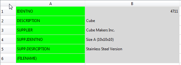
Die Struktur des Tabellenblatts ist wie folgt:
Fülle die grauen Felder mit den Informationen aus, die du hast und in der endgültigen Stückliste haben möchtest.
Verwende in der Baugruppe oder Unterbaugruppe die Werkzeugleistenschaltfläche . Du wirst gefragt, ob du rekursiv über alle Unterbaugruppen iterieren möchtest. Klicke auf Ja. Dadurch wird ein neues Arbeitsblatt mit dem Namen #PARTSLIST# erstellt. Sie enthält die Informationen aus den verschiedenen #PARTSINFO#-Tabellenblättern der Teile in einer Liste wie dieser:
Die Position (POS) wird automatisch entsprechend der Darstellung der Teile im Modellbaum festgelegt. Das oberste Teil erhält die Position 1.
Die Menge (QTY) wird automatisch aus der Baugruppe berechnet. Wenn ein Teil zweimal in der Baugruppe vorkommt, erhält es die Menge 2.
Wenn man eine Teilinfo aktualisiert hat, können die Teileliste durch erneutes Drücken der Symbolleisten-Schaltfläche aktualisiert werden.
Für Unterbaugruppen kann man auch eine Info-Tabelle mit der Symbolleisten-Schaltfläche erstellen. Wenn man die Teileliste der Hauptbaugruppe erstellt oder aktualisiert, werden diese Informationen verwendet, wenn man auf Nein klickt, wenn man gefragt wird, ob man alle Unterbaugruppen rekursiv durchlaufen möchte. Dann sind die verschiedenen Teile nicht in der Teileliste enthalten, sondern nur die Unterbaugruppen.
Sonderfunktionen
Zusammenbaustruktur
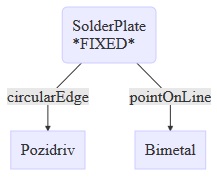
Die Werkzeugleisten-Schaltfläche erstellt eine HTML-Datei mit der Struktur der Baugruppe. Die Datei wird standardmäßig im Ordner der Baugruppendatei erstellt. Die Struktur sieht wie folgt aus:
Freiheitsgrade
Die Schaltfläche kennzeichnet jeden Teil der Baugruppe mit seinen Freiheitsgraden. Außerdem gibt er eine Liste mit allen Teilen und ihren Abhängigkeiten aus. Die Liste wird in FreeCADs Widget Ausgabefenster ausgegeben. Wenn dieses Widget derzeit nicht sichtbar ist, kann es entweder durch einen Rechtsklick auf einen leeren Bereich der FreeCAD-Symbolleiste und anschließende Auswahl im Kontextmenü oder über das Menü Ansicht → Symbolleisten → Ausgabefenster angezeigt werden.
Die Beschriftungen der Anzahl der Freiheitsgrade können mittels eines Klicks auf die Schaltfläche entfernt werden.
Teilkennzeichnungen
Die Schaltfläche kennzeichnet jedes Teil der Baugruppe in der 3D-Ansicht mit seinem Namen. Die Teilekennzeichnungen können durch erneutes Klicken auf die Schaltfläche
wieder entfernt werden.
Form der gesamten Baugruppe
Manchmal ist es notwendig, die gesamte Baugruppe zu einer Form zusammenzufassen. Diese Form kann dann beispielsweise für den 3D-Druck im Arbeitsbereich Mesh oder für Zeichnungen im Arbeitsbereich TechDraw verwendet werden. Sie wird mit der Symbolleisten-Schaltfläche erstellt. Die Form ist standardmäßig nicht sichtbar. Man verwendet dieselbe Symbolleisten-Schaltfläche, um die Form bei Änderungen an der Baugruppe zu aktualisieren.
Absolute Pfade in relative Pfade umwandeln
Mit dem Menü A2plus → Verschiedenes → Absolute Pfade importierter Teile in relative Pfade umwandeln kann man absolute Pfade importierter Teile in relative Pfade umwandeln.
Einstellungen
Die A2plus-Einstellungen können über das FreeCAD-Menü Bearbeiten → Einstellungen und dort im Abschnitt A2plus aufgerufen werden. Die folgenden Optionen können eingestellt werden:
Standardlösungsmethode
- Verwendung der Lösung von Teilsystemen
- Der Löser beginnt mit einem Teil, dessen Eigenschaft Daten-Eigenschaftfixed Position auf true gesetzt ist, und einem daran befestigten Teil. Alle anderen Teile werden nicht berechnet. Wenn eine Lösung gefunden werden konnte, wird das nächste befestigte Teil zur Berechnung hinzugefügt und so weiter.
- Magnetischen Löser verwenden, alle Teile auf einmal lösen
- Der Löser versucht, alle Teile auf einmal in Richtung eines Teils zu bewegen, für das die Eigenschaft Daten-Eigenschaftfixed Position auf true gesetzt ist. Es ist zu beachten, dass dies in den meisten Fällen mehr Zeit für die Berechnung einer Lösung in Anspruch nimmt.
- Feste Position erzwingen
- Hiermit wird die Eigenschaft Daten-Eigenschaftfixed Position für alle Teile in der Baugruppe auf true gesetzt. Dann wird tatsächlich keine Berechnung durchgeführt, da alle Teile immer an den Positionen fixiert sind, an denen sie erstellt wurden.
Standardlöserverhalten
- Automatisch lösen, wenn eine Beschränkungseigenschaft geändert wird
- Der Löser wird automatisch gestartet. Entspricht dem Aktivieren der Symbolleisten-Schaltfläche.
.
Verhalten beim Aktualisieren importierter Teile
- Importierte Teile vor der Aktualisierung neu berechnen
- Alle Teile der Baugruppe, einschließlich Unterbaugruppen, werden in FreeCAD geöffnet, um anhand der Werte aus den Tabellenkalkulationen neu konstruiert zu werden. Diese Funktion dient der vollständig parametrischen Konstruktion. Hinweis: Diese Funktion ist sehr experimentell und wird für wichtige Projekte nicht empfohlen.
Bekannte Probleme:
- Die Baugruppe kann aufgrund falscher Verweise auf topologische Namen in Teilen zerstört werden.
- Master-Tabellen können beschädigt werden, wenn sie bearbeitet werden, während eine referenzierte Teiledatei bereits geschlossen ist. Dies kann zum Absturz von FreeCAD führen.
- Rekursive Aktualisierung importierter Teile aktivieren
- Öffnet alle Unterbaugruppen rekursiv, um sie zu aktualisieren.
- Experimentelle topologische Benennung verwenden
- Beim Importieren von Teilen in die Baugruppe generiert ein Algorithmus topologische Namen für jedes Unterelement der importierten Form. Die topologischen Namen werden in die Daten-Eigenschaftmux Info geschrieben. Wenn ein importiertes Teil aktualisiert werden muss, werden diese topologischen Namen verwendet, um die Unterelemente der Beschränkungen zu aktualisieren. Dadurch werden Baugruppen robuster gegenüber volatilen Unterelementnummern von FreeCAD.
Hinweis: Dies erhöht die Dateigrößen und die Berechnungszeit beim Importieren von Teilen. Wenn die topologische Benennung verwendet werden soll, muss sie vor dem Erstellen der Baugruppe aktiviert werden.
- Transparenz pro Fläche von Teilen und Baugruppen übernehmen
- Verwendet die Farb- und Transparenzeinstellungen aus importierten Teilen.
Hinweis: Diese Funktion ist sehr experimentell und wird für wichtige Projekte nicht empfohlen.
- Unsichtbare Formen nicht importieren
- Dadurch werden unsichtbare Bezugs-/Konstruktionsformen ausgeblendet. Hinweis: Es dürfen keine Beschränkungen mit Bezugs-/Konstruktionsformen in übergeordneten oder anderen Unterbaugruppen verbunden sein. Andernfalls kann die Baugruppe beschädigt werden.
Die Volumenvereinigung zum Importieren von Teilen und Unterbaugruppen verwenden: Alle importierten Teile werden direkt als Vereinigung zusammengefügt. Diese Funktion ist nützlich für FEM-Simulationen oder 3D-Druck, wenn nur ein Volumen zulässig ist. Alternativ kann später eine Form der gesamten Baugruppe erstellt werden.
Benutzeroberflächeneinstellungen
- Beschränkungen in der Symbolleiste anzeigen
- Wenn diese Option nicht verwendet wird, sind die Symbolleisten-Schaltflächen für die verschiedenen Beschränkungen nicht sichtbar, um Platz in der Symbolleiste zu sparen. Neue Beschränkungen können weiterhin über das Dialogfeld Beschränkungswerkzeuge (Symbolleisten-Schaltfläche
) festgelegt werden.
- Native Dateiverwaltung des Betriebssystems verwenden
- Wenn diese Option verwendet wird, wird bei der Auswahl von Dateien für Baugruppen der Dateidialog des Betriebssystems angezeigt.
Speicherung von Dateien
- Use relative paths for imported parts
- Verwendet relative Dateipfade zu den Teiledateien.
- Use absolute paths for imported parts
- Verwendet absolute Dateipfade zu den Teiledateien.
- All files are in this project folder
- Alle Projektdateien müssen sich im angegebenen Ordner befinden. Es spielt keine Rolle, ob sie sich in Unterordnern dieses Ordners befinden. Hinweis: Keine Datei darf mehrfach im Ordner vorhanden sein (z. B. in verschiedenen Unterordnern).
Diese Option ist hilfreich, wenn man an verschiedenen Rechnern arbeitet, da man dann nur den Projektordner kopieren muss.
Problembehebung
Früher oder später wird man auf das Problem stoßen, dass A2plus die festgelegten Einschränkungen nicht lösen kann. Um dies zu überwinden, gibt es verschiedene Strategien:
Verwendung des Konfliktfinderwerkzeugs
Dies ist die sicherste Methode, wenn man mehrere Einschränkungen hat, da dieses Werkzeug versucht, eine Einschränkung nach der anderen zu lösen, bis es die widersprüchliche Einschränkung findet. Anschließend kann man mit den anderen Strategien fortfahren, um die identifizierte Einschränkung zu beheben. Das Werkzeug wird über die Schaltfläche in der Symbolleiste aufgerufen. .
Überprüfung der Beschränkungsrichtung
Manchmal scheinen Beschränkungen konsistent definiert zu sein, können aber dennoch nicht gelöst werden. Ein Beispiel: Angenommen, man hat eine planesParallel-Beschränkung für zwei Ebenen festgelegt. Nun möchte man für dieselben Ebenen die Beschränkung planeCoincident festlegen, was A2plus jedoch nicht lösen kann. In diesem Fall unterscheiden sich die Beschränkungsrichtungen von planesParallel und planeCoincident. Man verwendet für beide Beschränkungen dieselbe Richtung, um dieses Problem zu beheben.
A2plus bietet die Möglichkeit, mithilfe der Symbolleisten-Schaltfläche automatisch die richtige Ausrichtung für alle Beschränkungen der Baugruppe zu überprüfen.
Löschen von Beschränkungen
Die meisten Fälle von unlösbaren Benschränkungen treten direkt beim Hinzufügen einer neuen Benschränkung auf. Die Lösung besteht dann darin, die zuletzt hinzugefügte Benschränkung zu löschen. A2plus wird dies ebenfalls vorschlagen.
Manchmal ist die Löschstrategie die einzige Möglichkeit, beispielsweise wenn man einen Teil in FreeCAD so bearbeitet hat, dass Flächen oder Kanten, die mit Beschränkungen verbunden sind, fehlen. Man sollte dann jeweils eine Beschränkung löschen, die mit dem geänderten Teil verbunden ist. Man verwendet nach jedem Löschvorgang die Schaltfläche in der Symbolleiste, um zu überprüfen, ob man einen lösbaren Zustand erreicht hat.
Wenn man eine Baugruppe hat, die gelöst werden kann, fügt man Schritt für Schritt die erforderlichen Beschränkungen hinzu.
Bewegliche Teile
In einigen Fällen benötigt der Löser lediglich bessere Startwerte, um die Einschränkungen zu lösen. Nehmen wir beispielsweise den Fall, dass man ein Achsteil und ein Radteil hat. Man fügt eine axisCoincident -Beschränkung hinzu und erhält keine Information, dass der Löser fehlgeschlagen ist, aber die Teile werden nicht entsprechend verschoben, und im Widget "Ausgabefenster" von FreeCAD sieht man "REACHED POS-ACCURACY :0.0". Eine Lösung hierfür besteht darin, die Teile näher an die Position zu verschieben, die man mit der Beschränkung erreichen möchte.
Hinweis: Sicherstellen, dass mindestens ein Teil der Beschränkung die Eigenschaft Daten-Eigenschaftfixed Position auf false gesetzt aufweist.
Festlegen der Eigenschaft Spitze
Wenn man nach dem Import in eine A2plus-Baugruppe einige Funktionen des Teils vermisst, überprüft man die Eigenschaft Daten-EigenschaftTip.
A2plus importiert Körper von Teilen mit allen ihren Merkmalen bis zum obersten Merkmal. Dies ist sinnvoll, da die Einstellung der Spitze auf ein bestimmtes Merkmal bedeutet, dass alle Merkmale hinter der Spitze nicht im endgültigen Teil erscheinen sollten. Wenn man also ein Teilemerkmal in A2plus vermisst, öffnet man das Teil über die Symbolleisten-Schaltfläche und wählt einen Körper aus, um dessen Eigenschaft Daten-EigenschaftTip anzuzeigen. Befindet sich die Spitze nicht an der gewünschten Stelle, klickt man mit der rechten Maustaste auf das Merkmal, an dem die Spitze sein soll, und wählt
Spitze setzen. Abschließend speichert man das Teil und lädt die Baugruppe mit der Symbolleisten-Schaltfläche
neu.
Baugruppenbaum reparieren
Wenn man keinen eindeutigen Grund dafür sieht, warum bestimmte Einschränkungen nicht behoben werden können, kann man versuchen, die Symbolleisten-Schaltfläche zu verwenden. Dadurch werden alle Einschränkungen behoben und die Teile erneut unter den verschiedenen Teilen gruppiert.
Migration alter A2plus Baugruppen
Mit A2plus vor März 2019 erstellte Baugruppen zeigen nicht die richtigen Symbole für importierte Teile und haben veraltete Eigenschaften. Diese Baugruppen können mit dem Menü A2plus → Verschiedenes → Proxys importierter Teile migrieren auf A2plus Version 0.4.35 und neuer migriert werden. Anschließend müssen die Baugruppendatei gespeichert und erneut geöffnet werden.
Vermeidung von Sonderzeichen
Diese Strategie ist für Windows nicht erforderlich.
Auf einigen Betriebssystemen können Probleme auftreten, wenn die Dateinamen oder Dateipfade von Teilen oder Baugruppen Akzentzeichen enthalten. Daher solche Zeichen und generell Sonderzeichen vermeiden.
Festlegen der Position
Diese Strategie ist für Baugruppen, die mit A2plus 0.3.11 oder neuer erstellt wurden, nicht mehr erforderlich, da A2plus nun eine Warnung für fehlende feste Positionen ausgibt.
Wenn man eine Beschränkung zwischen zwei Teilen festlegt und kein Teil die Eigenschaft Daten-Eigenschaftfixed Position auf true gesetzt hat oder durch eine Beschränkung mit einem Teil verbunden ist, bei dem Daten-Eigenschaftfixed Position auf true gesetzt ist, kann die Beschränkung nicht gelöst werden. Das Gleiche geschieht, wenn bei beiden Teilen der Beschränkung Daten-Eigenschaftfixed Position auf true gesetzt ist.
Dann gibt A2plus die Informationen über die fehlgeschlagene Lösung aus, aber manchmal sieht man nur, dass die Teile nicht entsprechend verschoben wurden, und im Widget Ausgabefenster von FreeCAD wird "REACHED POS-ACCURACY :0.0" angezeigt. Das bedeutet, dass der Löser ohne Fehler abgeschlossen wurde, aber die Einschränkungen tatsächlich nicht lösen konnte.
Daher wird überprüft, ob bei mindestens einem der Teile in der Baugruppe Daten-Eigenschaftfixed Position auf „true” gesetzt ist. Dann sicherstellen, dass nur Beschränkungen für ein Teil festgelegt werden, das in irgendeiner Weise mit dem festen Teil verbunden ist. Um diese Abhängigkeiten zu visualisieren, siehe Abschnitt Baugruppenstruktur.
Drehende Teile
Diese Strategie ist für Baugruppen, die mit A2plus 0.4.0 oder neuer erstellt wurden, nicht mehr erforderlich, da A2plus die Teile nun automatisch im Hintergrund ein wenig dreht, um einen ausreichenden Startwinkel für den Löser zu erhalten.
Der Löser schlägt häufig bei der Einschränkung angledPlanes fehl, wenn die beiden ausgewählten Ebenen derzeit einen Winkel von 0° oder 180° haben. (Die Teile werden nicht entsprechend verschoben und im Widget Ausgabefenster von FreeCAD wird "REACHED POS-ACCURACY :0.0" angezeigt.) Eine Lösung hierfür besteht darin, ein Teil mit der Transformationsfunktion von FreeCAD um einige Grad zu drehen (Rechtsklick auf das Teil im Modellbaum und Auswahl von Transform im Kontextmenü).
Hinweis: Sicherstellen, dass mindestens ein Teil der Beschränkung die Eigenschaft Daten-Eigenschaftfixed Position auf false gesetzt aufweist.
Animation
A2plus bietet Animationen per Drag & Drop und über Python-Skripte.
Ziehen
Zieh-Animationen sind interaktiv, da man sie durch Ziehen eines Teils der Baugruppe auslösen kann. So erhält man diese Art von Animationen:
- Das Teil vollständig beschränken, dessen Bewegung oder Drehung animiert werden soll.
- Auf die Schaltfläche
in der Symbolleiste klicken. Dadurch wird der Ziehmodus aktiviert.
- Auf das gewünschte Teil in der Baugruppe klicken.
- Jetzt kann man die Maus bewegen, und das Teil folgt der Bewegung der Maus innerhalb der definierten Beschränkungen.
- Um den Ziehmodus zu beenden, klickt man mit der linken Maustaste in die Baugruppe oder drückt die ESC-Taste.
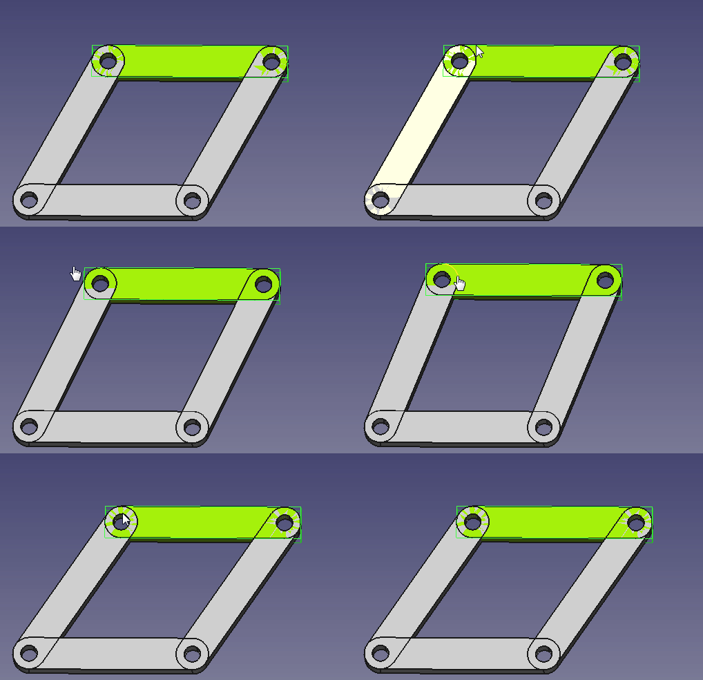
Hier ist ein Beispiel für eine Baugruppe, mit der die Ziehanimation ausprobiert werden kann: A2p_example-for-dragging-animation.FCStd
Oben: Die Zieh-Animation unter Verwendung der Beispielbaugruppe
Skripten
Obwohl der Ziehen-Modus schöne interaktive Animationen bietet, sind diese manchmal für Screencasts oder Videos nicht präzise genug. Skriptbasierte Animationen haben den Vorteil, dass sie Bewegungen und Drehungen auf definierte Weise animieren. Man kann beispielsweise ein Teil um genau 10° vor und zurück drehen. Die folgenden Beispiele verwenden eine Baugruppe, in der ein Teil gedreht werden soll. Wenn man versucht, dies mit dem Ziehen-Modus zu animieren, wird man feststellen, wie schwierig es ist, eine Vor- und Rückwärtsdrehung zu erzielen, die man beispielsweise dem Chef in einer Präsentation zeigen könnte. Mit dem interaktiven Beispielskript ist dies jedoch eine leichte Aufgabe.
Eine skriptgesteuerte Animation funktioniert in der Regel wie folgt:
- Die Baugruppe ist vollständig eingeschränkt
- Das Skript ändert einen Parameter, beispielsweise die Position oder den Drehwinkel eines Teils
- Nach der Parameteränderung werden die Baugruppeneinschränkungen gelöst
- Schritt 2 und 3 werden wiederholt, um die Animation zu erhalten
Es ist auch möglich, anstelle eines Platzierungs-Parameters eine Beschränkung zu ändern, beispielsweise den Abstand zwischen zwei Ebenen.
Einfaches Skriptbeispiel
Die einfachste Art, eine Animation zu programmieren, ist eine nicht interaktive Animation, die einer definierten Bewegung folgt. Hier ein Beispiel: Lade zunächst diese Assembly-Datei herunter.: A2p_animated-example.FCStd und auch dieses Python-Skript: A2p_animation-example-script.py.
Dies ist der Inhalt des Skripts, und die mit einem '#' beginnenden Zeilen beschreiben, was die verschiedenen Skriptzeilen bewirken:
# Bibliotheken importieren
import time, math, PySide
import A2plus.a2p_solversystem as a2p_solver

# wir verwenden Schritte von 1 Grad
step = 1
# warte zwischen jedem Schritt 1 ms
timeout = 0.001
# der Anfangswinkel beträgt 0 Grad
angle = 0
# wir nehmen das aktuell geöffnete Dokument
document = FreeCAD.activeDocument()
# wir möchten später den Drehwinkel des Teils "star_wheel_001" ändern.
starWheel = document.getObject("star_wheel_001")
# einen Fortschrittsdialog definieren, der von 0 bis 360 läuft.
progressDialog = PySide.QtGui.QProgressDialog(u"Animation progress", u"Stop", 0, 360)

# Der while-Block ist die Hauptschleife, um den Winkel zu ändern und anschließend
# die Baugruppenbeschränkungen zu lösen.
while angle < 360: # run this loop until we have one full turn (360 degrees)
    # den Drehwinkel vergrößern
    angle += step
    # den neuen Winkel im Fortschrittsdialog festlegen
    progressDialog.setValue(angle)
    # den Drehwinkel des Teils "star_wheel_001" ändern
    starWheel.Placement.Rotation.Angle = math.radians(angle)
    # die Beschränkungen lösen
    a2p_solver.solveConstraints(document, useTransaction=True)
    # die Ansicht nach der Lösung aktualisieren („Gui” steht für „grafische Benutzeroberfläche”)
    FreeCADGui.updateGui()
    # den Fortschrittsdialog in den Vordergrund bringen
    PySide.QtGui.QWidget.raise_(progressDialog)
    # wenn im Dialogfeld "Stopp" gedrückt wurde, die Schleife beenden
    if progressDialog.wasCanceled():
        angle = 360
    # etwas warten, bevor der nächsten Schritt ausgeführt wird
    time.sleep(timeout)
Um die Animation mit dem Skript auszuführen, muss
- Die Baugruppendatei in FreeCAD geöffnet werden.
- Die Skriptdatei in FreeCAD geöffnet werden.
- Auf die Schaltfläche
 in der Symbolleiste geklickt werden, um das Skript (auch Makro genannt) auszuführen.
 - Zur Registerkarte der Baugruppe gewechselt werden, um die Drehung zu sehen.
Um zu üben, ändert man einfach etwas im Skript und führt es anschließend aus. Man erhöht beispielsweise step auf 5.
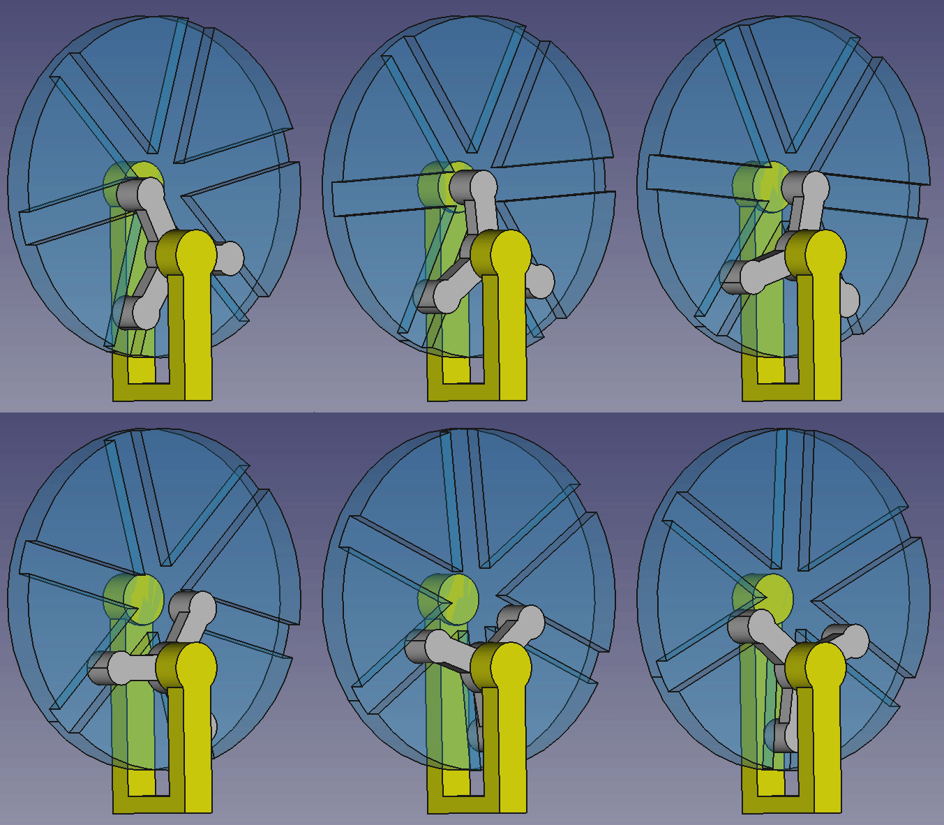
Dies ist das Ergebnis der Beispielanimation:
Interaktives Skriptbeispiel
Das erste Skriptbeispiel zeigte, wie man eine Animation ohne Benutzerrückmeldung erstellt. Bei den meisten Anwendungen muss man mit der Animation interagieren. Das Interessante an diesem Beispiel ist beispielsweise, zu sehen, wie die Antriebsstifte die mittlere Nut des Rades überqueren. Um sich das genauer anzusehen, möchte man dieses Detail vielleicht dem Kollegen oder dem Chef zeigen. Daher benötigt man eine interaktive Lösung.
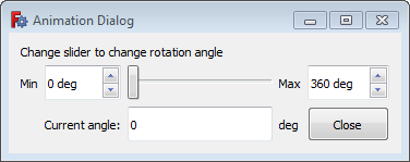
Dies kann mithilfe eines benutzerdefinierten Animationsdialogs mit einem Schieberegler erfolgen. Durch Verschieben des Schiebereglers kann man den Drehwinkel einstellen und so an interessanten Positionen hin und her drehen.
Wir verwenden dieselbe Assembly-Datei: A2p_animated-example.FCStd und dieses Python-Skript: A2p_animation-example-script.py.
Dies ist der Inhalt des Skripts, um den interaktiven Animationsdialog aufzurufen:
# Bibliotheken importieren
import time, math, PySide, sys
import FreeCAD.A2plus.a2p_solversystem as a2p_solver
from FreeCAD import Units
from PySide import QtCore, QtGui

# Nach jeder Berechnung 1 ms warten
timeout = 0.001
# wir nehmen das aktuell geöffnete Dokument
document = FreeCAD.activeDocument()
# wir möchten später den Drehwinkel des Teils "star_wheel_001" ändern
starWheel = document.getObject("star_wheel_001")

class AnimationDlg(QtGui.QWidget): # Der Animations-Dialog

    def __init__(self): # to initialize the dialog
        super(AnimationDlg, self).__init__()
        self.initUI()

    def initUI(self): # the definition of the dialog components
        self.setMinimumSize(self.minimumSizeHint()) # set the minimal dialog size to minimum
        self.setWindowTitle('Animation Dialog')
        # use a grid layout for the whole form
        self.mainLayout = QtGui.QGridLayout()
        self.lineNo = 0 # first dialog grid line
        # add description label
        DescriptionLabel = QtGui.QLabel(self)
        DescriptionLabel.setText("Change slider to change rotation angle")
        self.mainLayout.addWidget(DescriptionLabel,self.lineNo,0,1,4)
         # next dialog grid line
        self.lineNo += 1
        # add a label; there is no need for the "self." prefix because we don't want to change the label later
        LabelMin = QtGui.QLabel(self)
        LabelMin.setText("Min")
        LabelMin.setFixedHeight(32)
        self.mainLayout.addWidget(LabelMin,self.lineNo,0)
        # add a spin edit to define the slider minimum
        self.MinEdit = QtGui.QSpinBox(self)
        # get the angle unit as string
        self.MinEdit.setSuffix(" " + str(FreeCAD.Units.Quantity(1, FreeCAD.Units.Angle))[2:])
        self.MinEdit.setMaximum(999)
        self.MinEdit.setMinimum(0)
        self.MinEdit.setSingleStep(10)
        self.MinEdit.setValue(0)
        self.MinEdit.setFixedHeight(32)
        self.MinEdit.setToolTip("Minimal angle for the slider")
        QtCore.QObject.connect(self.MinEdit, QtCore.SIGNAL("valueChanged(int)"), self.setMinEdit)
        self.mainLayout.addWidget(self.MinEdit,self.lineNo,1)
        # add the slider
        self.slider = QtGui.QSlider(QtCore.Qt.Horizontal, self)
        self.slider.setRange(0, 360)
        self.slider.setValue(0)
        self.slider.setFixedHeight(32)
        self.slider.setToolTip("Move the slider to change the rotation angle")
        QtCore.QObject.connect(self.slider, QtCore.SIGNAL("sliderMoved(int)"), self.handleSliderValue)
        self.mainLayout.addWidget(self.slider,self.lineNo,2)
        # add a label
        LabelMax = QtGui.QLabel(self)
        LabelMax.setText("Max")
        LabelMax.setFixedHeight(32)
        self.mainLayout.addWidget(LabelMax,self.lineNo,3)
        # add a spin edit to define the slider maximum
        self.MaxEdit = QtGui.QSpinBox(self)
        # get the angle unit as string
        self.MaxEdit.setSuffix(" " + str(FreeCAD.Units.Quantity(1, FreeCAD.Units.Angle))[2:])
        self.MaxEdit.setMaximum(999)
        self.MaxEdit.setMinimum(1)
        self.MaxEdit.setSingleStep(10)
        self.MaxEdit.setValue(360)
        self.MaxEdit.setFixedHeight(32)
        self.MaxEdit.setToolTip("Maximal angle for the slider")
        QtCore.QObject.connect(self.MaxEdit, QtCore.SIGNAL("valueChanged(int)"), self.setMaxEdit)
        self.mainLayout.addWidget(self.MaxEdit,self.lineNo,4)
         # next dialog grid line
        self.lineNo += 1
        # add a spacer
        self.mainLayout.addItem(QtGui.QSpacerItem(10,10), 0, 0)
        # add a label
        LabelCurrent = QtGui.QLabel(self)
        LabelCurrent.setText("Current angle:")
        LabelCurrent.setFixedHeight(32)
        self.mainLayout.addWidget(LabelCurrent,self.lineNo,1)
        # output the current angle
        self.CurrentAngle = QtGui.QLineEdit(self)
        self.CurrentAngle.setText(str(0))
        self.CurrentAngle.setFixedHeight(32)
        self.CurrentAngle.setToolTip("Current rotation angle")
        self.CurrentAngle.isReadOnly()
        self.mainLayout.addWidget(self.CurrentAngle,self.lineNo,2)
        # add label for the unit
        LabelUnit = QtGui.QLabel(self)
        LabelUnit.setText("deg")
        LabelUnit.setFixedHeight(32)
        self.mainLayout.addWidget(LabelUnit,self.lineNo,3)
        # button to close the dialog
        self.Close = QtGui.QPushButton(self)
        self.Close.setText("Close")
        self.Close.setFixedHeight(32)
        self.Close.setToolTip("Closes the dialog")
        QtCore.QObject.connect(self.Close, QtCore.SIGNAL("clicked()"), self.CloseClicked)
        self.mainLayout.addWidget(self.Close,self.lineNo,4)
        # place the defined grid layout to the dialog
        self.setLayout(self.mainLayout)
        self.update()

    def handleSliderValue(self):
        # Schiebereglerwert als Winkel festlegen
        starWheel.Placement.Rotation.Angle = math.radians(self.slider.value())
        # aktuellen Winkel ausgeben
        self.CurrentAngle.setText(str(self.slider.value()))
        # Beschränkungen lösen
        a2p_solver.solveConstraints(document)
        # die Ansicht nach der Lösung aktualisieren ('Gui' stands for 'graphical user interface')
        FreeCADGui.updateGui()
        # etwas warten, damit genügend Zeit für die Berechnungen bleibt
        time.sleep(timeout)

    def setMinEdit(self):
        # sicherstellen, dass das Minimum kleiner ist als das Maximum
        if self.MinEdit.value() >=  self.MaxEdit.value():
            self.MaxEdit.setValue(self.MinEdit.value() + 1)
        self.slider.setRange(self.MinEdit.value(), self.MaxEdit.value())

    def setMaxEdit(self):
        # sicherstellen, dass das Minimum kleiner ist als das Maximum.
        if self.MinEdit.value() >=  self.MaxEdit.value():
            self.MinEdit.setValue(self.MaxEdit.value() - 1)
        self.slider.setRange(self.MinEdit.value(), self.MaxEdit.value())

    def CloseClicked(self):
        AnimationDialog.close()

# Erstellen und Anzeigen des definierten Dialogfelds
AnimationDialog = AnimationDlg()
AnimationDialog.show()

# diese Schleife ausführen, wenn das Dialogfeld sichtbar ist
while AnimationDialog.isVisible():
    # die Ansicht aktualisieren; wichtig, um dem Betriebssystem Feedback zu geben, dass der Dialog aktiv ist
    FreeCADGui.updateGui()
    # Dialogfeld in den Vordergrund bringen, damit es immer sichtbar ist
    QtGui.QWidget.raise_(AnimationDialog)
    # auch hier den Wert des Schiebereglers ausgeben, da der Schieberegler während der Berechnung möglicherweise verschoben wurde
    AnimationDialog.CurrentAngle.setText(str(AnimationDialog.slider.value()))
Der im Skript definierte Dialog sieht wie folgt aus:
Skriptbefehle
Um die Skriptsyntax besser zu verstehen, findet man hier einige Informationen zu den Befehlen:
starWheel.Placement.Rotation.Angle = math.radians(angle)
Hier ändern wir die Positionierungseigenschaft Rotation.Angle des zuvor als starWheel erhaltenen Teils. Diese Eigenschaft erhält den Winkel als Radiant (Einheit). Die Funktion radians() aus der Bibliothek math konvertiert den Winkel von Grad in Radiant.
Die Eigenschaft Rotation.Angle verwendet die aktuelle Positionierungsachse des Teils (in unserem Beispiel die X-Achse). Um das Teil beispielsweise um die Z-Achse zu drehen, kann man die Drehachse (vor dem Aufruf des Drehbefehls) mit dem folgenden Befehl festlegen:
starWheel.Placement.Rotation.Axis = FreeCAD.Vector(0,0,1)
Anstelle des Drehens können Teile auch verschoben werden. Um beispielsweise die Position des Rades in Y-Richtung zu ändern, lautet der Befehl:
starWheel.Placement.Base.y = PositionShift
In diesem Fall würden wir nicht die Variable angle definieren, sondern PositionShift, die wir bei jedem Durchlauf der Schleife ändern.
Es gibt verschiedene Möglichkeiten, die Positionierung eines Teils festzulegen. Einige davon sind hier dokumentiert. Leider gibt es (noch) keine Liste mit allen möglichen Positionierungsbefehlen.
a2p_solver.solveConstraints(document, useTransaction=False/True)
Dies ist ein A2plus-spezifischer Befehl. Er löst die Baugruppenbeschränkungen der Baugruppe, die wir zuvor als document erhalten haben. Die Option useTransaction legt fest, ob FreeCAD jede Änderung im Undo/Redo-Stack speichern soll. Bei großen Animationen kann man diese Option daher auf false setzen.
- Erste Schritte
- Installation: Herunterladen, Windows, Linux, Mac, Zusätzliche Komponenten, Docker, AppImage, Ubuntu Snap
- Grundlagen: Über FreeCAD, Graphische Oberfläche, Mausbedienung, Auswahlmethoden, Objektname, Voreinstellungseditor, Arbeitsbereiche, Dokumentstruktur, Objekteigenschaften, FreeCAD unterstützen, Spenden
- Hilfe: Anleitungen, Videoanleitungen
- Arbeitsbereiche: Std Base, Arch, Assembly, BIM, CAM, Draft, FEM, Inspection, Material, Mesh, OpenSCAD, Part, PartDesign, Points, Reverse Engineering, Robot, Sketcher, Spreadsheet, Surface, TechDraw, Test Framework
