Macro WorkFeatures/de
|
|
| Beschreibung |
|---|
| Werkzeug Dienstprogramm zum Erstellen von Punkten, Achsen, Ebenen...und andere nützliche Funktionen. Versionsmakro : 05/2019 Datum der letzten Änderung : 01.05.2019 FreeCAD version : Alle Herunterladen : Werkzeugleisten-Symbol Autor: rentlau_64 |
| Autor |
| rentlau_64 |
| Herunterladen |
| Werkzeugleisten-Symbol |
| Links |
| Makros Rezepte Wie man Makros installiert Symbolleisten anpassen |
| Macro-Version |
| 05/2019 |
| Datum der letzten Änderung |
| 01.05.2019 |
| FreeCAD-Version(s) |
| Alle |
| Standardverknüpfung |
| None |
| Siehe auch |
| None |
Beschreibung
Werkzeug-Dienstprogramm zum Erstellen von:
- Punkten (Mittelpunkte, Kreismittelpunkte, Mittelpunkte von Objekten...),
- Achsen (aus zwei Punkten, Normalen von Ebenen...),
- Ebenen (aus drei Punkten, aus einer Achse und einem Punkt...)
- Und viele andere nützliche Funktionen, die einem die Erstellung eines Projekts erleichtern. Dieses Dienstprogramm befindet sich in der Combo-Ansicht mit der Bezeichnung Work Features (Deutsch: ArbeitsFunktionen).

WorkFeatures
Anwendungen
ArbeitsFunktionen
-
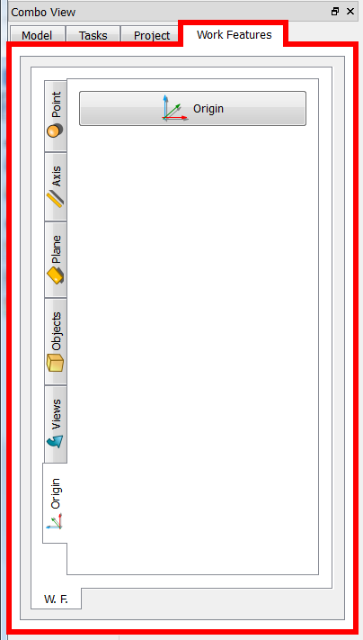 Nach dem Aktivieren der ArbeitsFunktionen bewegt sich das Werkzeug in der Combo-Ansicht des Fensters nach links.
 -
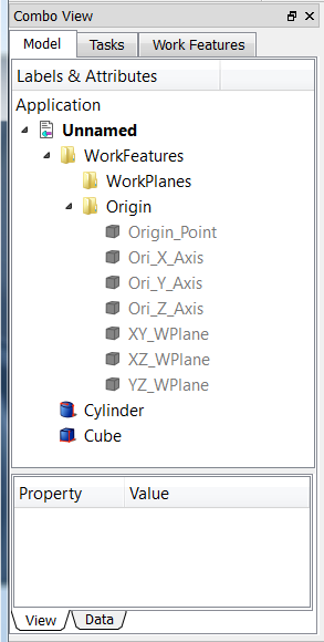 Jede Verwendung und jedes Tag, das einer Funktionsgruppe entspricht, ist eine Gruppe, die im Namen des verwendeten Kennzeichens erstellt wurde. Der Ursprung von Achse, Punkt und Ebene wird direkt auf ausgeblendet gesetzt.
 -
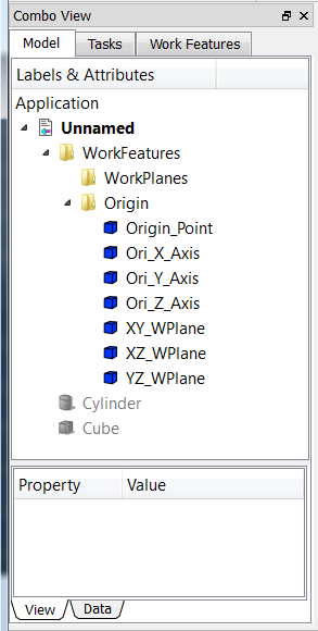 Es können allgemeine Befehle EINGEBEN UND VERWENDET werden, um die erstellte Funktion sichtbar zu machen.
Beispieltaste Leertaste oder ein Objekt auswählen und Rechtsklick mit der Maus und auf „Auswahl ausblenden“ oder „Auswahl anzeigen“ klicken.


Reiter Origin (Ursprung)
 |
|
Reiter Points (Punkte)
 |
|
Reiter Axis (Achsen)
 |
|
Reiter Plane (Ebene)
 |
|
Reiter Objects (Objekte)
 |
|
Reiter Views (Ansichten)
 |
|
Reiter Modif. (Modifizieren)
 |
|
Reiter Check. (Überprüfen)
 |
|
Skript
Nach dem Herunterladen der komprimierten Datei von hier
Werkzeugleistensymbol 
Herunterladen der neusten Version auf GitHub , muss die ZIP-Datei entpackt werden und alle Dateien in das Makroverzeichnis kopiert werden.
PS: Dieses Makro befindet sich noch in der Entwicklung. Diese Seite bitte regelmäßig besuchen, um sicher zu sein, dass man die neueste Version erhält.

Den ![]() Addon-Manager Menü → Werkzeuge → Addon-Manager zur einfachen Installation von ArbeitsFunktionen und anderen interessanten Makros verwenden.
Addon-Manager Menü → Werkzeuge → Addon-Manager zur einfachen Installation von ArbeitsFunktionen und anderen interessanten Makros verwenden.
Hier geht es zur ausführlichen Anleitung zur Installation von Makros.
Beispiele
Schneidwerkzeuge
Einstellung der Schneidwerkzeuge (Cutting tools): Ein zu schneidendes Objekt, eine Schnittlinie und eine Referenzebene wählen. Winkel ist ein Winkel zwischen der Schneidebene und der Referenzebene. Dicke ist die Breite der Schnittebene.


Praktisches Beispiel ausführen
-
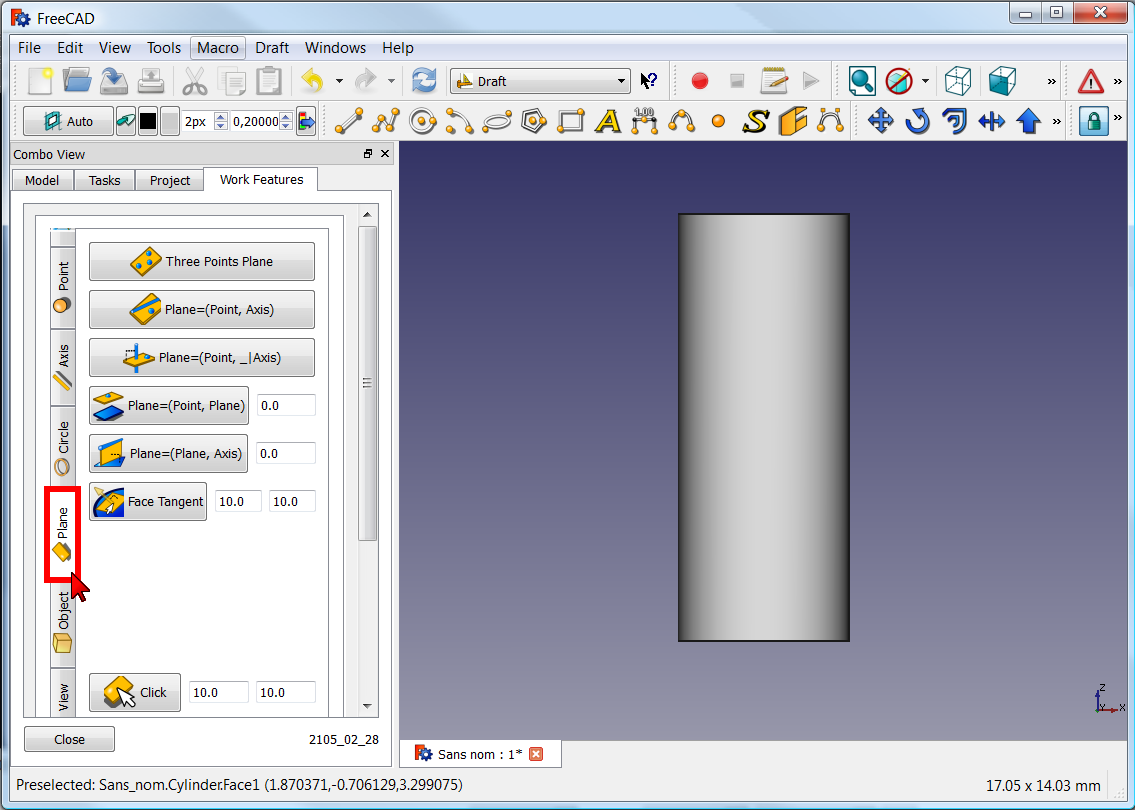 Reiter Plane (Ebene) auswählen
 -
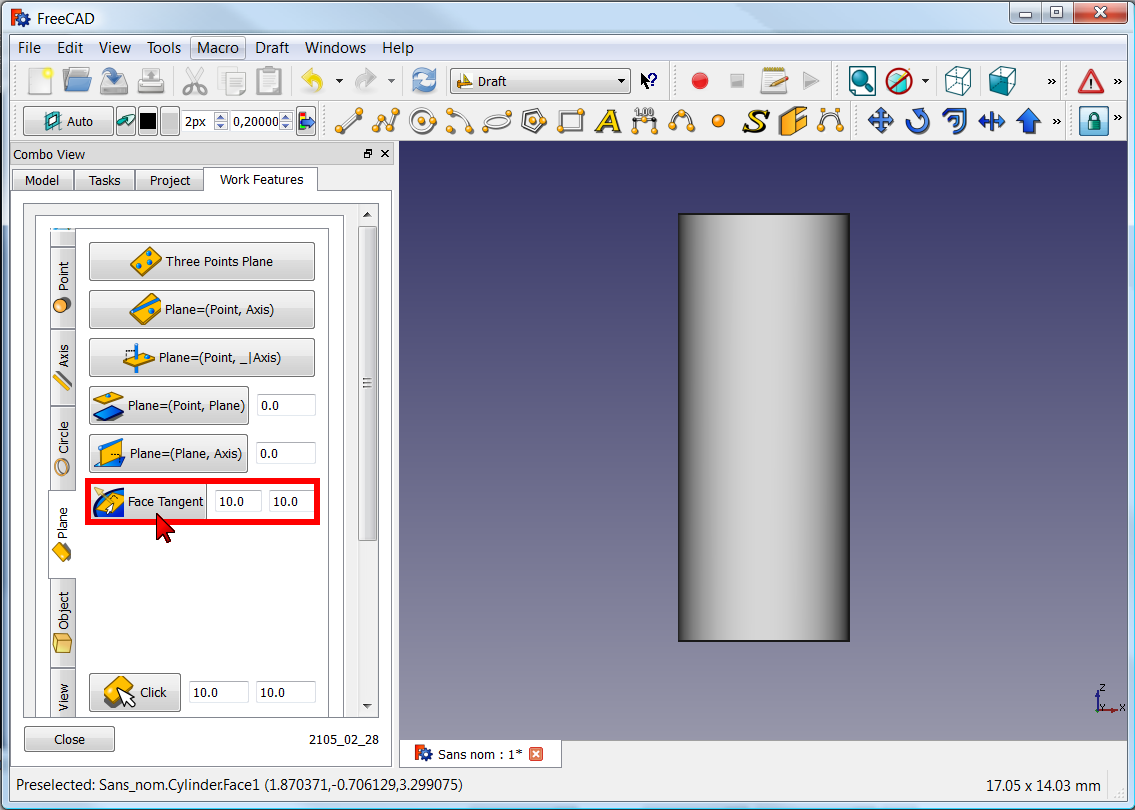 und die Schaltfläche Plane drücken
(Die Abmessungen der Ebene können geändert werden (Standard: 10 x 10)).


-
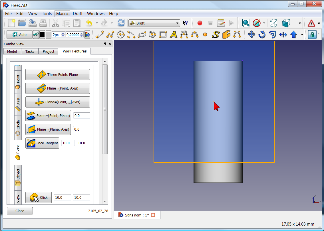 Das Arbeitsobjekt anklicken. Die Ebene wird tangential zum Objekt (hier ein Zylinder) erstellt.
 -
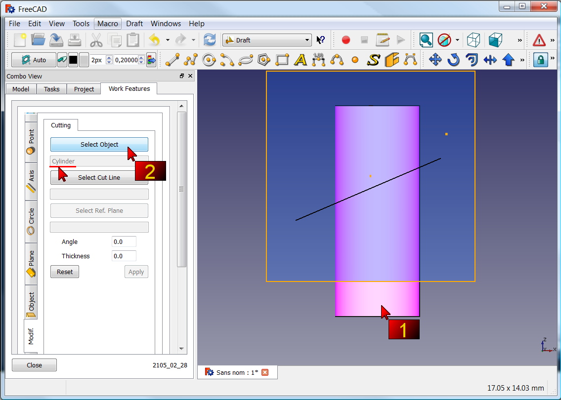 Den Reiter Modif. klicken, und
1 : auf das Objekt klicken, um es auszuschneiden.
2 : die Schaltfläche Select object klicken (hier wird der Zylinder und dann der Name angezeigt)


-
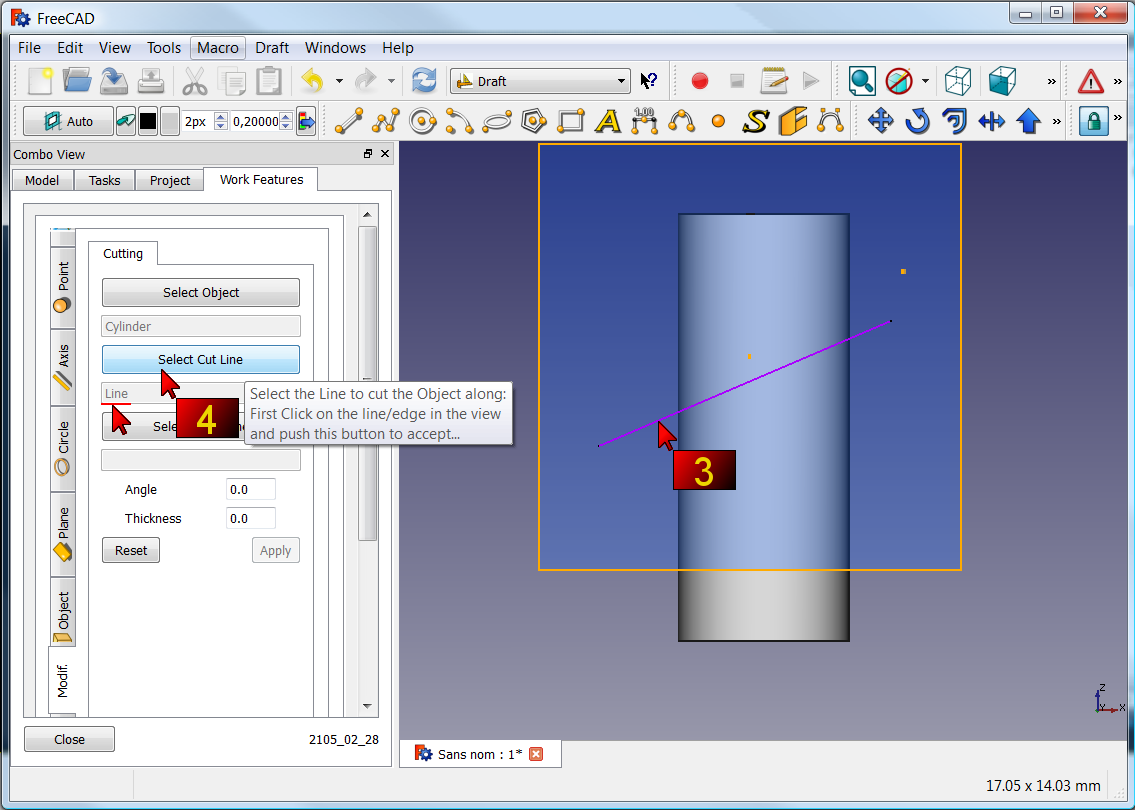 3 : auf die Linie klicken, um den Zylinder zu schneiden.
4 : die Schaltfläche Select Cut Line klicken (der Name wird angezeigt) -
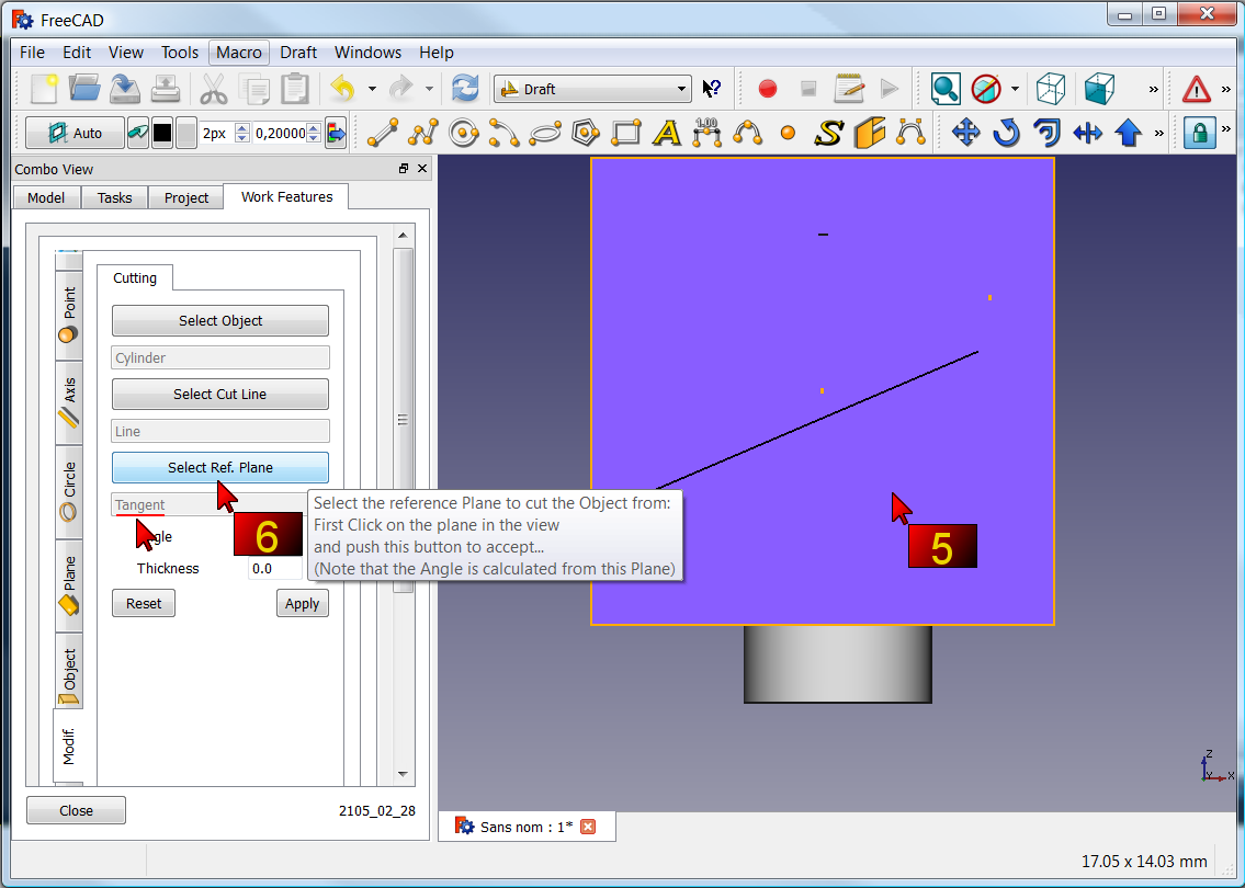 5 : die Arbeitsebene anklicken
6 : die Schaltfläche Select Ref. Plane klicken (der Name wird angezeigt)


-
 die Schaltfläche Apply drücken
 -
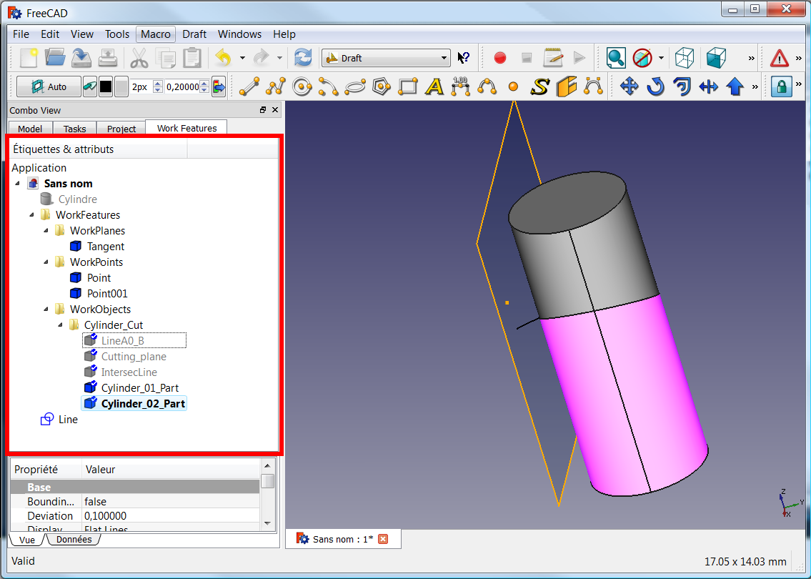 Die Bearbeitung ist abgeschlossen und alle Bearbeitungen sind erhalten geblieben.


-
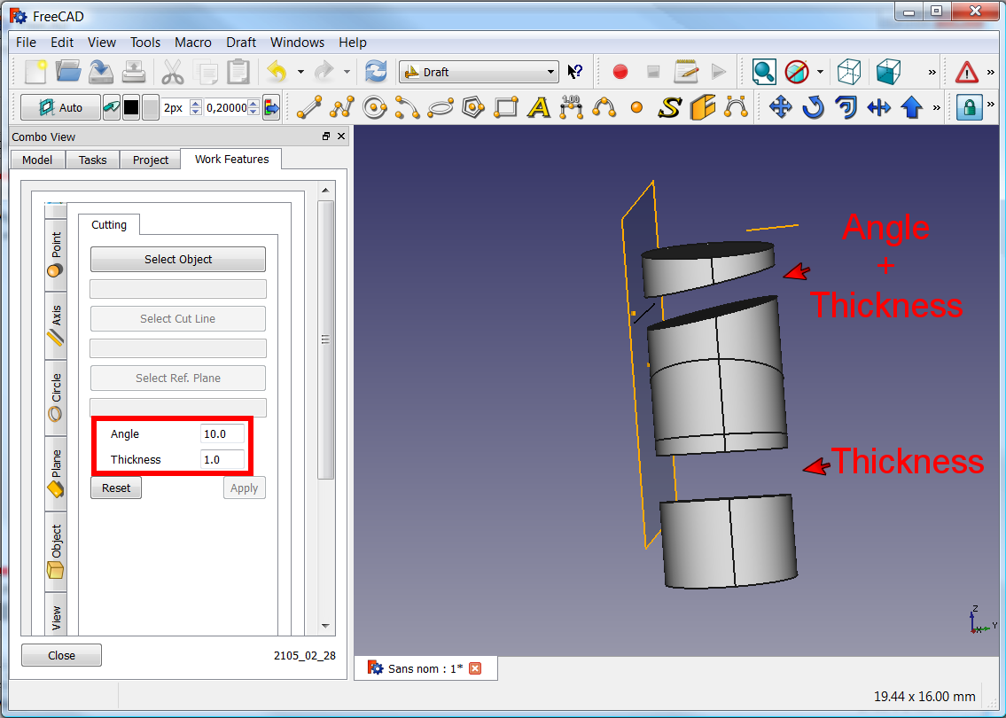 Der Winkel und die Dicke für den Schnitt können ebenfalls angegeben werden.

Konzentrische Beschränkung zwischen zwei nicht zylindrischen Teilen

| Wie eine Beschränkung zwischen zwei nicht zylindrischen Teilen hergestellt wird. 1 : Das zu ändernde Originalobjekt. 2 : Zielmitte zweier Vierkantrohre. 3 : Das erste Objekt auswählen und im Menü Achse 1/2 auf "Objekt(e)" X-, Y-, Z-Axen klicken. 4 : Gleiche Vorgehensweise für das zweite Objekt. 5 : Auf die Schaltfläche Draw style klicken und auf „Wireframe“ klicken, 6 : zur Verdeutlichung der Ansicht. 7 : Das zu zentrierende Objekt und seine erstellte Achse wählen. 8 : Auf die Schaltfläche Draft Move klicken 9 : und die erste Achse wählen, die auf der zweiten Achse verschoben werden soll. 10 : Normalenansicht mit der Schaltfläche Draw style und auf As iswiederherstellen. 11 : Das erste verschobene Objekt anklicken und die Position mit "Combo-Ansicht > Daten > Positionierung" korrigieren. 12 : Das von ArbeitsFunktionen erstellte Objekt (contener axis) auswählen und löschen. 13 : Das Objekt verschwindet. 14 : Das Ergebnis. |
Rotationsobjekt
-
 Click the image for see the animation.

Ebene auf Flächentangente
-
 Click the image for see the animation.
Click the object, click the Face tangent button, click the point on face for create the plane.

Verweise
Die Forumsdiskussion MACRO:Work Feature 2014_12
Neueste Version
Symbole :

Quellen :
Auf GitHub : /github.com/Rentlau/WorkFeature-WB.git
Datum 2019-05-01 (YYYY-MM-DD)
20/01/2019
08/03/2015 : WF_2015_03_08 - Kreisschnitt hinzugefügt - Sind parallel, sind senkrecht, sind koplanar hinzugefügt
17/02/2015 : WF_2015_02_17 - Reiter Kreis und Ellipse hinzugefügt - Reiter Schneiden hinzugefügt
25/01/2015 : WF_2015_01_25.zip Objekt Zylinder Würfel hinzugefügt
18/01/2015 : WF_2015_01_18.tar.gz Ebene und Fläche zur Ansicht hinzufügen
28/12/2014 : WorkFeatures_2014_12_28.zip
27/12/2014 : WF_2014_12_27.zip
- Erste Schritte
- Installation: Herunterladen, Windows, Linux, Mac, Zusätzliche Komponenten, Docker, AppImage, Ubuntu Snap
- Grundlagen: Über FreeCAD, Graphische Oberfläche, Mausbedienung, Auswahlmethoden, Objektname, Voreinstellungseditor, Arbeitsbereiche, Dokumentstruktur, Objekteigenschaften, FreeCAD unterstützen, Spenden
- Hilfe: Anleitungen, Videoanleitungen
- Arbeitsbereiche: Std Base, Arch, Assembly, BIM, CAM, Draft, FEM, Inspection, Material, Mesh, OpenSCAD, Part, PartDesign, Points, Reverse Engineering, Robot, Sketcher, Spreadsheet, Surface, TechDraw, Test Framework