Macro Draft Circle 3 Points/it
| Descrizione |
|---|
| Crea un cerchio da 3 punti selezionati. Versione macro: 01.00 Ultima modifica: 2013-03-11 Versione FreeCAD: All Download: ToolBar Icon Autore: Mario52 |
| Autore |
| Mario52 |
| Download |
| ToolBar Icon |
| Link |
| Raccolta di macro Come installare le macro Personalizzare la toolbar |
| Versione macro |
| 01.00 |
| Data ultima modifica |
| 2013-03-11 |
| Versioni di FreeCAD |
| All |
| Scorciatoia |
| Nessuna |
| Vedere anche |
| Nessuno |
Description
Descrizione
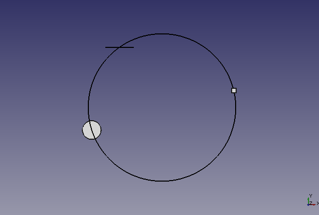
Questa macro crea un cerchio da 3 punti selezionati. I punti possono essere oggetti quali cubi o cilindri, quindi le coordinate selezionate saranno il centro di queste forme.
crea un cerchio da 3 punti selezionati.
Usage
Utilizzo
Selezionare 3 punti o forme nella vista 3D poi avviare la macro. Se la forma è una linea, le coordinate sono date dal centro della linea.
Options
Opzioni
Se gli oggetti selezionati sono su piani diversi, (xy Z10, xy Z2, xy Z5) il cerchio sarà costruito sul piano Z=0 (x,y Z=0).
Se tutti gli oggetti selezionati hanno la stessa coordinata Z (xy Z5, xy Z5, xy Z5), cerchio sarà costruito nel piano di Z (x,y Z=5).
Script
Draft_Circle_3_Points.FCMacro
# -*- coding: utf-8 -*-
# créer un cercle à partir de 3 points sélectionnés sur le plan X,Y
# 04/03/2013
# la formule provient de
# http://www-obs.univ-lyon1.fr/labo/fc/Ateliers_archives/ateliers_2005-06/cercle_3pts.pdf
# lire la note dans le pdf, sur l'ordre de sélection des points,
# si la formule renvoie une erreur (exemple les 3 points dans le même alignement)
#
import Draft, Part, FreeCAD, math, PartGui, FreeCADGui
from math import sqrt, pi, sin, cos
from FreeCAD import Base

# prendre les objets sélectionnés
sel = FreeCADGui.Selection.getSelection()
i=0
centreX=0
centreY=0
rayon=0
# S'il y a 3 points sélectionnés alors..
if len(sel)==3 :
	i=0
	ta=[0,0,0,0,0,0,0,0,0]
	for obj in sel:
		x=(obj.Shape.BoundBox.Center)
		ta[i+0]=(x.x)
		ta[i+1]=(x.y)
		ta[i+2]=(x.z)
		i=i+3
# Affectation des variables
	x_point_1=ta[0]
	y_point_1=ta[1]
	z_point_1=ta[2]

	x_point_2=ta[3]
	y_point_2=ta[4]
	z_point_2=ta[5]

	x_point_3=ta[6]
	y_point_3=ta[7]
	z_point_3=ta[8]
# Calcul des coordonnées du centre du cercle
	centreX =((x_point_3**2-x_point_2**2+y_point_3**2-y_point_2**2)/(2*(y_point_3-y_point_2))-(x_point_2**2-x_point_1**2+y_point_2**2-y_point_1**2)/(2*(y_point_2-y_point_1)))/((x_point_3-x_point_2)/(y_point_3-y_point_2)-(x_point_2-x_point_1)/(y_point_2-y_point_1))
	centreY =-(x_point_2-x_point_1)/(y_point_2-y_point_1)*centreX+(x_point_2**2-x_point_1**2+y_point_2**2-y_point_1**2)/(2*(y_point_2-y_point_1))
	rayon =sqrt((x_point_1-centreX)**2+(y_point_1-centreY)**2)
# Définition de la coordonnée Z
# Si toutes les coordonnées Z sont égales le centreZ s'aligne à la coordonnée Z
	if z_point_1==z_point_2 and z_point_2==z_point_3:
		centreZ=z_point_1
	else:
# Si une coordonnée est différente alors Z=0
		centreZ=0
# Création du cercle
	pl=FreeCAD.Placement()
	pl.Rotation.Q=(0.0,-0.0,-0.0,1.0)
	pl.Base=FreeCAD.Vector(centreX,centreY,centreZ)
	Draft.makeCircle((rayon),placement=pl,face=False,support=None)
# Affiche le résultat dans la Vue rapport de FreeCAD
	FreeCAD.Console.PrintMessage("Coordonnée X : "+str(centreX)+"\r\n")
	FreeCAD.Console.PrintMessage("Coordonnée Y : "+str(centreY)+"\r\n")
	FreeCAD.Console.PrintMessage("Coordonnée Z : "+str(centreZ)+"\r\n")
	FreeCAD.Console.PrintMessage("Rayon        : "+str(rayon  )+"\r\n")
else:
# Si la condition n'est pas remplie, recommencer
	FreeCAD.Console.PrintError("Sélectionnez 3 points et recommencez\r\n")
Improved version
Versione migliorata
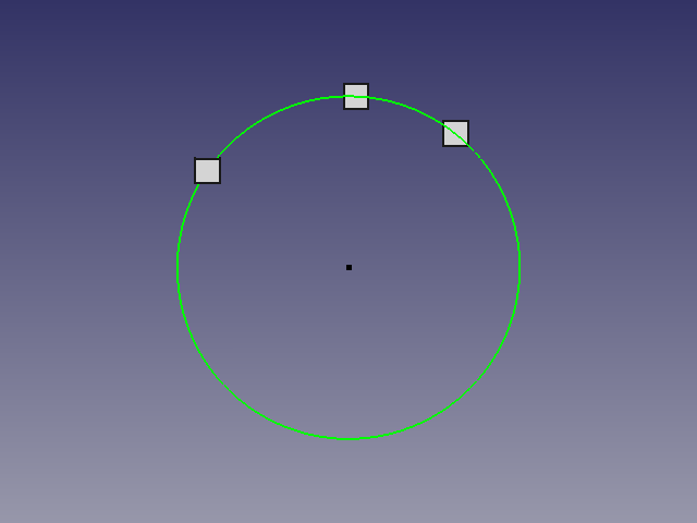
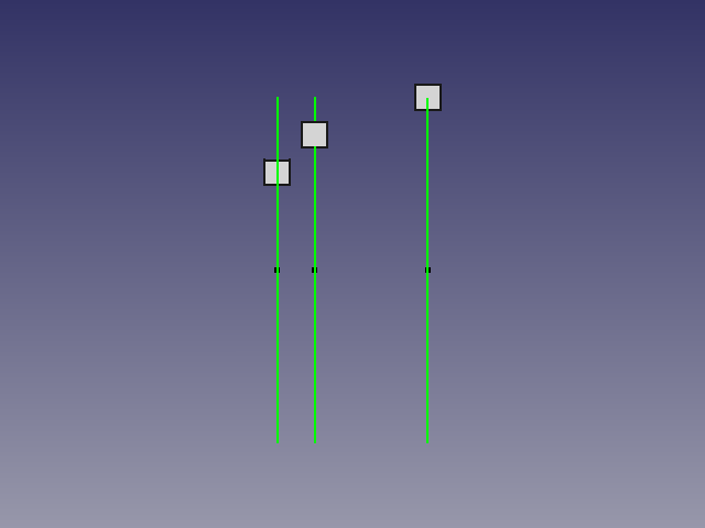
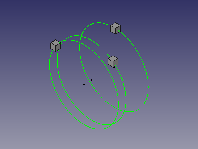
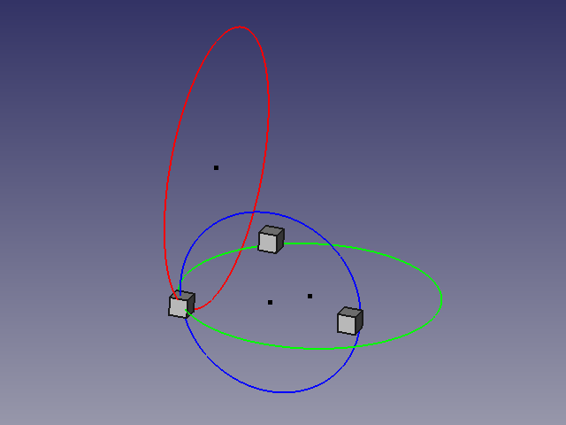
In aggiunta alle caratteristiche precedenti, questo esempio serve per costruire un cerchio in posizione ortogonale su ciascuna forme selezionate, e sul piano XY, YZ, XZ scelto.
Il cerchio assume il colore dell'asse a cui si riferisce, indipendentemente dal colore corrente, e può essere disegnato il centro del cerchio (opzione O/N).
-
Cercle circonscrit sur 3 formes,
-
de manière orthogonale sur la forme choisie
-
-
Le impostazioni da modificare.
# Change the values here below
			# mode by default vueChoix = 0 and alignerSur = 0
	vueChoix=0	# choice of the top view = 1 XY, view Front = 2 ZX, Right view = 3 ZY
	alignerSur=0	# Aligns the circle shaped the choice (1,2 or 3) or Z = 0
	afficherPoint=1	# Displays the center point of the circle
# -*- coding: utf-8 -*-
# créer un cercle à partir de 3 points séléctionnés
# avec comme options le cercle peut être construit sur un plans au choix
# à la coordonnée d'une des trois formes sélectionnées au choix
# et création du point central O/N
# 04/03/2013 , 07/09/2018 replace PyQt4 to PySide
# la formule provient de
# http://www-obs.univ-lyon1.fr/labo/fc/Ateliers_archives/ateliers_2005-06/cercle_3pts.pdf
# lire la note dans le pdf, sur l'ordre de sélection des points,
# si la formule renvoie une erreur (exemple les 3 points dans le même alignement)
#
import Draft, Part, FreeCAD, math, PartGui, FreeCADGui
from math import sqrt, pi, sin, cos
from FreeCAD import Base
from PySide import QtCore, QtGui

def errorDialog(msg):
    # Create a simple dialog QMessageBox
    # The first argument indicates the icon used: one of QtGui.QMessageBox.{NoIcon, Information, Warning, Critical, Question}
	diag = QtGui.QMessageBox(QtGui.QMessageBox.Critical,u"Error Message",msg)
	diag.setWindowModality(QtCore.Qt.ApplicationModal)
	diag.exec_()

def affiche(x,y,z,rayon,r,v,b,afficherPoint):
	pl.Base=FreeCAD.Vector(x,y,z)
	Draft.makeCircle((rayon),placement=pl,face=False,support=None)
	FreeCADGui.activeDocument().activeObject().LineColor = (r,v,b)
	if afficherPoint==1:
		Draft.makePoint(x,y,z)
	diag = QtGui.QMessageBox(QtGui.QMessageBox.Information,u"Coordinates",u"Coordinates X : "+str(x)+"\r\n"+u"Coordinates Y : "+str(y)+"\n"+u"Coordinates Z : "+str(z)+"\nRayon\t     : "+str(rayon))
	diag.setWindowModality(QtCore.Qt.ApplicationModal)
	diag.exec_()

# prendre les objets selectionnes
sel = FreeCADGui.Selection.getSelection()
i=0
centreX=0;centreY=0;rayon=0

# S'il y a 3 points sélectionnés alors..
if len(sel)==3 :
	i=0
	ta=[0,0,0,0,0,0,0,0,0]
	for obj in sel:
		x=(obj.Shape.BoundBox.Center)
		ta[i+0]=(x.x)
		ta[i+1]=(x.y)
		ta[i+2]=(x.z)
		i=i+3
# Change the values here below
			# mode by default vueChoix = 0 and alignerSur = 0
	vueChoix=0	# choice of the top view = 1 XY, view Front = 2 ZX, Right view = 3 ZY
	alignerSur=0	# Aligns the circle shaped the choice (1,2 or 3) or Z = 0
	afficherPoint=1	# Displays the center point of the circle

    # Affectation des variables
	if vueChoix==3:		# View of right ZY (Red)
 	  	z_point_1=ta[0]
		x_point_1=ta[1]
		y_point_1=ta[2]

		z_point_2=ta[3]
		x_point_2=ta[4]
		y_point_2=ta[5]

		z_point_3=ta[6]
		x_point_3=ta[7]
		y_point_3=ta[8]

	elif vueChoix==2:	# Front view ZX (Green)
 	  	y_point_1=ta[0]
		z_point_1=ta[1]
		x_point_1=ta[2]

		y_point_2=ta[3]
		z_point_2=ta[4]
		x_point_2=ta[5]

		y_point_3=ta[6]
		z_point_3=ta[7]
		x_point_3=ta[8]

	else:			# Top view XY (blue)
 	  	x_point_1=ta[0]
		y_point_1=ta[1]
		z_point_1=ta[2]

		x_point_2=ta[3]
		y_point_2=ta[4]
		z_point_2=ta[5]

		x_point_3=ta[6]
		y_point_3=ta[7]
		z_point_3=ta[8]

    # Calculation of coordinates of the center of the circle
	try:
		centreX =((x_point_3**2-x_point_2**2+y_point_3**2-y_point_2**2)/(2*(y_point_3-y_point_2))-(x_point_2**2-x_point_1**2+y_point_2**2-y_point_1**2)/(2*(y_point_2-y_point_1)))/((x_point_3-x_point_2)/(y_point_3-y_point_2)-(x_point_2-x_point_1)/(y_point_2-y_point_1))
		centreY =-(x_point_2-x_point_1)/(y_point_2-y_point_1)*centreX+(x_point_2**2-x_point_1**2+y_point_2**2-y_point_1**2)/(2*(y_point_2-y_point_1))
		rayon =sqrt((x_point_1-centreX)**2+(y_point_1-centreY)**2)
	except:
		errorDialog(u"Impossible calculation too aligned elements")
	else:
	#finally: sera TOUJOURS exécuté
	   # Definition of the coordinate Z
		centreZ=0
	    # Création du cercle
		pl=FreeCAD.Placement()
		if vueChoix==1:	# Plan XY Dessus
			pl.Rotation.Q=(0,0,0,1.0)
			if alignerSur==1:
				affiche(centreX,centreY,z_point_1,rayon,0.0,0.0,1.0,afficherPoint)
			elif alignerSur==2:
				affiche(centreX,centreY,z_point_2,rayon,0.0,0.0,1.0,afficherPoint)
			elif alignerSur==3:
				affiche(centreX,centreY,z_point_3,rayon,0.0,0.0,1.0,afficherPoint)
		elif vueChoix==2: # Plan XZ Face
			pl.Rotation.Q=(1,0,0,1.0)
			if alignerSur==1:
				affiche(centreY,z_point_1,centreX,rayon,0.0,1.0,0.0,afficherPoint)
			elif alignerSur==2:
				affiche(centreY,z_point_2,centreX,rayon,0.0,1.0,0.0,afficherPoint)
			elif alignerSur==3:
				affiche(centreY,z_point_3,centreX,rayon,0.0,1.0,0.0,afficherPoint)
		elif vueChoix==3: # Plan YZ Droite
			pl.Rotation.Q=(0,1,0,1.0)
			if alignerSur==1:
				affiche(z_point_1,centreX,centreY,rayon,1.0,0.0,0.0,afficherPoint)
			elif alignerSur==2:
				affiche(z_point_2,centreX,centreY,rayon,1.0,0.0,0.0,afficherPoint)
			elif alignerSur==3:
				affiche(z_point_3,centreX,centreY,rayon,1.0,0.0,0.0,afficherPoint)
		else:	# modifier pour avoir XYZ
			# si les coordonnées Z sont égales alors le cercle s'aligne à Z
			if z_point_1==z_point_2 and z_point_2==z_point_3:
				centreZ=z_point_1
				affiche(centreX,centreY,z_point_1,rayon,0.0,0.0,0.0,afficherPoint)
			else:
	        	# Si une coordonnée est différente alors Z=0
				affiche(centreX,centreY,0,rayon,0.0,0.0,0.0,afficherPoint)

else:
    # Si la condition n'est pas remplie, recommencer
	errorDialog(u"Select 3 points and repeat")
	#FreeCAD.Console.PrintError("Select 3 points and repeatr\n")
Anaglyphe
Anaglifo
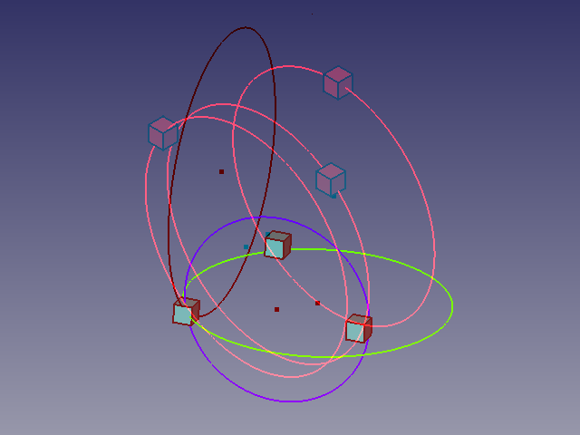
Utilizzando occhiali con filtri rosso e ciano, in questo anaglifo è possibile vedere due diverse posizioni ![]() .
.
Guarda alternativamente con l'occhio sinistro e l'occhio destro per vedere le viste separatamente.
Credits
Crediti
La genesi della macro Draft Circle 3 Points si trova nel forum (PYTHON) coordonnées d'un point a cui ha contribuito flachyjoe che ringrazio.
La formula è presa da cercle_3pts.pdf ed utilizzata con il gentile permesso del suo autore.
