FrameForge Workbench/pl

Introduction
FrameForge is dedicated to creating Frames and Beams, and apply operations (miter cuts, trim cuts) to theses profiles.
The tutorial below is also available on GitHub.
Tutorial
Create the skeleton
Beams are attached to edges (from a sketch for instance) or Parametric Lines. For a start, we are going to create a simple frame.
-
In a new file, switch to the FrameForge workbench.
-
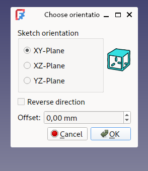
Create a sketch, and specify the XY orientation.
-
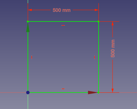
Draw a simple square in the sketch. This will be our skeleton.
-
Close Sketch edit mode.
Create the frame
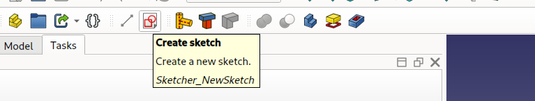
-
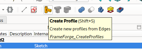
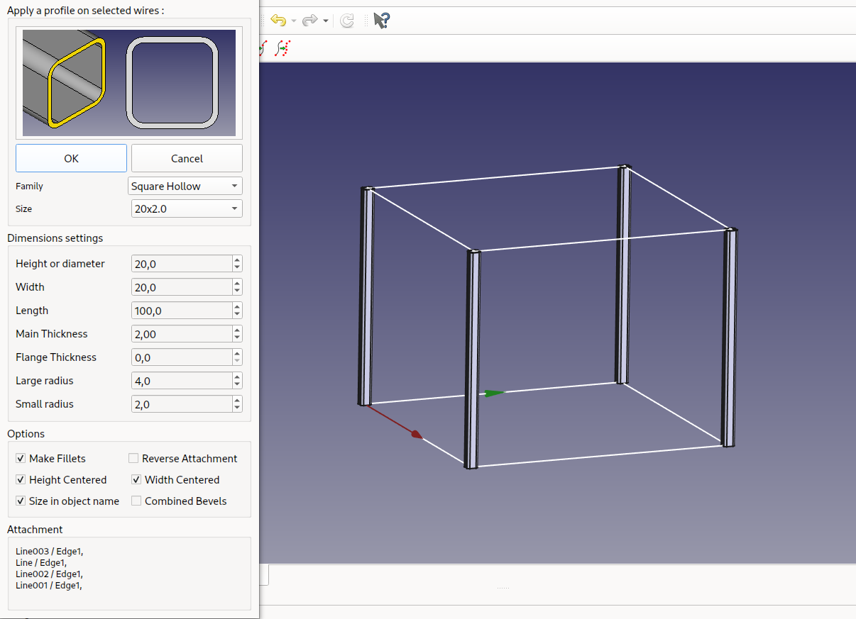
Launch the Create Profile tool.
-
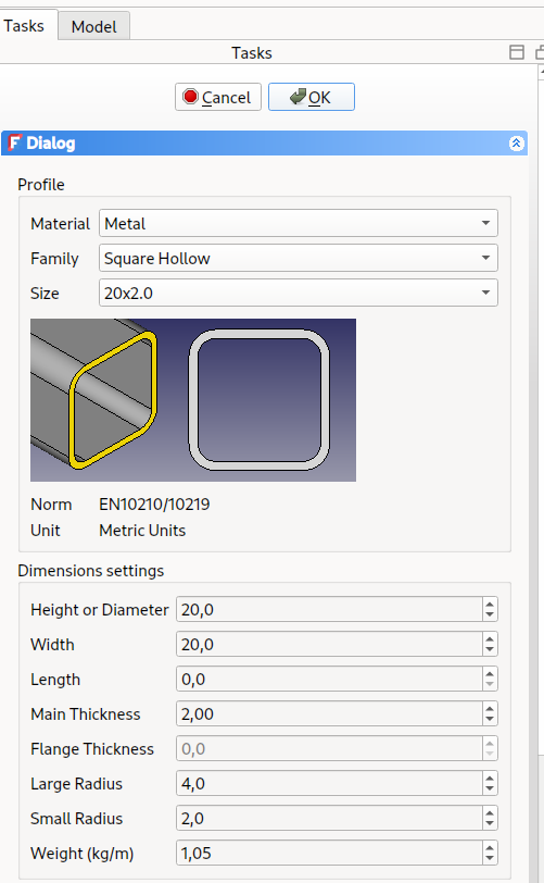
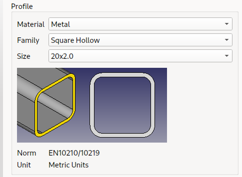
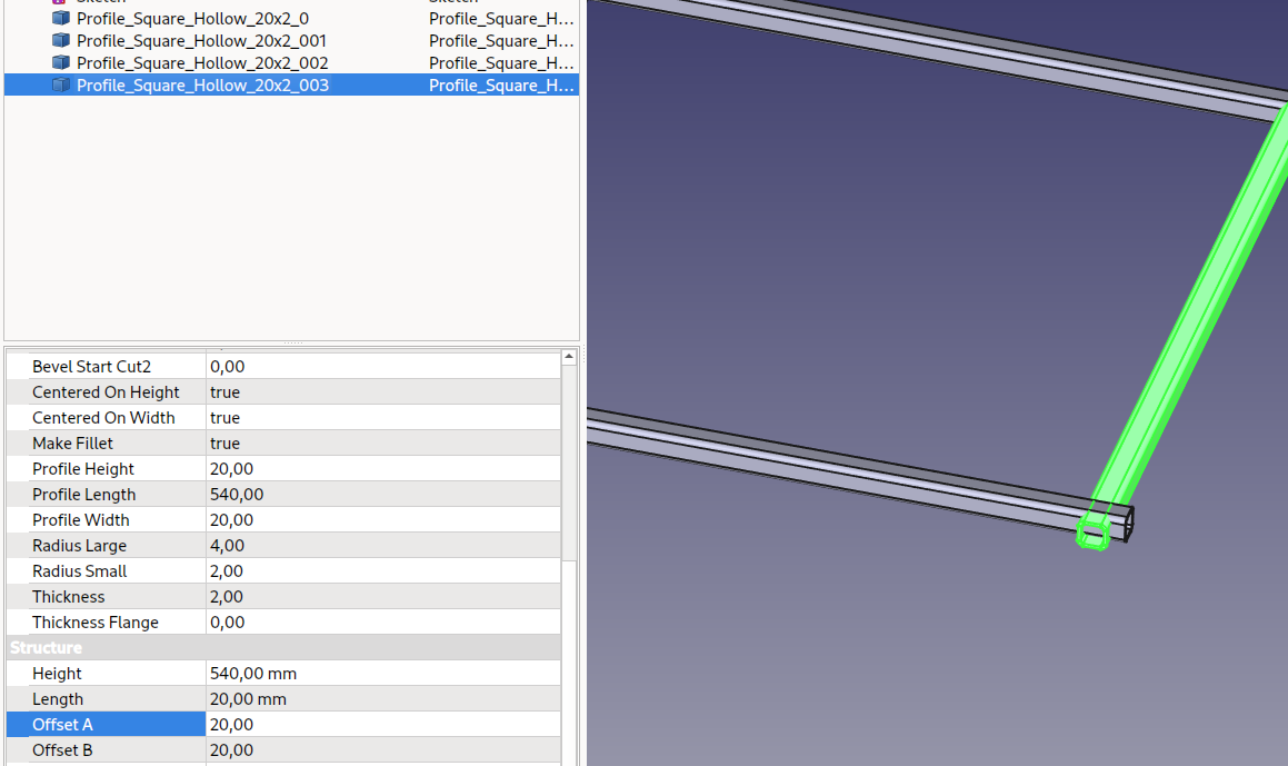
Select a profile from the lists (Material / Family / Size). You can change the size just below the family, the tool has a lot of predefined profiles, you can also change the parameters.
-
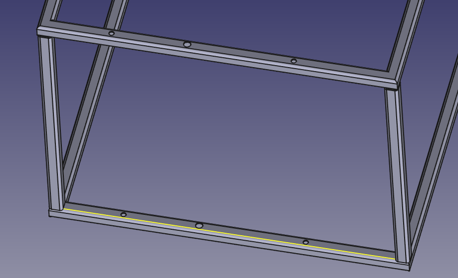
In the 3D View, select the edges to apply the profile to.
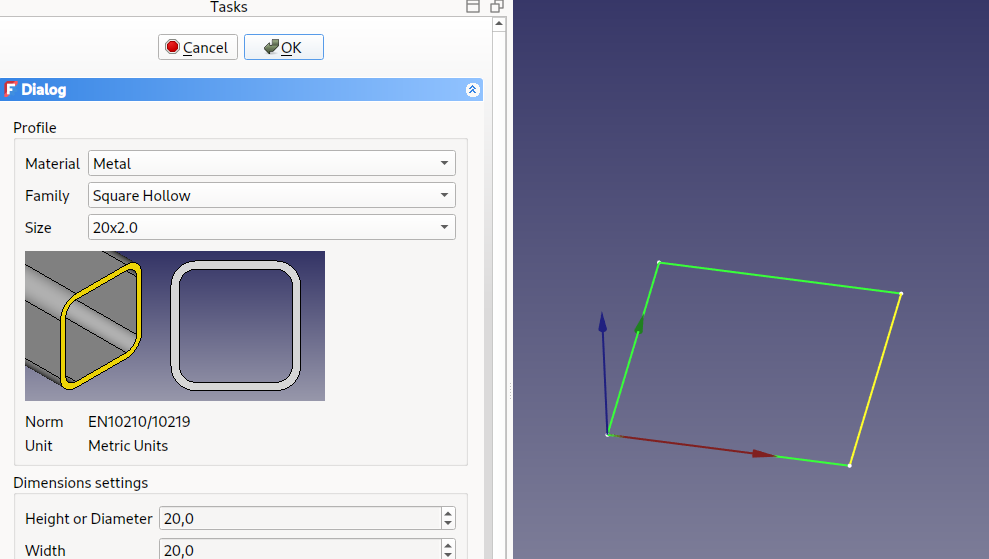
-
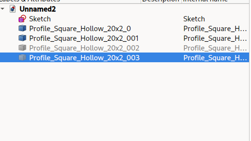
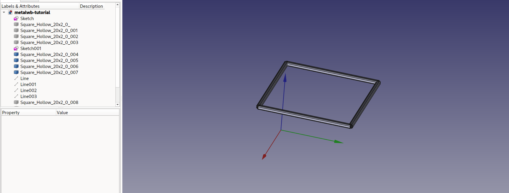
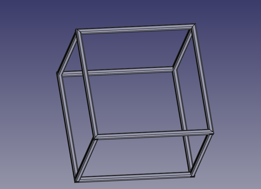
Press OK in the task panel. You now have four profiles and your first frame.
Going 3D
We can build more complex shapes, and there are several ways of doing it.
More sketches (part 1)
We can add more sketches to our project:
-
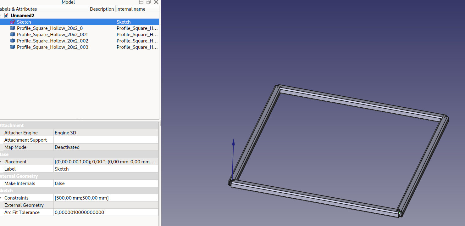
Create a new Sketch.
-
Select the same orientation as before (XY).
-
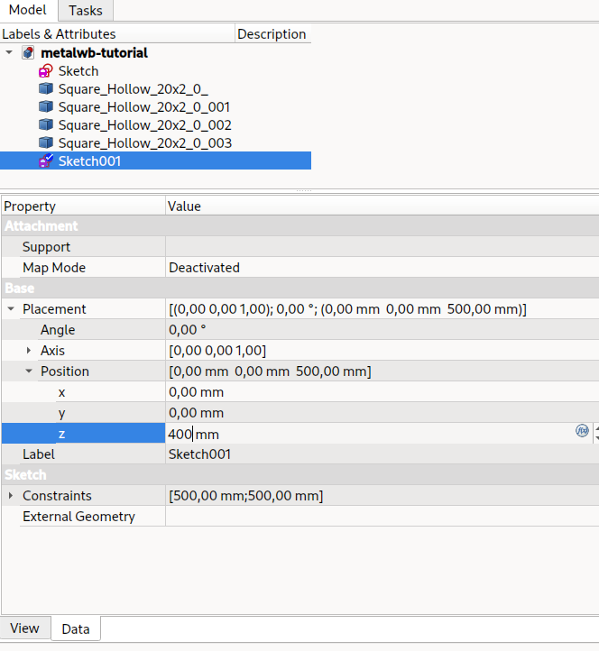
Draw a square with the same size and placement as before.
-
Change the position of the sketch to put it 400mm above the first one.
-
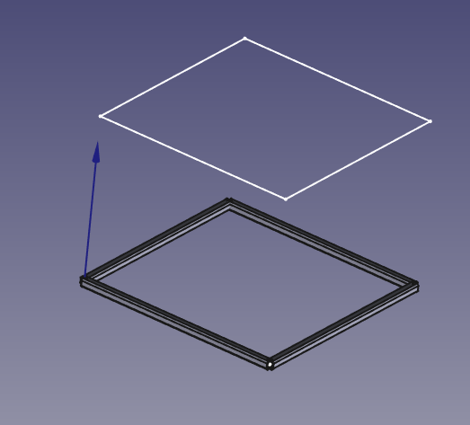
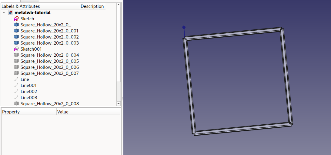
You can now use the Create Profile tool again to create another square frame.

Parametric Line
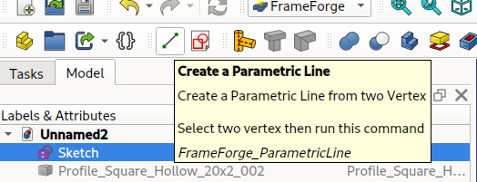
You can create Parametric Lines by joining two vertexes (points). Theses lines can be used for profiles as well.
-
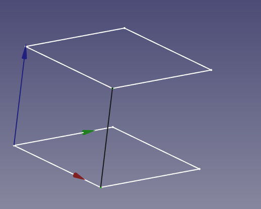
To see the sketches temporarily hide the profile objects with the Space Bar.
-
Select two vertexes.

-
Create a Parametric Line.
-
Repeat for the other 3 legs of the frame.
-
Use the Create Profile tool again to attach profiles to the 4 lines.
- Launch Create Profile.
- Select the profile you want.
- Select the 4 Parametric Lines.
- Press OK.
More sketches (part2)
There is another ways to add sketches, that allows to do more complicated stuff.
Sometimes you want to add a sketch at a specific location, and link it to another sketch. So that when you modify the first sketch, the second will follow. This is not possible with the Position / Base Placement, that is an absolute position, you have to "Map" the second sketch to the first sketch.
-
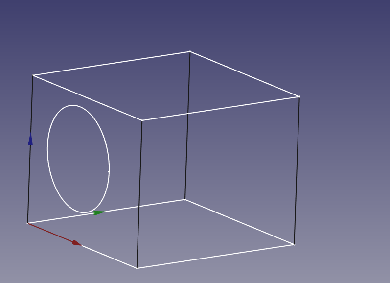
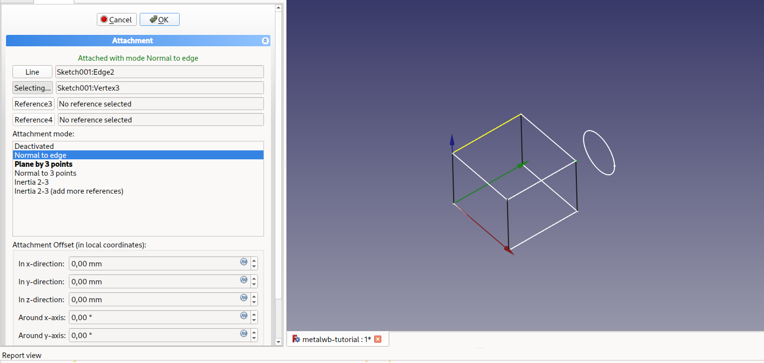
Create a new Sketch, and set its orientation to YZ.
Just for reference I have added a circle to the sketch so you can see where it is.
-
Click on the Map Mode property:
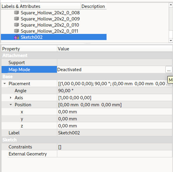
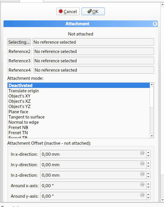
-
You can change the Map Mode, selecting faces, vertexes and edges. Here, our circle sketch has been realigned. There are a lot of options.
-
You can then edit the sketch, and create more lines and frames.
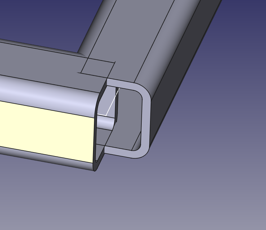
Bevels and corners
As you can see, the junctions are not good yet. The profiles are centered on the skeleton, and stop at the ends of the edges.
We are going to make corners and bevels. There are two methods for that.
Via Bevels property
This is the preferred option for simple frames.
-
Let's hide everything except the first frame we made.
-
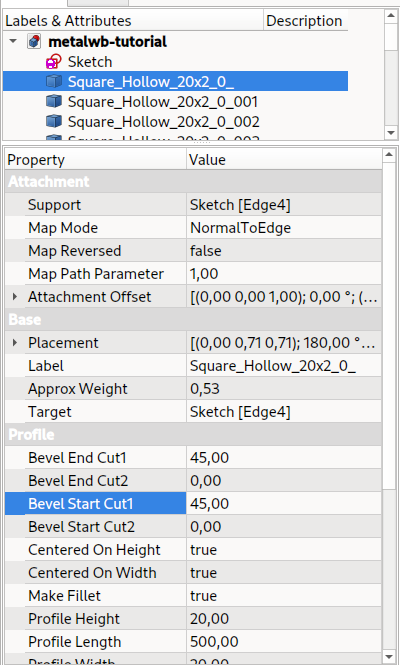
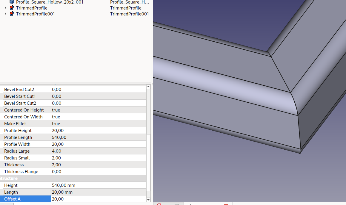
Select one of the profiles, and in the Property editor look for Bevel Start/End Cut1/Cut2.
-
There are 4 entries (Start/End Cut1/Cut2). These allow you to create bevels in the two axis, at the start or end of the profile. Negative angles work, and must be used to compensate directions.
-
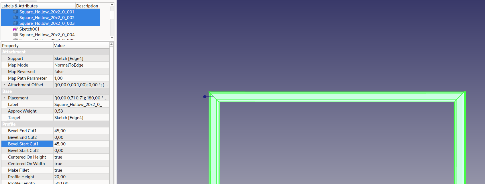
You can change the properties of multiple profiles at the same time.
Via Create Miter Ends tool
-
Let's show the other base frame.
-
First we must add offsets to the existing profiles. Offsets add to the dimensions of the edges. You can change the profiles one at a time, or change them all at once.
-
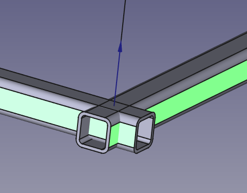
Deselect all objects, then select two touching Profiles. You must select faces in the 3D view, not objects in the Tree view.
-
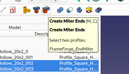
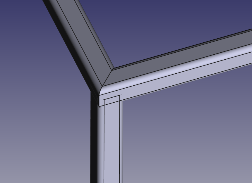
Click on the Create Miter Ends tool to create two trimmed profiles.
-
Repeat for the other corners of the second frame.
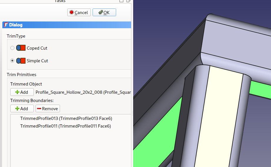
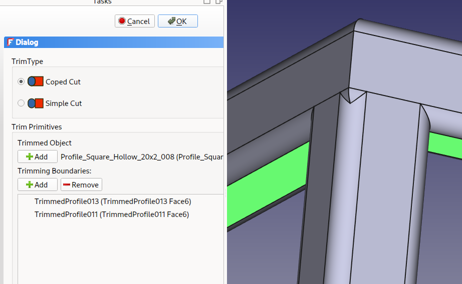
Via Trim Profile tool
-
When all profiles are made visible again, you can see that the vertical profiles are not cut as they should be.
-
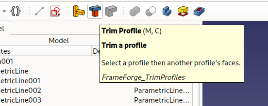
Launch the Trim Profile tool.
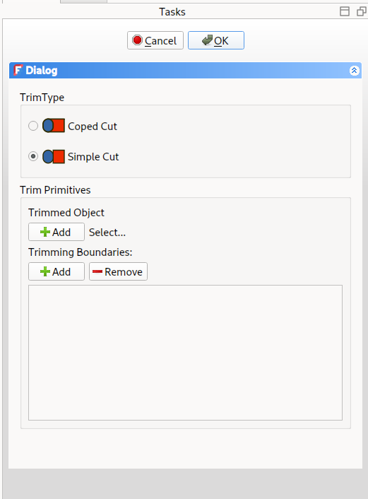
-
Select the vertical profile first, add it as the Trimmed Object with the
 button.
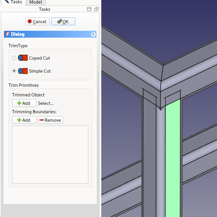
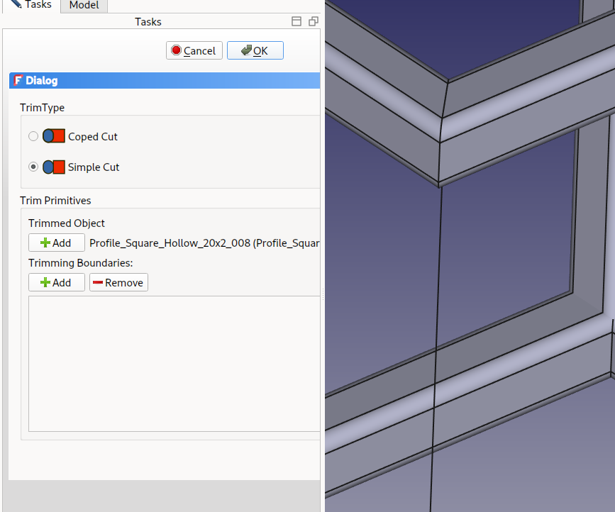
-
Select the Trimming Boundaries you want to cut with. Here I have rotated the view to select two bottom faces.
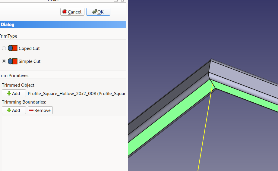

-
You can change the cut type: straight or following the other profile.
-
You also can add faces to trim the other side of the profile.
Organizing Objects
That's the bad part. I find the Tree view messy. Really messy.
Part Container
I often use Part containers to group profiles, sketches, etc.
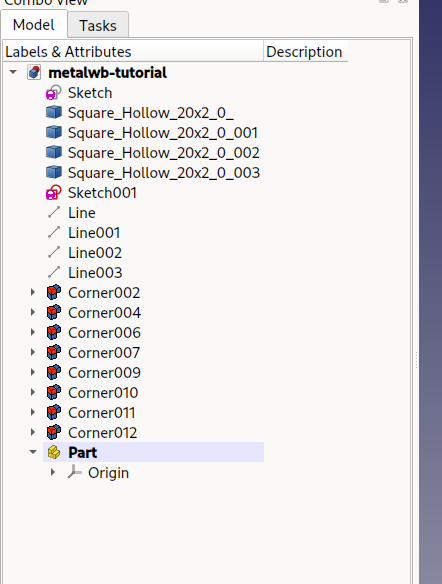
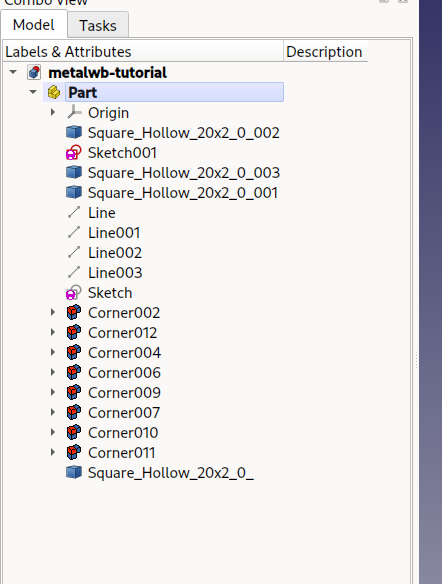
You should drag only one profile at a time into the container. I don't know why, but FreeCAD is not happy about a group drag. Sometime parts and profiles then jump out of the Part container.
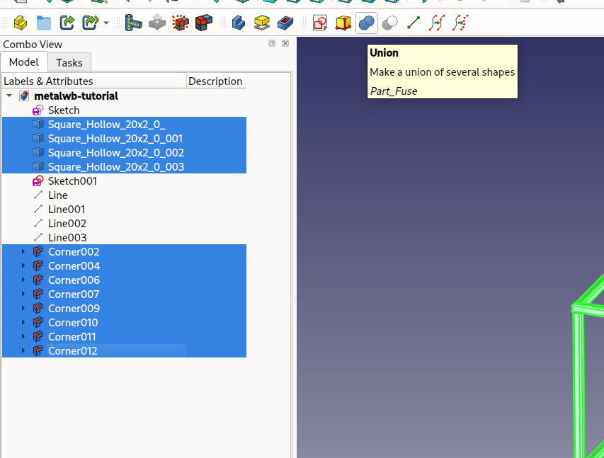
Fusion
You can fuse profiles together. It allows to group objects.
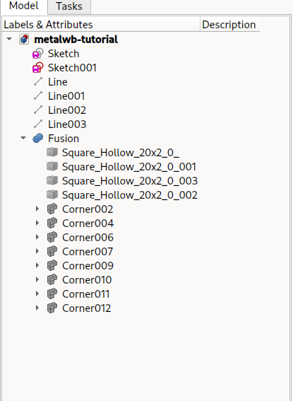
Using profiles in PartDesign
-
To use these profiles in PartDesign you need to create a fusion and then a Body.
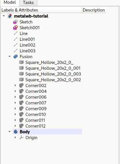
-
Drag and drop the fusion onto the Body.
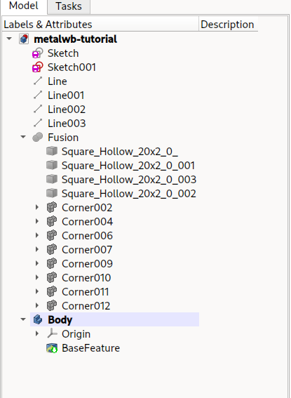
-
You now have a standard PartDesign Body and you can use PartDesign to do whatever you want. You can for example create holes.