Reinforcement DrawingDimensioning/pl
|
|
| Lokalizacja w menu |
|---|
| brak |
| Środowisko pracy |
| Zbrojenie |
| Domyślny skrót |
| brak |
| Wprowadzono w wersji |
| 0.19 |
| Zobacz także |
| brak |
Opis
Narzędzie Wymiarowanie rysunku zbrojenia umożliwia użytkownikowi tworzenie rysunków i wymiarowanie prętów zbrojeniowych.
To polecenie jest częścią zewnętrznego środowiska pracy Zbrojenie, które można zainstalować za pomocą Menadżera dodatków poprzez menu Przybory → Menadżera dodatków → Zbrojenie.
Rysunek i wymiarowanie prętów zbrojeniowych.
Użycie
1. Otwórz model FreeCAD zawierający pręty zbrojeniowe utworzone za pomocą środowiska pracy Zbrojenie.
2. Wybierz obiekt konstrukcji, a następnie wybierz
Wymiarowanie rysunku zbrojenia z narzędzi prętów zbrojeniowych.
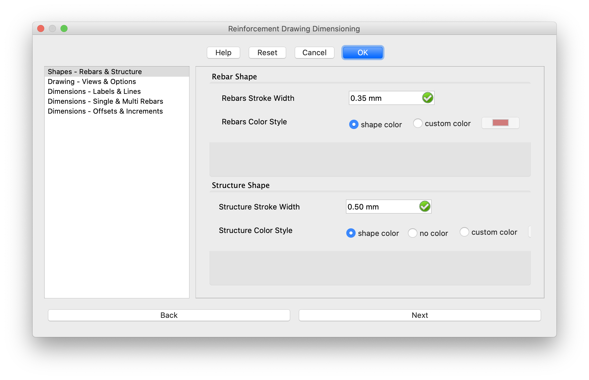
3. Na ekranie pojawi się okno dialogowe, jak pokazano poniżej.
4. Wprowadź wszystkie szczegóły związane z szerokością obrysu i kolorem prętów zbrojeniowych i konstrukcji.
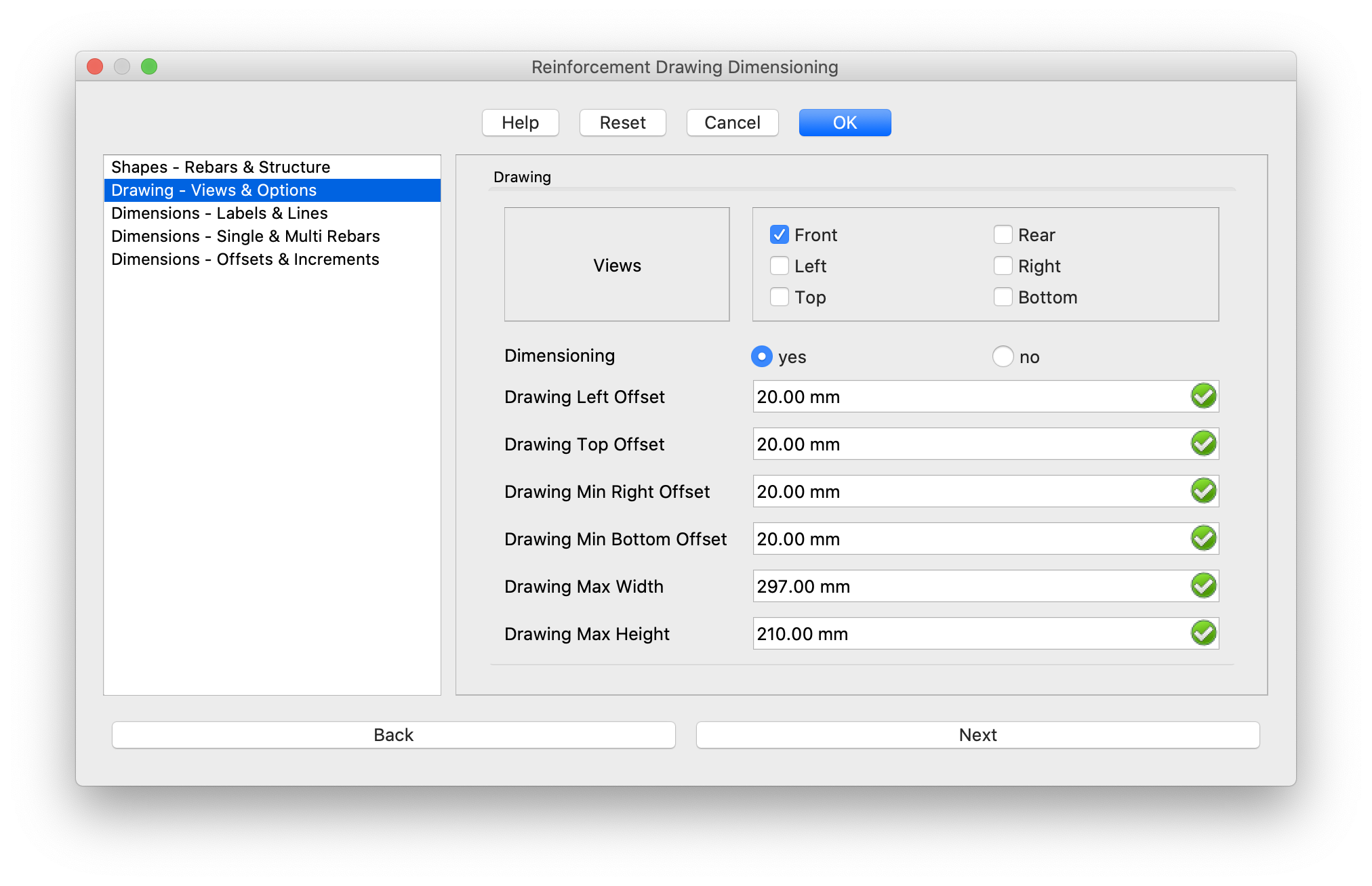
5. Kliknij przycisk Dalej, a okno dialogowe zostanie zaktualizowane w sposób pokazany poniżej.
6. Wprowadzanie opcji widoków rysunku, wymiarowania i szczegółów odsunięcia.
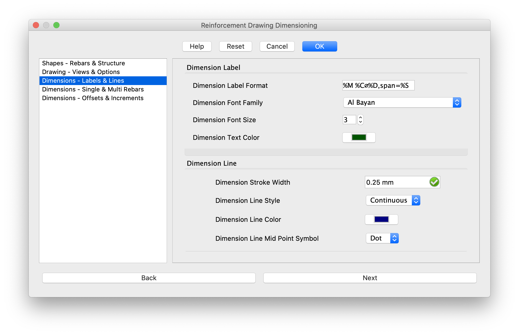
7. Kliknij Dalej, a okno dialogowe zostanie zaktualizowane w sposób pokazany poniżej.
8. Wprowadź etykietę wymiaru i szczegóły dotyczące linii.
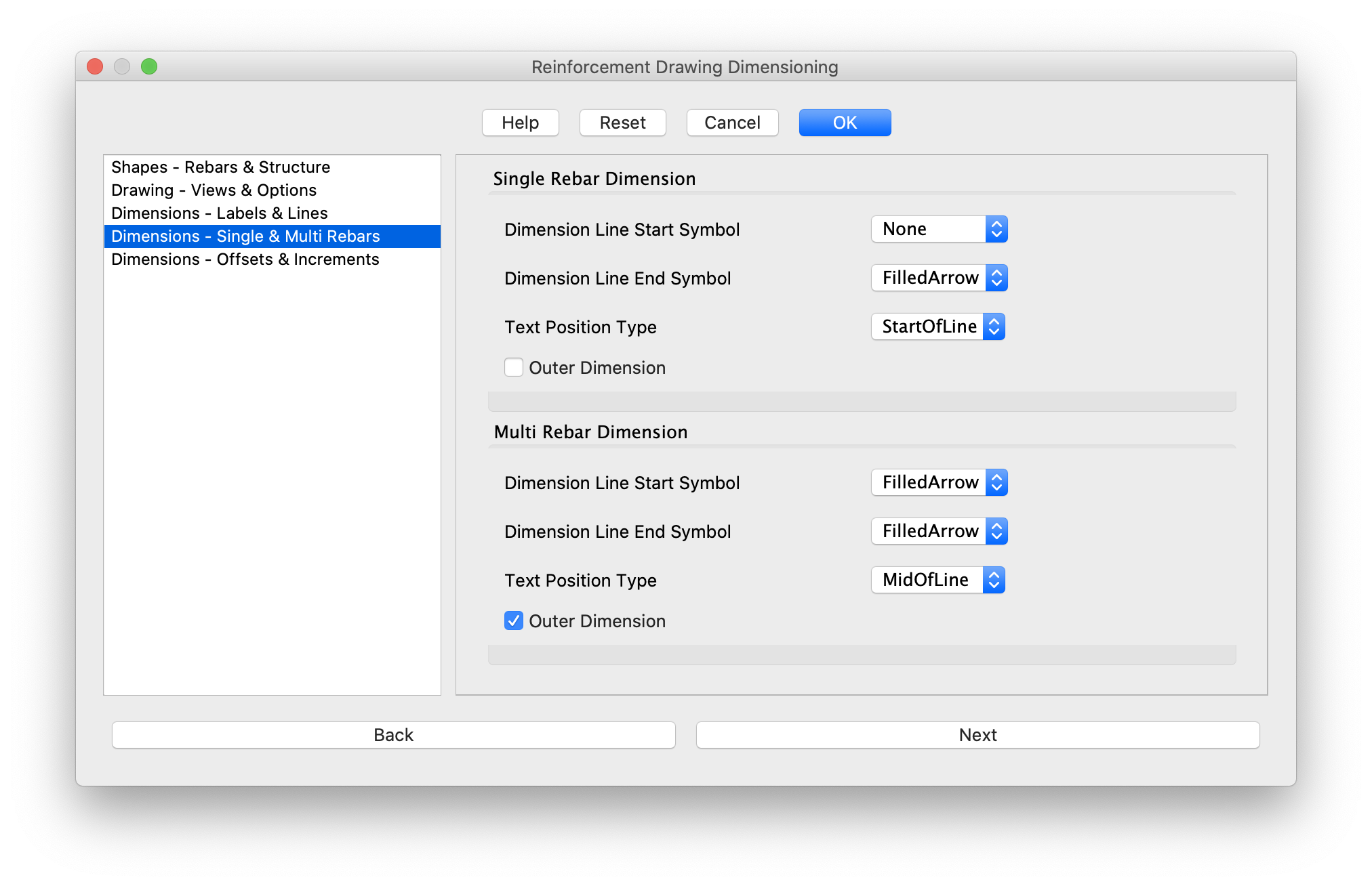
9. Kliknij przycisk Dalej, a okno dialogowe zostanie zaktualizowane w sposób pokazany poniżej.
10. Wprowadź szczegóły wymiarów pojedynczego pręta zbrojeniowego i wielu prętów zbrojeniowych.
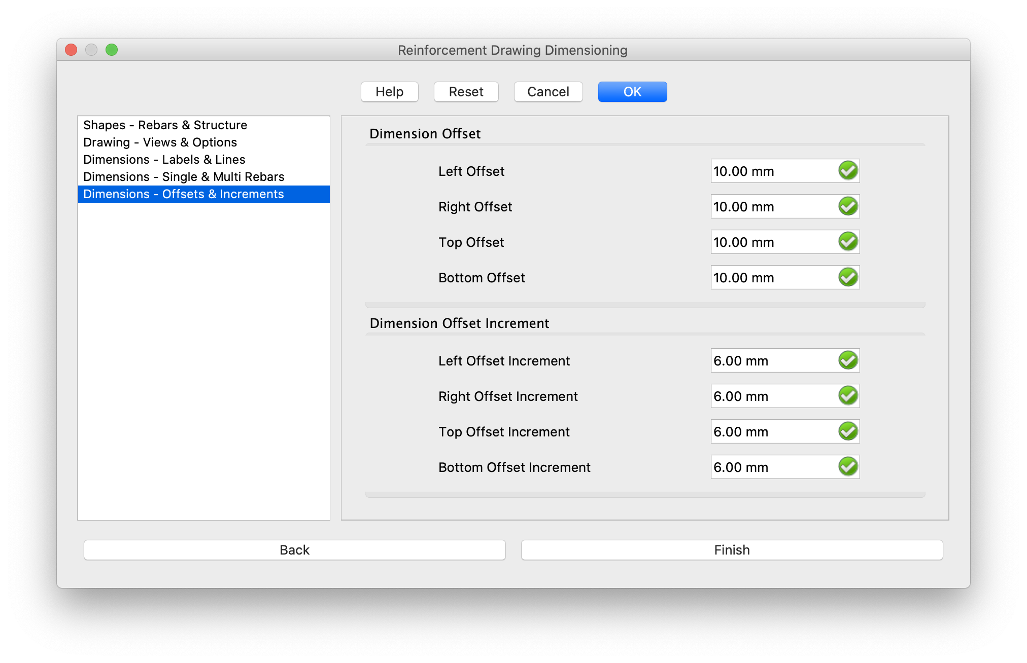
11. Kliknij Dalej, a okno dialogowe zostanie zaktualizowane w sposób pokazany poniżej.
12. Wprowadź szczegóły wymiarów i odsunięć linii wymiarowych.
13. Kliknij przycisk Zakończ, aby wygenerować rysunki.
Tworzenie skryptów
Zobacz również: Skrypty Architektury, Skrypty Zbrojenia oraz Podstawy tworzenia skryptów FreeCAD.
Narzędzie Wymiarowanie rysunku zbrojenia może być używane w makrodefinicjach i z konsoli Python za pomocą następującej funkcji:
Tworzenie rysunków i wymiarowanie zbrojenia
from ReinforcementDrawing import make_reinforcement_drawing

structure_drawing_page_dict = make_reinforcement_drawing.makeStructuresReinforcementDrawing(
    structure_list=None,
    rebars_list=None,
    view="Front",
    rebars_stroke_width=0.35,
    rebars_color_style="Automatic",
    rebars_color=(0.67, 0.0, 0.0),
    structure_stroke_width=0.5,
    structure_color_style="Automatic",
    structure_color=(0.3, 0.9, 0.91),
    drawing_left_offset=20,
    drawing_top_offset=20,
    drawing_min_right_offset=20,
    drawing_min_bottom_offset=20,
    drawing_max_width=0,   # It is set to 0 to automatically set the default width based on other parameters
    drawing_max_height=0,  # It is set to 0 to automatically set the default height based on other parameters
    template_file=str(Path(make_reinforcement_drawing.__file__).parent.absolute() / "Templates" / "A4_Landscape_blank.svg"),
    perform_dimensioning=True,
    dimension_rebars_filter_list=None,
    dimension_label_format="%M %C⌀%D,span=%S",
    dimension_font_family="DejaVu Sans",
    dimension_font_size=3,
    dimension_stroke_width=0.25,
    dimension_line_style="Continuous",
    dimension_line_color=(0.0, 0.0, 0.50),
    dimension_text_color=(0.0, 0.33, 0.0),
    dimension_single_rebar_line_start_symbol="None",
    dimension_single_rebar_line_end_symbol="FilledArrow",
    dimension_multi_rebar_line_start_symbol="FilledArrow",
    dimension_multi_rebar_line_end_symbol="FilledArrow",
    dimension_line_mid_point_symbol="Dot",
    dimension_left_offset=10,
    dimension_right_offset=10,
    dimension_top_offset=10,
    dimension_bottom_offset=10,
    dimension_left_offset_increment=6,
    dimension_right_offset_increment=6,
    dimension_top_offset_increment=6,
    dimension_bottom_offset_increment=6,
    dimension_single_rebar_outer_dim=False,
    dimension_multi_rebar_outer_dim=True,
    dimension_single_rebar_text_position_type="StartOfLine",
    dimension_multi_rebar_text_position_type="MidOfLine",
)
- Zwraca
structure_drawing_page_dict, słownik ze strukturą jako kluczem i odpowiednią stroną rysunku zbrojenia jako wartością. structure_listjest listą obiektów konstrukcyjnych do wygenerowania ich rysunku zbrojenia. Jeśli nie zostanie podana, konstrukcje zostaną wybrane z aktywnego dokumentu działającego jako obiekt główny dla prętów zbrojeniowych.rebars_listjest listą obiektów prętów zbrojeniowych, które mają zostać uwzględnione na rysunku. Jeśli nie zostanie podana, obiekty prętów zbrojeniowych posiadające obiekt główny na liście structure_list zostaną wybrane z aktywnego dokumentu.viewokreśla widok rysunku, który ma zostać wygenerowany. Może to być "Front", "Rear", "Left", "Right", "Top" lub "Bottom".rebars_stroke_widthokreśla szerokość obrysu prętów zbrojeniowych w rysunku SVG.rebars_color_styleokreśla styl kolorów prętów zbrojeniowych. Ustaw na "Automatic", aby automatycznie wybrać kolor prętów zbrojeniowych lub "Custom", aby wybrać wartość koloru kształtu ze zmiennejrebars_color.rebars_colorokreśla kolor wypełnienia prętów zbrojeniowych w rysunku SVG.
   Format: (r, g, b)
   Wartość r, g, b powinna wynosić od 0 do 1, więc może być konieczne podzielenie wartości r, g, b przez 255, aby uzyskać wartość od 0 do 1.
   Upewnij się, że wartości r, g, b muszą być zmiennoprzecinkowe.
   Przykład: (0.67, 0.0, 0.0)
structure_stroke_widthokreśla szerokość obrysu struktury w rysowaniu SVG.structure_color_styleokreśla styl wypełnienia konstrukcji. Ustaw na "Automatyczny", aby automatycznie wybrać kolor konstrukcji lub "Niestandardowy", aby wybrać wartość koloru konstrukcji ze zmiennejstructure_color.structure_colorokreśla kolor wypełnienia konstrukcji podczas rysowania SVG. Format: (r, g, b)drawing_left_offsetokreśla lewe odsunięcie widoku rysunku natemplate_file.drawing_top_offsetokreśla górne odsunięcie widoku rysunku natemplate_file.drawing_min_right_offsetokreśla minimalne odsunięcie widoku rysunku w prawo natemplate_file.drawing_min_bottom_offsetokreśla minimalne dolne odsunięcie widoku rysunku natemplate_file.drawing_max_widthokreśla maksymalną szerokość rysunku natemplate_file.drawing_max_heightokreśla maksymalną wysokość rysunku natemplate_file.template_fileto plik szablonu, który ma być używany dla strony rysunku zbrojenia.
perform_dimensioningokreśla, czy należy utworzyć wymiarowanie dla prętów zbrojeniowych na rysunku.dimension_rebars_filter_listto lista prętów zbrojeniowych do wymiarowania. Ustaw na Brak, aby zwymiarować wszystkie widoczne pręty zbrojeniowe na rysunku.dimension_label_formatto format używany dla etykiety wymiaru.
   Przykład: "%M %C⌀%D,span=%S"
   Gdzie: %M -> Rebar.Mark
          %C -> Rebar.Amount
          %D -> Rebar.Diameter
          %S -> Rebar span length
dimension_font_familyto rodzina czcionki etykiety wymiaru.dimension_font_sizeto rozmiar czcionki etykiety wymiaru.dimension_stroke_widthto szerokość obrysu linii wymiaru.dimension_line_styleto styl obrysu linii wymiarowej. Może to być "Continuous", "Dash", "Dot", "DashDot" lub "DashDotDot".dimension_line_colorto kolor linii wymiarowej.
   Format: (r, g, b)
   Wartość r, g, b powinna zawierać się w przedziale od 0 do 1, więc może być konieczne podzielenie wartości r, g, b przez 255, aby uzyskać wartość od 0 do 1.
   Upewnij się, że r, g, b muszą być zmiennoprzecinkowe
dimension_text_colorto kolor etykiety wymiaru.dimension_single_rebar_line_start_symbolto symbol początku linii wymiarowej, w przypadku gdy widoczny jest pojedynczy pręt zbrojeniowy. Może to być "FilledArrow", "Tick", "Dot" lub "None".dimension_single_rebar_line_end_symbolto symbol końca linii wymiarowej, w przypadku gdy widoczny jest pojedynczy pręt zbrojeniowy. Może to być "FilledArrow", "Tick", "Dot" lub "None".dimension_multi_rebar_line_start_symbolto symbol początku linii wymiarowej, w przypadku gdy widocznych jest wiele prętów zbrojeniowych. Może to być "FilledArrow", "Tick", "Dot" lub "None".dimension_multi_rebar_line_end_symbolto symbol końca linii wymiarowej, w przypadku gdy widocznych jest wiele prętów zbrojeniowych. Może to być "FilledArrow", "Tick", "Dot" lub "None".dimension_line_mid_point_symbolto symbol punktu środkowego linii wymiarowej. Może to być "Tick", "Dot" lub "None".dimension_left_offsetokreśla lewe odsunięcie wymiaru od rysunku.dimension_right_offsetokreśla prawe odsunięcie wymiaru od rysunku.dimension_top_offsetokreśla górne odsunięcie wymiaru od rysunku.dimension_bottom_offsetokreśla dolne odsunięcie wymiaru od rysunku.dimension_left_offset_incrementto przyrost lewego odsunięcia w celu odsunięcia każdej nowej etykiety wymiaru od rysunku.dimension_right_offset_incrementto przyrost prawego odsunięcia w celu odsunięcia każdej nowej etykiety wymiaru od rysunku.dimension_top_offset_incrementto przyrost górnego odsunięcia w celu odsunięcia każdej nowej etykiety wymiaru od rysunku.dimension_bottom_offset_incrementto przyrost dolnego odsunięcia w celu odsunięcia każdej nowej etykiety wymiaru od rysunku.
dimension_single_rebar_outer_dimokreśla, czy linie wymiarowe mają znajdować się poza rysunkiem zbrojenia, w przypadku gdy widoczny jest pojedynczy pręt zbrojeniowy.dimension_multi_rebar_outer_dimokreśla, czy linie wymiarowe mają znajdować się poza rysunkiem zbrojenia, w przypadku gdy widocznych jest wiele prętów zbrojeniowych.dimension_single_rebar_text_position_typeokreśla typ pozycji etykiety wymiaru, w przypadku gdy widoczny jest pojedynczy pręt zbrojeniowy. Może to być "StartOfLine", "MidOfLine" lub "EndOfLine".dimension_multi_rebar_text_position_typeokreśla typ pozycji etykiety wymiaru, w przypadku gdy widocznych jest wiele prętów zbrojeniowych. Może to być "StartOfLine", "MidOfLine" lub "EndOfLine".
Przykład
from pathlib import Path
import FreeCAD, Draft, Arch
from ColumnReinforcement import TwoTiesSixRebars
from ReinforcementDrawing import make_reinforcement_drawing

Rect = Draft.makeRectangle(400, 400)
Structure1 = Arch.makeStructure(Rect, height=1600)
Structure1.ViewObject.Transparency = 80
Structure2 = Arch.makeStructure(Rect, height=1600)
Structure2.ViewObject.Transparency = 80
Structure2.Placement = FreeCAD.Placement(FreeCAD.Vector(1000, 0, 0), FreeCAD.Rotation(FreeCAD.Vector(0, 0, 1), 0))
FreeCAD.ActiveDocument.recompute()

# Create Straight Rebars
TwoTiesSixRebars.makeTwoTiesSixRebars(
    l_cover_of_ties=40,
    r_cover_of_ties=40,
    t_cover_of_ties=40,
    b_cover_of_ties=40,
    offset_of_ties=100,
    bent_angle_of_ties=135,
    extension_factor_of_ties=2,
    dia_of_ties=8,
    number_spacing_check=True,
    number_spacing_value=10,
    dia_of_main_rebars=16,
    t_offset_of_rebars=40,
    b_offset_of_rebars=40,
    main_rebars_type="StraightRebar",
    hook_orientation="Top Inside",
    hook_extend_along="x-axis",
    l_rebar_rounding=None,
    hook_extension=None,
    ties_sequence=("Tie1", "Tie2"),
    structure=Structure1,
    facename="Face6",
)

# Create LShaped Rebars with hook along x-axis
TwoTiesSixRebars.makeTwoTiesSixRebars(
    l_cover_of_ties=40,
    r_cover_of_ties=40,
    t_cover_of_ties=40,
    b_cover_of_ties=40,
    offset_of_ties=100,
    bent_angle_of_ties=135,
    extension_factor_of_ties=2,
    dia_of_ties=8,
    number_spacing_check=True,
    number_spacing_value=10,
    dia_of_main_rebars=16,
    t_offset_of_rebars=-40,
    b_offset_of_rebars=-40,
    main_rebars_type="LShapeRebar",
    hook_orientation="Top Outside",
    hook_extend_along="x-axis",
    l_rebar_rounding=2,
    hook_extension=40,
    ties_sequence=("Tie1", "Tie2"),
    structure=Structure2,
    facename="Face6",
)

# Create Reinforcement Drawing and Dimensioning
for drawing_view in ("Front", "Rear", "Left", "Right", "Top", "Bottom"):
    struct_drawing_page_dict = make_reinforcement_drawing.makeStructuresReinforcementDrawing(
        structure_list=None,
        rebars_list=None,
        view="Front",
        rebars_stroke_width=0.35,
        rebars_color_style="Automatic",
        rebars_color=(0.67, 0.0, 0.0),
        structure_stroke_width=0.5,
        structure_color_style="Automatic",
        structure_color=(0.3, 0.9, 0.91),
        drawing_left_offset=20,
        drawing_top_offset=20,
        drawing_min_right_offset=20,
        drawing_min_bottom_offset=20,
        drawing_max_width=0,   # It is set to 0 to automatically set the default width based on other parameters
        drawing_max_height=0,  # It is set to 0 to automatically set the default height based on other parameters
        template_file=str(Path(make_reinforcement_drawing.__file__).parent.absolute() / "Templates" / "A4_Landscape_blank.svg"),
        perform_dimensioning=True,
        dimension_rebars_filter_list=None,
        dimension_label_format="%M %C⌀%D,span=%S",
        dimension_font_family="DejaVu Sans",
        dimension_font_size=3,
        dimension_stroke_width=0.25,
        dimension_line_style="Continuous",
        dimension_line_color=(0.0, 0.0, 0.50),
        dimension_text_color=(0.0, 0.33, 0.0),
        dimension_single_rebar_line_start_symbol="None",
        dimension_single_rebar_line_end_symbol="FilledArrow",
        dimension_multi_rebar_line_start_symbol="FilledArrow",
        dimension_multi_rebar_line_end_symbol="FilledArrow",
        dimension_line_mid_point_symbol="Dot",
        dimension_left_offset=10,
        dimension_right_offset=10,
        dimension_top_offset=10,
        dimension_bottom_offset=10,
        dimension_left_offset_increment=6,
        dimension_right_offset_increment=6,
        dimension_top_offset_increment=6,
        dimension_bottom_offset_increment=6,
        dimension_single_rebar_outer_dim=False,
        dimension_multi_rebar_outer_dim=True,
        dimension_single_rebar_text_position_type="StartOfLine",
        dimension_multi_rebar_text_position_type="MidOfLine",
    )
    for drawing_page in struct_drawing_page_dict.values():
        drawing_view = drawing_page.Views[0]
        drawing_view.setExpression(
            "LeftOffset",
            u".Template.Width.Value / 2 - .Width.Value * .Scale / 2",
        )
        drawing_view.setExpression(
            "TopOffset",
            u".Template.Height.Value / 2 - .Height.Value * .Scale / 2",
        )
        drawing_view.recompute(True)
        drawing_page.recompute(True)
Rysunek zbrojenia
Użycie
1. Otwórz model FreeCAD zawierający pręty zbrojeniowe utworzone za pomocą środowiska pracy Zbrojenie.
2. W konsoli FreeCAD Python skopiuj poniższy fragment kodu, aby wygenerować rysunek zbrojenia z różnych widoków dla każdego elementu konstrukcji.
from ReinforcementDrawing.make_reinforcement_drawing import (
    makeStructuresReinforcementDrawing,
)

for view in ("Front", "Rear", "Left", "Right", "Top", "Bottom"):
    makeStructuresReinforcementDrawing(view=view)
Obiekt ReinforcementDrawingView
Obiekt widoku SVG rysunku prętów zbrojeniowych.
Właściwości
- DANEStructure: Obiekt konstrukcji działający jako element główny dla prętów zbrojeniowych, które mają zostać uwzględnione na rysunku.
- DANERebars: Lista obiektów prętów zbrojeniowych, które mają zostać uwzględnione na rysunku.
- DANEView: Widok rysunku zbrojenia do wygenerowania. Może to być "Przód", "Tył", "Lewo", "Prawo", "Góra" lub "Dół".
- DANEPositionType: Typ położenia zbrojenia narysowanego na szablonie. Może przyjąć wartość "Automatycznie", aby obliczyć położenie rysunku przy użyciu DANELeftOffset, DANETopOffset, DANEMinRightOffset i DANEMinBottomOffset. LUB "Niestandardowy ", aby ustawić rozmieszczenie za pomocą DANEX i DANEY.
- DANERebarsStrokeWidth: Szerokość obrysu prętów zbrojeniowych w rysunku zbrojenia SVG.
- DANERebarsColorStyle: Styl koloru prętów zbrojeniowych w rysunku zbrojenia SVG. Ustaw na "Automatycznie ", aby automatycznie wybrać kolor prętów zbrojeniowych LUB "Niestandardowy ", aby wybrać wartość koloru kształtu z DANERebarsColor.
- DANERebarsColor: Kolor prętów zbrojeniowych w rysunku zbrojenia SVG.
- DANEStructureStrokeWidth: Szerokość obrysu konstrukcji w rysunku zbrojenia SVG.
- DANEStructureColorStyle: Styl koloru konstrukcji w rysunku zbrojenia SVG. Ustaw na "Automatycznie", aby automatycznie wybrać kolor prętów zbrojeniowych, "Niestandardowy", aby wybrać wartość koloru kształtu z DANEStructureColor. LUB "Brak", aby nie wypełniać struktury.
- DANEStructureColor: Kolor konstrukcji w rysunku zbrojenia SVG.
- DANETemplate: Szablon dla widoku rysunku zbrojenia.
- DANEWidth: Szerokość widoku rysunku zbrojenia SVG.
- DANEHeight: Wysokość widoku SVG rysunku zbrojenia.
- DANELeftOffset: Lewe odsunięcie widoku rysunku zbrojenia na szablonie.
- DANETopOffset: Górne odsunięcie widoku rysunku zbrojenia na szablonie.
- DANEMinRightOffset: Minimalne prawe odsunięcie widoku rysunku zbrojenia na szablonie.
- DANEMinBottomOffset: Minimalne dolne odsunięcie widoku rysunku zbrojenia w szablonie.
- DANEMaxWidth: Maksymalna szerokość widoku rysunku zbrojenia.
- DANEMaxHeight: Maksymalna wysokość widoku rysunku zbrojenia.
- DANEVisibleRebars: Lista widocznych obiektów prętów zbrojeniowych w widoku rysunku.
- DANEDimensionLeftOffset: Lewe odsunięcie dla każdego nowego obiektu ReinforcementDimensioning.
- DANEDimensionRightOffset: Prawe odsunięcie dla każdego nowego obiektu ReinforcementDimensioning.
- DANEDimensionTopOffset: Górne odsunięcie dla każdego nowego obiektu ReinforcementDimensioning.
- DANEDimensionBottomOffset: dolne odsunięcie dla każdego nowego obiektu ReinforcementDimensioning.
Tworzenie skryptów
Zobacz również: Skrypty Architektury, Skrypty Zbrojenia oraz Podstawy tworzenia skryptów FreeCAD.
Narzędzie Wymiarowanie rysunku zbrojenia może być używane w makrodefinicjach i z konsoli Python za pomocą następującej funkcji:
Tworzenie rysunku zbrojenia
Dla jednej konstrukcji
from ReinforcementDrawing.make_reinforcement_drawing import (
    makeReinforcementDrawing,
)

reinforcement_drawing_page = makeReinforcementDrawing(
    structure,
    rebars_list,
    view,
    rebars_stroke_width,
    rebars_color_style,
    rebars_color,
    structure_stroke_width,
    structure_color_style,
    structure_color,
    drawing_left_offset,
    drawing_top_offset,
    drawing_min_right_offset,
    drawing_min_bottom_offset,
    drawing_max_width,
    drawing_max_height,
    template_file,
    dimension_left_offset,
    dimension_right_offset,
    dimension_top_offset,
    dimension_bottom_offset,
)
- Tworzy obiekt
ReinforcementDrawingViewdla podanej listy obiektów konstrukcji i prętów. - Zwraca
Reinforcement_drawing_pagetypuTechDraw::DrawPage. viewokreśla widok rysunku, który ma zostać wygenerowany. Może przyjmować wartości "Przód", "Tył", "Lewo", "Prawo", "Góra" lub "Dół".rebars_stroke_widthokreśla szerokość obrysu prętów zbrojeniowych w rysunku SVG.rebars_color_styleokreśla styl kolorów prętów zbrojeniowych. Ustaw na "Automatycznie", aby automatycznie wybrać kolor prętów zbrojeniowych lub "Niestandardowy", aby wybrać wartość koloru kształtu ze zmiennejrebars_color.rebars_colorokreśla kolor wypełnienia prętów zbrojeniowych w rysunku SVG.
   Format: (r, g, b)
   Wartość r, g, b powinna wynosić od 0 do 1, więc może być konieczne podzielenie wartości r, g, b przez 255, aby uzyskać wartość od 0 do 1.
   Upewnij się, że wartości r, g, b muszą być zmiennoprzecinkowe.
   Przykład: (0.67, 0.0, 0.0)
structure_stroke_widthokreśla szerokość obrysu konstrukcji w rysunku SVG.structure_color_styleokreśla styl wypełnienia konstrukcji. Ustaw na "Automatycznie", aby automatycznie wybrać kolor konstrukcji lub "Niestandardowy", aby wybrać wartość koloru konstrukcji ze zmiennejstructure_color.structure_colorokreśla kolor wypełnienia konstrukcji w rysunku SVG. Format: (r, g, b)drawing_left_offsetokreśla lewe odsunięcie widoku rysunku natemplate_file.drawing_top_offsetokreśla górne odsunięcie widoku rysunku natemplate_file.drawing_min_right_offsetokreśla minimalne prawe odsunięcie widoku rysunku natemplate_file.drawing_min_bottom_offsetokreśla minimalne dolne odsunięcie widoku rysunku natemplate_file.drawing_max_widthokreśla maksymalną szerokość rysunku natemplate_file.drawing_max_heightokreśla maksymalną wysokość rysunku natemplate_file.template_filejest plikiem szablonu, który ma być użyty dla strony rysunku zbrojenia.dimension_left_offsetokreśla lewe odsunięcie wymiaru od rysunku.dimension_right_offsetokreśla prawe odsunięcie wymiaru od rysunku.dimension_top_offsetokreśla górne odsunięcie wymiaru od rysunku.dimension_bottom_offsetokreśla dolne odsunięcie wymiaru od rysunku.
Przykład
from pathlib import Path
import FreeCAD, Draft, Arch
from ColumnReinforcement import TwoTiesSixRebars
from ReinforcementDrawing import make_reinforcement_drawing

Rect = Draft.makeRectangle(400, 400)
Structure = Arch.makeStructure(Rect, height=1600)
Structure.ViewObject.Transparency = 80
FreeCAD.ActiveDocument.recompute()

# Tworzenie prostych prętów zbrojeniowych.
RebarGroup = TwoTiesSixRebars.makeTwoTiesSixRebars(
    l_cover_of_ties=40,
    r_cover_of_ties=40,
    t_cover_of_ties=40,
    b_cover_of_ties=40,
    offset_of_ties=100,
    bent_angle_of_ties=135,
    extension_factor_of_ties=2,
    dia_of_ties=8,
    number_spacing_check=True,
    number_spacing_value=10,
    dia_of_main_rebars=16,
    t_offset_of_rebars=40,
    b_offset_of_rebars=40,
    main_rebars_type="StraightRebar",
    hook_orientation="Top Inside",
    hook_extend_along="x-axis",
    l_rebar_rounding=None,
    hook_extension=None,
    ties_sequence=("Tie1", "Tie2"),
    structure=Structure,
    facename="Face6",
)

rebars = Draft.get_objects_of_type(FreeCAD.ActiveDocument.Objects, "Rebar")

# Utwórz rysunek zbrojenia.
for drawing_view in ("Front", "Rear", "Left", "Right", "Top", "Bottom"):
    make_reinforcement_drawing.makeReinforcementDrawing(
        structure=Structure,
        rebars_list=rebars,
        view=drawing_view,
        rebars_stroke_width=0.35,
        rebars_color_style="Automatic",
        rebars_color=(0.67, 0.0, 0.0),
        structure_stroke_width=0.5,
        structure_color_style="Automatic",
        structure_color=(0.3, 0.9, 0.91),
        drawing_left_offset=20,
        drawing_top_offset=20,
        drawing_min_right_offset=20,
        drawing_min_bottom_offset=20,
        drawing_max_width=0,   # It is set to 0 to automatically set the default width based on other parameters
        drawing_max_height=0,  # It is set to 0 to automatically set the default height based on other parameters
        template_file=str(Path(make_reinforcement_drawing.__file__).parent.absolute() / "Templates" / "A4_Landscape_blank.svg"),
        dimension_left_offset=10,
        dimension_right_offset=10,
        dimension_top_offset=10,
        dimension_bottom_offset=10,
    )
Dla wielu konstrukcji
from ReinforcementDrawing.make_reinforcement_drawing import (
    makeStructuresReinforcementDrawing,
)

structure_drawing_page_dict = makeStructuresReinforcementDrawing(
    structure_list=None,
    rebars_list=None,
    view="Front",
    rebars_stroke_width=REBARS_STROKE_WIDTH,
    rebars_color_style=REBARS_COLOR_STYLE,
    rebars_color=REBARS_COLOR,
    structure_stroke_width=STRUCTURE_STROKE_WIDTH,
    structure_color_style=STRUCTURE_COLOR_STYLE,
    structure_color=STRUCTURE_COLOR,
    drawing_left_offset=DRAWING_LEFT_OFFSET,
    drawing_top_offset=DRAWING_TOP_OFFSET,
    drawing_min_right_offset=DRAWING_MIN_RIGHT_OFFSET,
    drawing_min_bottom_offset=DRAWING_MIN_BOTTOM_OFFSET,
    drawing_max_width=DRAWING_MAX_WIDTH,
    drawing_max_height=DRAWING_MAX_HEIGHT,
    template_file=TEMPLATE_FILE,
)
- Zwraca
structure_drawing_page_dict, słownik z konstrukcją jako kluczem i odpowiednią stroną rysunku zbrojenia jako wartością. structure_listjest listą obiektów konstrukcyjnych do wygenerowania ich rysunku zbrojenia. Jeśli nie zostanie podana, konstrukcje zostaną wybrane z aktywnego dokumentu działającego jako host dla obiektów prętów zbrojeniowych.rebars_listjest listą obiektów prętów zbrojeniowych, które mają zostać uwzględnione na rysunku. Jeśli nie zostanie podana, obiekty prętów zbrojeniowych posiadające obiekt główny na liście structure_list zostaną wybrane z aktywnego dokumentu.
Przykład
from pathlib import Path
import FreeCAD, Draft, Arch
from ColumnReinforcement import TwoTiesSixRebars
from ReinforcementDrawing import make_reinforcement_drawing

Rect = Draft.makeRectangle(400, 400)
Structure1 = Arch.makeStructure(Rect, height=1600)
Structure1.ViewObject.Transparency = 80
Structure2 = Arch.makeStructure(Rect, height=1600)
Structure2.ViewObject.Transparency = 80
Structure2.Placement = FreeCAD.Placement(FreeCAD.Vector(1000, 0, 0), FreeCAD.Rotation(FreeCAD.Vector(0, 0, 1), 0))
FreeCAD.ActiveDocument.recompute()

# Tworzenie prostych prętów zbrojeniowych.
TwoTiesSixRebars.makeTwoTiesSixRebars(
    l_cover_of_ties=40,
    r_cover_of_ties=40,
    t_cover_of_ties=40,
    b_cover_of_ties=40,
    offset_of_ties=100,
    bent_angle_of_ties=135,
    extension_factor_of_ties=2,
    dia_of_ties=8,
    number_spacing_check=True,
    number_spacing_value=10,
    dia_of_main_rebars=16,
    t_offset_of_rebars=40,
    b_offset_of_rebars=40,
    main_rebars_type="StraightRebar",
    hook_orientation="Top Inside",
    hook_extend_along="x-axis",
    l_rebar_rounding=None,
    hook_extension=None,
    ties_sequence=("Tie1", "Tie2"),
    structure=Structure1,
    facename="Face6",
)

# Utwórz pręty zbrojeniowe w kształcie litery L z hakiem wzdłuż osi X.
TwoTiesSixRebars.makeTwoTiesSixRebars(
    l_cover_of_ties=40,
    r_cover_of_ties=40,
    t_cover_of_ties=40,
    b_cover_of_ties=40,
    offset_of_ties=100,
    bent_angle_of_ties=135,
    extension_factor_of_ties=2,
    dia_of_ties=8,
    number_spacing_check=True,
    number_spacing_value=10,
    dia_of_main_rebars=16,
    t_offset_of_rebars=-40,
    b_offset_of_rebars=-40,
    main_rebars_type="LShapeRebar",
    hook_orientation="Top Outside",
    hook_extend_along="x-axis",
    l_rebar_rounding=2,
    hook_extension=40,
    ties_sequence=("Tie1", "Tie2"),
    structure=Structure2,
    facename="Face6",
)

# Utwórz rysunek zbrojenia.
for drawing_view in ("Front", "Rear", "Left", "Right", "Top", "Bottom"):
    make_reinforcement_drawing.makeStructuresReinforcementDrawing(
        structure_list=None,
        rebars_list=None,
        view=drawing_view,
        rebars_stroke_width=0.35,
        rebars_color_style="Automatic",
        rebars_color=(0.67, 0.0, 0.0),
        structure_stroke_width=0.5,
        structure_color_style="Automatic",
        structure_color=(0.3, 0.9, 0.91),
        drawing_left_offset=20,
        drawing_top_offset=20,
        drawing_min_right_offset=20,
        drawing_min_bottom_offset=20,
        drawing_max_width=0,   # It is set to 0 to automatically set the default width based on other parameters
        drawing_max_height=0,  # It is set to 0 to automatically set the default height based on other parameters
        template_file=str(Path(make_reinforcement_drawing.__file__).parent.absolute() / "Templates" / "A4_Landscape_blank.svg"),
        dimension_left_offset=10,
        dimension_right_offset=10,
        dimension_top_offset=10,
        dimension_bottom_offset=10,
    )
Wymiarowanie zbrojenia
Użycie
1. Otwórz model FreeCAD zawierający pręty zbrojeniowe utworzone za pomocą środowiska pracy Zbrojenie.
2. W konsoli FreeCAD Python skopiuj poniższy fragment kodu, aby wygenerować rysunek zbrojenia z wymiarowaniem z różnych widoków dla każdego elementu konstrukcji.
from ReinforcementDrawing.make_reinforcement_drawing import (
    makeStructuresReinforcementDrawing,
)

for view in ("Front", "Rear", "Left", "Right", "Top", "Bottom"):
    struct_drawing_page_dict = makeStructuresReinforcementDrawing(
        view=view, perform_dimensioning=True
    )
    for drawing_page in struct_drawing_page_dict.values():
        drawing_view = drawing_page.Views[0]
        drawing_view.setExpression(
            "LeftOffset",
            u".Template.Width.Value / 2 - .Width.Value * .Scale / 2",
        )
        drawing_view.setExpression(
            "TopOffset",
            u".Template.Height.Value / 2 - .Height.Value * .Scale / 2",
        )
        drawing_view.recompute(True)
        drawing_page.recompute(True)
Obiekt ReinforcementDimensioning
Obiekt widoku SVG wymiarowania prętów zbrojeniowych.
Właściwości
- DANEParentDrawingView: Nadrzędny obiekt ReinforcementDrawingView zawierający rysunek obiektu Pręta.
- DANERebar: Obiekt Pręta zbrojeniowego do wykonania wymiarowania.
- DANEWayPointsType: Typ WayPoints linii wymiarowej. Może to być "Automatycznie" (aby automatycznie wykonać wymiarowanie obiektu Rebar) lub " Niestandardowo ", aby użyć DANEWayPoints do wykonania wymiarowania.
- DANEWayPoints: Lista punktów wektorowych, które zostaną użyte do wygenerowania linii wymiarowej.
- DANETextPositionType: Typ pozycji tekstu wymiaru. Może przyjmować wartość "StartOfLine", "MidOfLine" lub "EndOfLine".
- DANEDimensionFormat: Format etykiety wymiaru.
   Przykład: "%M %C⌀%D,span=%S".
   Tutaj: %M -> Rebar.Mark
          %C -> Rebar.Amount
          %D -> Rebar.Diameter
          %S -> Rebar span length
- DANEFont: Rodzina czcionek etykiety wymiaru.
- DANEFontSize: Rozmiar czcionki etykiety wymiaru.
- DANEStrokeWidth: Szerokość obrysu linii wymiaru.
- DANELineStyle: Styl obrysu linii wymiarowej. Może przyjmować wartość " Ciągła", "Kreska", "Kropka", "KreskaKropka" lub "KreskaKropkaKropka".
- DANELineColor: Kolor linii wymiarowej.
- DANETextColor: Kolor etykiety wymiaru.
- DANELineStartSymbol: Symbol początkowy linii wymiaru. Może przyjmować wartość "FilledArrow", "Tick", "Dot" lub "None".
- DANELineEndSymbol: Symbol końca linii wymiarowej. Może przyjmować wartość "FilledArrow", "Tick", "Dot" lub "None".
- DANELineMidPointSymbol: Symbol punktu środkowego linii wymiarowej. Może przyjmować wartość "Tick", "Dot" lub "None".
- DANEDimensionLeftOffset: Lewe odsunięcie dla automatycznego wymiarowania zbrojenia.
- DANEDimensionRightOffset: Prawe odsunięcie dla automatycznego wymiarowania zbrojenia.
- DANEDimensionTopOffset: Górne odsunięcie dla automatycznego wymiarowania zbrojenia.
- DANEDimensionBottomOffset: Dolne odsunięcie dla automatycznego wymiarowania zbrojenia.
- DANESingleRebar_LineStartSymbol: Symbol początku linii wymiarowej, w przypadku gdy widoczny jest pojedynczy pręt zbrojeniowy. Może przyjmować wartość "FilledArrow", "Tick", "Dot" lub "None". Jest używany tylko wtedy, gdy DANEWayPointsType jest ustawiony na "Automatic".
- DANESingleRebar_LineEndSymbol: Symbol końca linii wymiarowej, w przypadku gdy widoczny jest pojedynczy pręt zbrojeniowy. Może to być "FilledArrow", "Tick", "Dot" lub "None". Jest używany tylko wtedy, gdy DANEWayPointsType jest ustawiony na "Automatic".
- DANEMultiRebar_LineStartSymbol: Symbol początku linii wymiarowej, w przypadku gdy widocznych jest wiele prętów zbrojeniowych. Może to być "FilledArrow", "Tick", "Dot" lub "None". Jest używany tylko wtedy, gdy DANEWayPointsType jest ustawiony na "Automatycznie".
- DANESingleRebar_OuterDimension: Określa, czy linie wymiarowe mają znajdować się poza rysunkiem zbrojenia, w przypadku gdy widoczny jest pojedynczy pręt zbrojeniowy. Jest używany tylko wtedy, gdy DANEWayPointsType jest ustawiony na "Automatycznie".
- DANEMultiRebar_OuterDimension: Określa, czy linie wymiarowe mają znajdować się poza rysunkiem zbrojenia, w przypadku gdy widocznych jest wiele prętów zbrojeniowych. Jest używany tylko wtedy, gdy DANEWayPointsType jest ustawiony na "Automatycznie".
- DANESingleRebar_TextPositionType: Określa typ położenia etykiety wymiaru, w przypadku gdy widoczny jest pojedynczy pręt zbrojeniowy. Może przyjmować wartości "StartOfLine", "MidOfLine" lub "EndOfLine". Jest używany tylko wtedy, gdy DANEWayPointsType jest ustawiony na "Automatycznie".
- DANEMultiRebar_TextPositionType: Określa typ położenia etykiety wymiaru w przypadku, gdy widocznych jest wiele prętów zbrojeniowych. Może przyjmować wartości "StartOfLine", "MidOfLine" lub "EndOfLine". Jest używany tylko wtedy, gdy DANEWayPointsType jest ustawiony na "Automatycznie".
Tworzenie skryptów
Zobacz również: Skrypty Architektury, Skrypty Zbrojenia oraz Podstawy tworzenia skryptów FreeCAD.
Narzędzie Wymiarowanie rysunku zbrojenia może być używane w makrodefinicjach i z konsoli Python za pomocą następującej funkcji:
Tworzenie obiektu wymiarowania zbrojenia
from ReinforcementDrawing.ReinforcementDimensioning import (
    makeReinforcementDimensioningObject,
)

dimension_object = makeReinforcementDimensioningObject(
    rebar,
    parent_drawing_view,
    drawing_page=None,
    dimension_label_format="%M %C⌀%D,span=%S",
    dimension_font_family="DejaVu Sans",
    dimension_font_size=3,
    dimension_stroke_width=0.25,
    dimension_line_style="Continuous",
    dimension_line_color=(0.0, 0.0, 0.50),
    dimension_text_color=(0.0, 0.33, 0.0),
    dimension_single_rebar_line_start_symbol="None",
    dimension_single_rebar_line_end_symbol="FilledArrow",
    dimension_multi_rebar_line_start_symbol="FilledArrow",
    dimension_multi_rebar_line_end_symbol="FilledArrow",
    dimension_line_mid_point_symbol="Dot",
    dimension_left_offset_increment=10,
    dimension_right_offset_increment=10,
    dimension_top_offset_increment=10,
    dimension_bottom_offset_increment=10,
    dimension_single_rebar_outer_dim=False,
    dimension_multi_rebar_outer_dim=True,
    dimension_single_rebar_text_position_type="StartOfLine",
    dimension_multi_rebar_text_position_type="MidOfLine",
)
- Tworzy i zwraca obiekt
ReinforcementDimensioningdla danego obiekturebar. parent_drawing_viewjest obiektemReinforcementDrawingViewzawierającym rysunek obiekturebar.drawing_pagejest obiektem typu TechDraw::DrawPage używanym do wyświetlaniaparent_drawing_view.dimension_label_formatjest formatem używanym dla etykiety wymiaru.
   Przykład: "%M %C⌀%D,span=%S".
   Tutaj: %M -> Rebar.Mark
          %C -> Rebar.Amount
          %D -> Rebar.Diameter
          %S -> Rebar span length
dimension_font_familyto rodzina czcionki etykiety wymiaru.dimension_font_sizeto rozmiar czcionki etykiety wymiaru.dimension_stroke_widthto szerokość obrysu linii wymiaru.dimension_line_styleto styl obrysu linii wymiarowej. Może przyjmować wartość "Ciągła", "Kreska", "Kropka", "KreskaKropka" lub "KreskaKropkaKropka".dimension_line_colorto kolor linii wymiarowej.
   Format: (r, g, b)
   Wartość r, g, b powinna zawierać się w przedziale od 0 do 1, więc może być konieczne podzielenie wartości r, g, b przez 255, aby uzyskać wartość od 0 do 1.
   Upewnij się, że r, g, b muszą być zmiennoprzecinkowe
dimension_text_colorto kolor etykiety wymiaru.dimension_single_rebar_line_start_symbolto symbol początku linii wymiarowej, w przypadku gdy widoczny jest pojedynczy pręt zbrojeniowy. Może przyjmować wartość "FilledArrow", "Tick", "Dot" lub "None".dimension_single_rebar_line_end_symbolto symbol końca linii wymiarowej, w przypadku gdy widoczny jest pojedynczy pręt zbrojeniowy. Może przyjmować wartość "FilledArrow", "Tick", "Dot" lub "None".dimension_multi_rebar_line_start_symbolto symbol początku linii wymiarowej, w przypadku gdy widocznych jest wiele prętów zbrojeniowych. Może przyjmować wartość "FilledArrow", "Tick", "Dot" lub "None".dimension_multi_rebar_line_end_symbolto symbol końca linii wymiarowej, w przypadku gdy widocznych jest wiele prętów zbrojeniowych. Może to być "FilledArrow", "Tick", "Dot" lub "None".dimension_line_mid_point_symbolto symbol punktu środkowego linii wymiarowej. Może to być "Tick", "Dot" lub "None".dimension_left_offset_incrementto przyrost lewego odsunięcia w celu odsunięcia każdej nowej etykiety wymiaru od rysunku.dimension_right_offset_incrementto przyrost prawego odsunięcia w celu odsunięcia każdej nowej etykiety wymiaru od rysunku.dimension_top_offset_incrementto przyrost górnego odsunięcia w celu odsunięcia każdej nowej etykiety wymiaru od rysunku.dimension_bottom_offset_incrementto przyrost dolnego odsunięcia w celu odsunięcia każdej nowej etykiety wymiaru od rysunku.dimension_single_rebar_outer_dimokreśla, czy linie wymiarowe mają znajdować się poza rysunkiem zbrojenia, w przypadku gdy widoczny jest pojedynczy pręt zbrojeniowy.dimension_multi_rebar_outer_dimokreśla, czy linie wymiarowe mają znajdować się poza rysunkiem zbrojenia, w przypadku gdy widocznych jest wiele prętów zbrojeniowych.dimension_single_rebar_text_position_typeokreśla typ pozycji etykiety wymiaru, w przypadku gdy widoczny jest pojedynczy pręt zbrojeniowy. Może przyjmować wartość "StartOfLine", "MidOfLine" lub "EndOfLine".dimension_multi_rebar_text_position_typeokreśla typ pozycji etykiety wymiaru, w przypadku gdy widocznych jest wiele prętów zbrojeniowych. Może przyjmować wartość "StartOfLine", "MidOfLine" lub "EndOfLine".
Przykład
from pathlib import Path
import FreeCAD, Draft, Arch
from ColumnReinforcement import TwoTiesSixRebars
from ReinforcementDrawing import make_reinforcement_drawing
from ReinforcementDrawing.ReinforcementDimensioning import (
    makeReinforcementDimensioningObject,
)

Rect = Draft.makeRectangle(400, 400)
Structure = Arch.makeStructure(Rect, height=1600)
Structure.ViewObject.Transparency = 80
FreeCAD.ActiveDocument.recompute()

# Create Straight Rebars
TwoTiesSixRebars.makeTwoTiesSixRebars(
    l_cover_of_ties=40,
    r_cover_of_ties=40,
    t_cover_of_ties=40,
    b_cover_of_ties=40,
    offset_of_ties=100,
    bent_angle_of_ties=135,
    extension_factor_of_ties=2,
    dia_of_ties=8,
    number_spacing_check=True,
    number_spacing_value=10,
    dia_of_main_rebars=16,
    t_offset_of_rebars=40,
    b_offset_of_rebars=40,
    main_rebars_type="StraightRebar",
    hook_orientation="Top Inside",
    hook_extend_along="x-axis",
    l_rebar_rounding=None,
    hook_extension=None,
    ties_sequence=("Tie1", "Tie2"),
    structure=Structure,
    facename="Face6",
)

rebars = Draft.get_objects_of_type(FreeCAD.ActiveDocument.Objects, "Rebar")

# Create Reinforcement Drawing
drawing_page = make_reinforcement_drawing.makeReinforcementDrawing(
    structure=Structure,
    rebars_list=rebars,
    view="Front",
    rebars_stroke_width=0.35,
    rebars_color_style="Automatic",
    rebars_color=(0.67, 0.0, 0.0),
    structure_stroke_width=0.5,
    structure_color_style="Automatic",
    structure_color=(0.3, 0.9, 0.91),
    drawing_left_offset=20,
    drawing_top_offset=20,
    drawing_min_right_offset=20,
    drawing_min_bottom_offset=20,
    drawing_max_width=0,                    # It is set to 0 to automatically set the default width based on other parameters
    drawing_max_height=0,                   # It is set to 0 to automatically set the default height based on other parameters
    template_file=str(Path(make_reinforcement_drawing.__file__).parent.absolute() / "Templates" / "A4_Landscape_blank.svg"),
    dimension_left_offset=10,
    dimension_right_offset=10,
    dimension_top_offset=10,
    dimension_bottom_offset=10,
)

visible_rebars = drawing_page.Views[0].VisibleRebars

# Create Reinforcement Dimensioning for single rebar
makeReinforcementDimensioningObject(
    visible_rebars[0],
    parent_drawing_view,
    drawing_page=None,
    dimension_label_format="%M %C⌀%D,span=%S",
    dimension_font_family="DejaVu Sans",
    dimension_font_size=3,
    dimension_stroke_width=0.25,
    dimension_line_style="Continuous",
    dimension_line_color=(0.0, 0.0, 0.50),
    dimension_text_color=(0.0, 0.33, 0.0),
    dimension_single_rebar_line_start_symbol="None",
    dimension_single_rebar_line_end_symbol="FilledArrow",
    dimension_multi_rebar_line_start_symbol="FilledArrow",
    dimension_multi_rebar_line_end_symbol="FilledArrow",
    dimension_line_mid_point_symbol="Dot",
    dimension_left_offset_increment=10,
    dimension_right_offset_increment=10,
    dimension_top_offset_increment=10,
    dimension_bottom_offset_increment=10,
    dimension_single_rebar_outer_dim=False,
    dimension_multi_rebar_outer_dim=True,
    dimension_single_rebar_text_position_type="StartOfLine",
    dimension_multi_rebar_text_position_type="MidOfLine",
)

# Create Reinforcement Dimensioning for all visible rebars in drawing view
for visible_rebar in visible_rebars:
    makeReinforcementDimensioningObject(
        visible_rebar,
        parent_drawing_view,
        drawing_page=None,
        dimension_label_format="%M %C⌀%D,span=%S",
        dimension_font_family="DejaVu Sans",
        dimension_font_size=3,
        dimension_stroke_width=0.25,
        dimension_line_style="Continuous",
        dimension_line_color=(0.0, 0.0, 0.50),
        dimension_text_color=(0.0, 0.33, 0.0),
        dimension_single_rebar_line_start_symbol="None",
        dimension_single_rebar_line_end_symbol="FilledArrow",
        dimension_multi_rebar_line_start_symbol="FilledArrow",
        dimension_multi_rebar_line_end_symbol="FilledArrow",
        dimension_line_mid_point_symbol="Dot",
        dimension_left_offset_increment=10,
        dimension_right_offset_increment=10,
        dimension_top_offset_increment=10,
        dimension_bottom_offset_increment=10,
        dimension_single_rebar_outer_dim=False,
        dimension_multi_rebar_outer_dim=True,
        dimension_single_rebar_text_position_type="StartOfLine",
        dimension_multi_rebar_text_position_type="MidOfLine",
    )
