Basic Part Design Tutorial/pt-br
| Topic |
|---|
| Modeling |
| Level |
| Beginner |
| Time to complete |
| Less than an hour |
| Authors |
| Mark Stephen (Quick61) and HarryGeier (HarryGeier) |
| FreeCAD version |
| 0.17 or higher |
| Example files |
| Basic Part Design for v0.17 |
| See also |
| Basic Part Design Tutorial 019 |
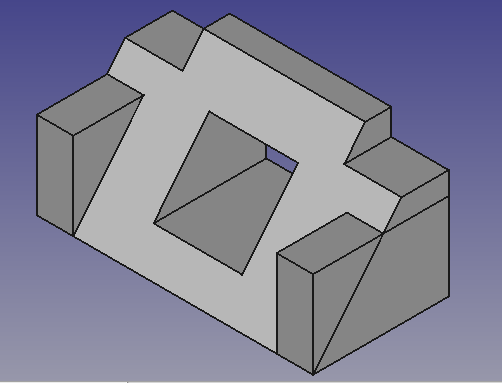
Este tutorial apresenta ao novo usuário algumas das ferramentas e técnicas usadas na bancada Part Design. Este tutorial não é um guia completo e abrangente para a bancada Part Design e muitas das ferramentas e recursos não são abordados. Este tutorial guiará o usuário pelas etapas necessárias para modelar a peça mostrada na imagem abaixo usando esboços.
Aqui um vídeo de toda a construção: https://youtu.be/geIrH1cOCzc
(cada seção tem seu próprio vídeo abaixo)
Antes de começar
A tarefa
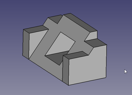
Neste tutorial você usará a bancada Part Design para criar um modelo sólido 3D da peça mostrada no Desenho abaixo. Todas as dimensões necessárias para completar esta tarefa são dadas. Você começará criando uma forma central a partir de um esboço básico e, em seguida, construirá nessa forma, adicionando o que é conhecido como recursos. Esses recursos adicionarão ou removerão material do sólido por meio do uso de esboços adicionais e operações de recurso que os acompanham. Este tutorial não usará todos os recursos e ferramentas disponíveis na bancada Part Design, mas deve usar o suficiente para fornecer ao usuário deste tutorial uma base básica sobre a qual construir seus conhecimentos e habilidades.
A peça

Construindo a peça
Começo
Primeiro comece certificando-se de que você está na bancada Part Design. Uma vez lá, você deverá criar um novo documento, caso ainda não o tenha feito. É um bom hábito salvar seu trabalho com frequência, portanto, antes de mais nada, salve o novo documento, dando-lhe o nome que desejar.
Todo trabalho em Part Design começa com um Body (corpo). Em seguida, construiremos o sólido dentro do corpo começando com um Sketch (esboço).
- Clique em
 Criar corpo para criar e ativar um novo corpo. Nota: esta etapa pode ser omitida. Ao criar um esboço, se nenhum existente for encontrado, um novo será automaticamente criado e ativado.
 - Clique em
 Criar novo esboço. Isso criará o esboço dentro do corpo recém-criado.
 - Precisamos definir onde o esboço (Sketch) será anexado. Vamos anexá-lo a um plano da Origem do corpo (Body).
- Na aba Tarefas da Tela combinada, selecione YZ_Plane na lista e pressione OK:
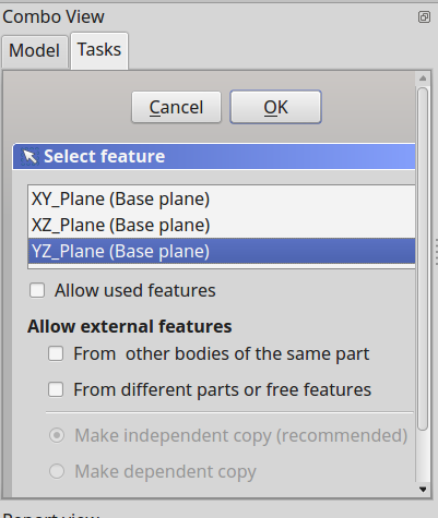
Observação: é possível que o botão OK não esteja visível se o painel lateral não for largo o suficiente. Você pode aumentá-lo arrastando sua borda direita. Coloque o ponteiro do mouse sobre a borda; quando o ponteiro mudar para uma seta de duas direções, pressione e segure o botão esquerdo do mouse e arraste.
Depois de clicar em OK, o FreeCAD muda automaticamente para a bancada Sketcher e abre o esboço no modo de edição:
Crie o esboço
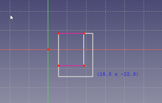
Em seguida, use a ferramenta ![]() Polyline e fazça uma forma mais ou menos como a da próxima imagem. Não precisa ser perfeito, pois a forma final é alcançada com restrições. Depois de ter a forma básica, começaremos a aplicar as restrições. Se as "Restrições automáticas" estavam ativadas, algumas dessas restrições foram aplicadas automaticamente, caso contrário, faça os próximos procedimentos, mas primeiro certifique-se de ter saído da ferramenta Polyline clicando com o botão direito do mouse ou pressionando ESC duas vezes. O cursor do mouse deve voltar de uma cruz para o cursor de seta padrão. Não pressione ESC uma terceira vez ou você sairá do modo de edição. Se isso acontecer, clique na aba Modelo e, em seguida, clique duas vezes no elemento Sketch na árvore ou clique nele com o botão direito do mouse e selecione Editar esboço no menu de contexto. Para evitar sair do modo de edição ao pressionar Esc com muita frequência, altere a preferência Esc pode sair do modo de edição de esboço (introduced in version 0.19), consulte Preferências Sketcher.
Polyline e fazça uma forma mais ou menos como a da próxima imagem. Não precisa ser perfeito, pois a forma final é alcançada com restrições. Depois de ter a forma básica, começaremos a aplicar as restrições. Se as "Restrições automáticas" estavam ativadas, algumas dessas restrições foram aplicadas automaticamente, caso contrário, faça os próximos procedimentos, mas primeiro certifique-se de ter saído da ferramenta Polyline clicando com o botão direito do mouse ou pressionando ESC duas vezes. O cursor do mouse deve voltar de uma cruz para o cursor de seta padrão. Não pressione ESC uma terceira vez ou você sairá do modo de edição. Se isso acontecer, clique na aba Modelo e, em seguida, clique duas vezes no elemento Sketch na árvore ou clique nele com o botão direito do mouse e selecione Editar esboço no menu de contexto. Para evitar sair do modo de edição ao pressionar Esc com muita frequência, altere a preferência Esc pode sair do modo de edição de esboço (introduced in version 0.19), consulte Preferências Sketcher.
NOTE: Since this tutorial was written there have been improvements to the sketcher solver, if it detects a redundant constraint it will turn the sketch orange in colour, and before further constraints are added, the redundant constraint should be removed. (The redundant constraint is shown in the Task view, click on the blue reference and press delete.)
- Select the two horizontal lines with your mouse by clicking on them, and once selected, click on the
 horizontal constraint.
 - Select the vertical line on the right and then click on the
 vertical constraint.
 - Select the start and end points of your polyline and click on the
 coincident constraint to close the polyline.
 - Select the bottom horizontal line and the right vertical line and apply and
 equal constraint.
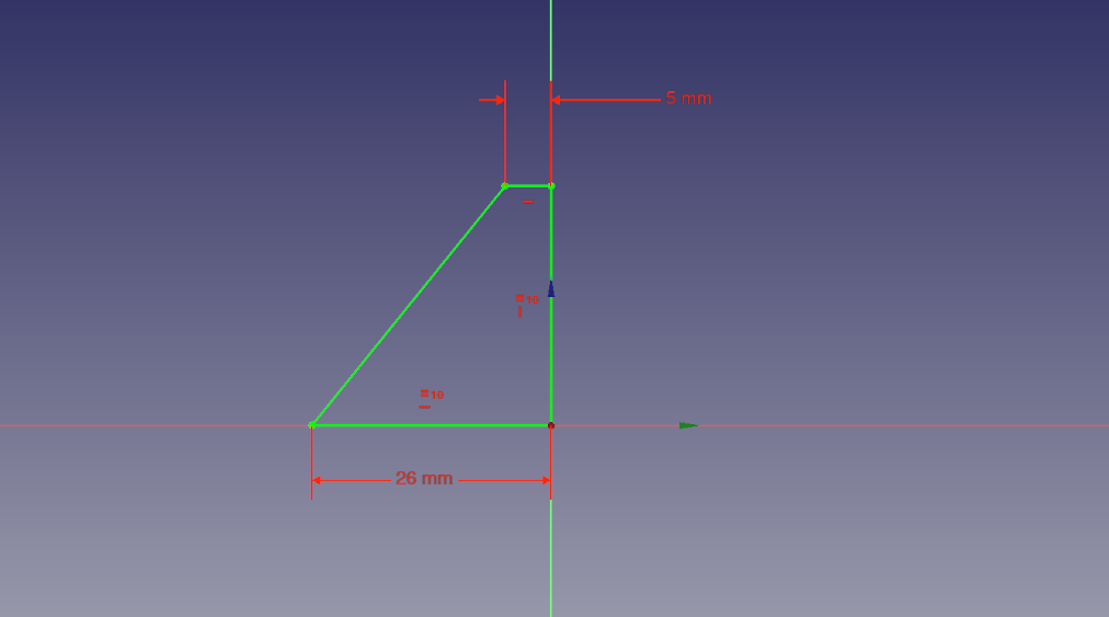
 - Select either the horizontal or vertical line and apply either a corresponding
 horizontal distance constraint or
  vertical distance constraint and give it a value of 26 mm.
 - Select the top horizontal line and apply the horizontal distance constraint and give it a value of 5 mm
- Select the lower right point (vertex) of the horizontal line Origin and then the center point of the grid and apply the coincident constraint to fix your shape.
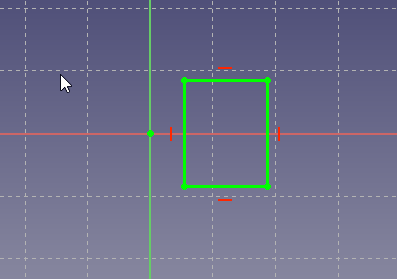
At this point you should have a fully constrained sketch as indicated by it changing color and the message shown in the Combo View. It should now look just like the image below.
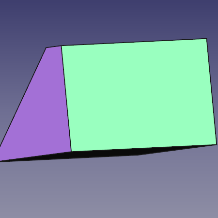
Now in the Tasks tab, click on the Close button to leave the sketch edit mode and select ![]() Pad from the toolbar or from the Part Design menu. This will give you a Pad dialog in the Task View. Using that dialog, first using the Type pulldown menu, select Two dimensions. Drawing presented at the beginning of this tutorial says the part is 53 mm long. We do it by Padding our sketch both ways from the center plane to make up that distance i.e. make the pad symmetric in relation of sketch-plane. The reason for is seen later when creating features. For now, given we want it to be 53 mm long in total we will input 26.5 for Length, and 26.5 again for the Second length. Alternatively, you can provide a single length of 53 mm and click the Symmetric to plane check box. Once that is done we now have our base solid upon which we will add additional features to construct our part.
Pad from the toolbar or from the Part Design menu. This will give you a Pad dialog in the Task View. Using that dialog, first using the Type pulldown menu, select Two dimensions. Drawing presented at the beginning of this tutorial says the part is 53 mm long. We do it by Padding our sketch both ways from the center plane to make up that distance i.e. make the pad symmetric in relation of sketch-plane. The reason for is seen later when creating features. For now, given we want it to be 53 mm long in total we will input 26.5 for Length, and 26.5 again for the Second length. Alternatively, you can provide a single length of 53 mm and click the Symmetric to plane check box. Once that is done we now have our base solid upon which we will add additional features to construct our part.
A video of the steps used in this portion of the tutorial is here: https://youtu.be/cUyPnCMeTgg
Features with pocket and external geometry
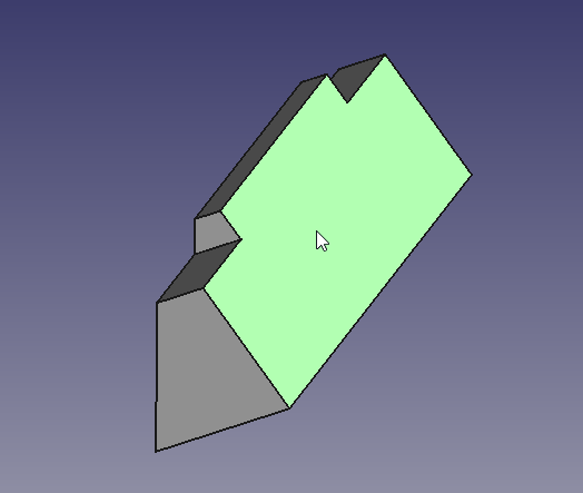
Using the mouse or the view icons turn the model around so you can see its back. Once the back of the part is visible, select the back face by clicking on it as seen in the next image.
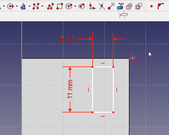
After the face is selected, click on the New sketch icon in the toolbar or from the Part Design menu and that will map our next sketch to the back face of the part. Now select ![]() Rectangle tool and place a rectangle on the rear face of the part in a similar fashion as shown below. Now following the steps listed, constrain the sketch.
Rectangle tool and place a rectangle on the rear face of the part in a similar fashion as shown below. Now following the steps listed, constrain the sketch.
- Select one of the horizontal lines apply a horizontal distance constraint and a value of 5 mm.
- Select one of the vertical lines and give it a vertical distance constraint and a value of 11 mm.
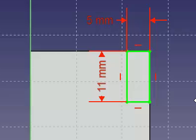
- Select
 External geometry tool
 - Select the upper right vertex of the face and click it so you are provided a point from the external geometry to link our sketch to.
- Right click to end the External geometry mode
- Select that point you just made available with the External geometry tool and then select the upper right vertex of the rectangle and click on the Constrain coincident. At this point the sketch should be fully constrained and look like the next image.
Once that is done, click the Close button at the top of the Tasks tab in the Combo View window, then select ![]() Pocket tool from the toolbar or Part Design menu. Using this tool is the opposite of the Pad tool. As the Pad tool adds material to the part, the Pocket tool removes material from the part. Both operations are called features. In this Pocket operation we want to select Through all from the type pulldown-menu and then click the OK button.
Pocket tool from the toolbar or Part Design menu. Using this tool is the opposite of the Pad tool. As the Pad tool adds material to the part, the Pocket tool removes material from the part. Both operations are called features. In this Pocket operation we want to select Through all from the type pulldown-menu and then click the OK button.
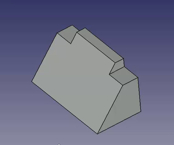
For the next operation, make sure that “Pocket” is selected in the Model tree view and once done, click on the ![]() Mirror feature on the toolbar or from the Part Design menu. In the Mirror dialog in the Combo View, select Horizontal sketch axis from the Plane pulldown menu. Then click OK. The Mirror feature works in this way because the base feature of our model was Padded both ways from the horizontal plane in the first operation with the base sketch. If all has gone well, you should now have a part that looks like the image below after you orbit it around to the front.
Mirror feature on the toolbar or from the Part Design menu. In the Mirror dialog in the Combo View, select Horizontal sketch axis from the Plane pulldown menu. Then click OK. The Mirror feature works in this way because the base feature of our model was Padded both ways from the horizontal plane in the first operation with the base sketch. If all has gone well, you should now have a part that looks like the image below after you orbit it around to the front.
A video of the steps used in this portion of the tutorial is here: https://youtu.be/wiGXV9G7mrM
Features with pad and external geometry
After taking a look, orbit back around and once again select the back face of the part and select that face to map the next sketch to.
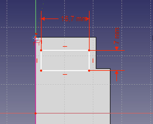
Select New sketch and make a new rectangle in the manner similar to what is shown below in the next image. Then proceed to add dimensional constraints to the rectangle.
- Select a horizontal line and apply a horizontal distance constraint with a value of 16.7.
- Select a vertical line and apply a vertical distance constraint of 7 mm
- Using the External geometry tool, select the upper left vertex of the part face.
Now selecting the upper left vertex of the rectangle and the external geometry point, click on the coincident constraint to fully constrain the sketch.
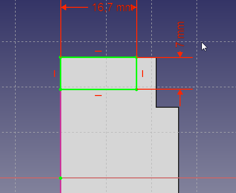
Close the Sketcher.
Next we will click on the Pad feature and in the Pad dialog in the Combo View we want a length of 26 mm leaving the type as Dimension and then placing a check on the Reversed checkbox. Using the Reversed checkbox will cause the Pad to go into the part instead of away from the part. This operation provides with the following result.
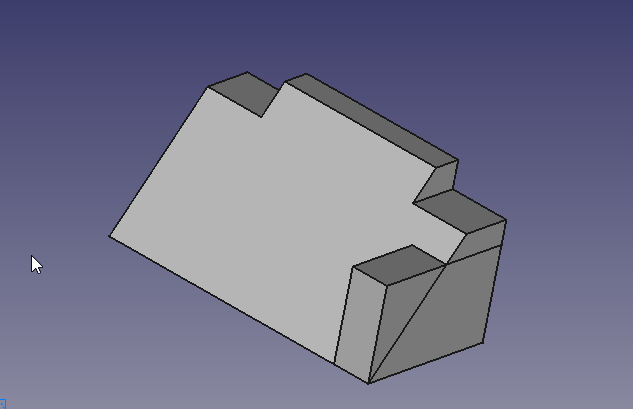
Once again use the Mirror feature to get the second pad. First ensure that created Pad is selected in the tree view, then click on Mirror in the toolbar or select it from the Part Design menu. We will repeat the operation we did for Pocket above and select Horizontal sketch axis from the Plane pulldown menu.
A video of the steps used in this portion of the tutorial is here: https://youtu.be/Ido1owp8ubc
Feature with pocket and external geometry
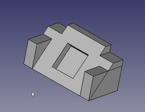
At this point orbiting the part around to the front, we can see that our part is now starting to look like the part in the dimensioned drawing at the beginning of this tutorial. Once you have the view of the front, click on the sloped face with your mouse to select the face we will use for the next sketch.

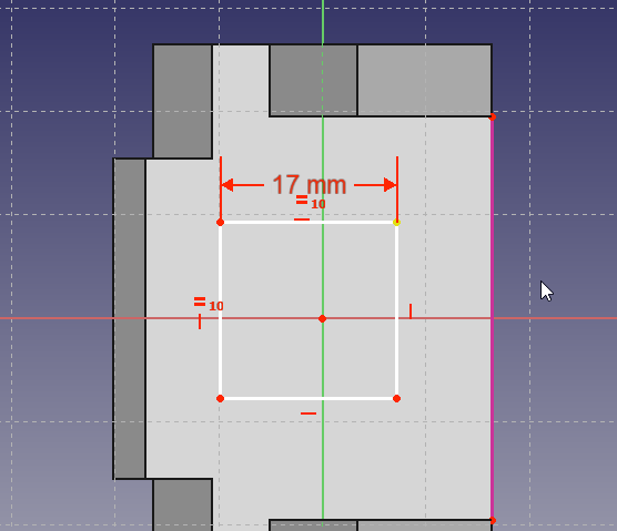
Here we will use the Rectangle tool and place a rectangle in our sketch and once having done so, apply the following constraints.
- Select a horizontal line and a vertical line, and after both are selected, click on the Equals constraint.
- Select either a horizontal or vertical line and apply a corresponding horizontal or vertical distance constraint with a value of 17 mm
- Using the External geometry tool, select the top right vertex as shown in the image below.
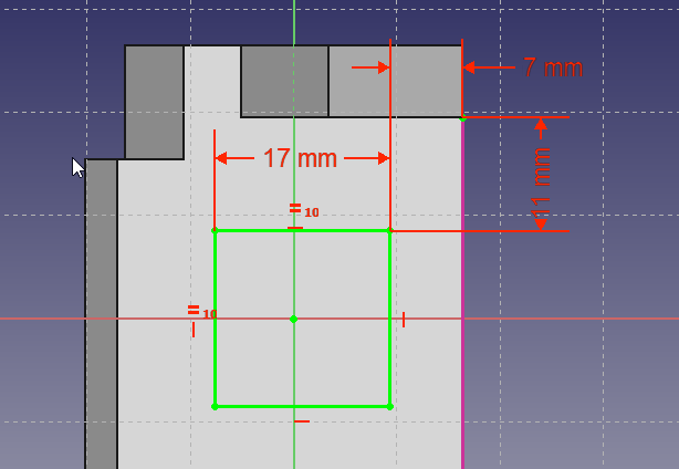
Now using the dimensions from the drawing, apply the following constraints.
- Select the external geometry point and the upper right vertex of the now square sketch and apply a horizontal distance constraint of 7 mm
- Select the external geometry point and the upper right vertex of the now square sketch and apply a vertical distance constraint of 11 mm
The result should be as follows.
At this point if we were to simply Pocket this sketch, the resulting hole would be perpendicular to the sloped face that it is mapped to, and this is not what we want.
We want the hole to be perpendicular to the back face, but it's projected dimensions are not the 17 mm x 17 mm dimensions that are given in the drawing. Now we could do the math and calculate the dimensions needed, or we can use the tools provided in FreeCAD to make that projection for us.
A video of the steps used in this portion of the tutorial is here: https://youtu.be/x4d5nZPWCLQ
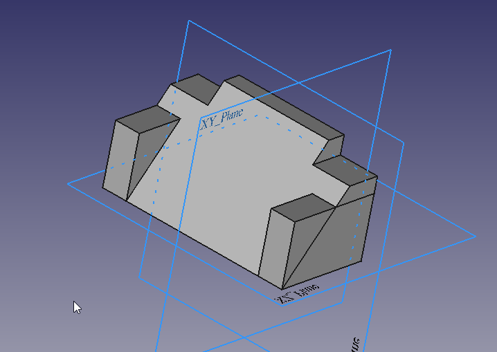
To create pocket which has the sloped rectangle as it´s outlet, we draw a new rectangle on the rear side, using the projection of the sloped rectangle as an external reference. Orbit the Solid around to see the rear face of the part once again and select the back face to map the final sketch to.
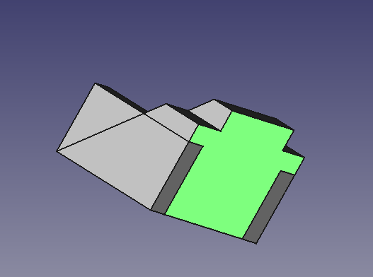
Select ![]() New Sketch from the toolbar or Part Design menu. Now in sketch edit mode, we do not see the sketched rectangle on the slope. To make it selectable , we switch the combo view to model tab and select the last sketch made (Sketch003) on the sloped plane. Then using the spacebar, make it visible. Next, select the mirror feature above (mirrored001) and again using the spacebar, hide it. Then you should see the sloped rectangle inside the 3D View. You may continue to work with the model tab visible, or switch back to tasks tab. Using the
New Sketch from the toolbar or Part Design menu. Now in sketch edit mode, we do not see the sketched rectangle on the slope. To make it selectable , we switch the combo view to model tab and select the last sketch made (Sketch003) on the sloped plane. Then using the spacebar, make it visible. Next, select the mirror feature above (mirrored001) and again using the spacebar, hide it. Then you should see the sloped rectangle inside the 3D View. You may continue to work with the model tab visible, or switch back to tasks tab. Using the ![]() External geometry tool, select the upper and lower horizontal edges of the sloped rectangle. Then, add a new rectangle to the sketch using the
External geometry tool, select the upper and lower horizontal edges of the sloped rectangle. Then, add a new rectangle to the sketch using the ![]() Rectangle tool.
Rectangle tool.
- Select the upper left vertex of the new rectangle and the upper left point of the external geometry and click on the coincident constraint.
- Click on the lower right vertex of the new rectangle and the lower right point of the external geometry and click on the coincident constraint.
And we should end up with this.
For the final step in this tutorial, close the sketcher window using close or finish editing from the context menu of sketch004 and then select the ![]() Pocket feature from the toolbar or from the Part Design menu. From the Type pulldown select Through all and click the OK button.
Pocket feature from the toolbar or from the Part Design menu. From the Type pulldown select Through all and click the OK button.
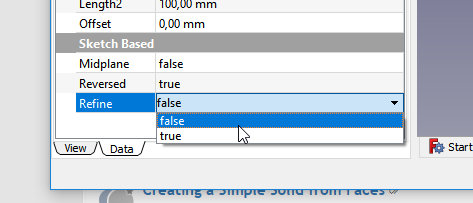
At this point, you will see some lines which come from intersecting features. In this case the side block intersects with the base profile letting it appear as a triangular block above the profile (i.e., there is an extra line visible in the above picture on the right face of the model). To remove these lines, you can either switch on "refine shape" in your Part Design Settings or, to save some processing speed and still have these lines while constructing, individually switch it on at each feature. The Setting on feature level can be done in the "data" tab of the feature. Set the refine property to TRUE for the pocket feature Pocket001 to invoke refining.
A video of these steps of the tutorial is here: https://youtu.be/UYI0gvxCYeI
This tutorial and your model are complete.
Additional Resources
- FreeCAD file for comparison (made with 0.17) Download
- Structure tools: Part, Group
- Helper tools: Create body, Create sketch, Attach sketch, Edit sketch, Validate sketch, Check geometry, Create a shape binder, Create a sub-object(s) shape binder, Create a clone, Create a datum plane, Create a datum line, Create a datum point, Create a local coordinate system
- Modeling tools:
- Additive tools: Pad, Revolution, Additive loft, Additive pipe, Additive helix, Additive box, Additive cylinder, Additive sphere, Additive cone, Additive ellipsoid, Additive torus, Additive prism, Additive wedge
- Subtractive tools: Pocket, Hole, Groove, Subtractive loft, Subtractive pipe, Subtractive helix, Subtractive box, Subtractive cylinder, Subtractive sphere, Subtractive cone, Subtractive ellipsoid, Subtractive torus, Subtractive prism, Subtractive wedge
- Boolean: Boolean operation
- Dress-up tools: Fillet, Chamfer, Draft, Thickness
- Transformation tools: Mirrored, Linear Pattern, Polar Pattern, Create MultiTransform, Scaled
- Extras: Sprocket, Involute gear, Shaft design wizard
- Context menu: Set tip, Move object to other body, Move object after other object, Appearance, Color per face
- Preferences: Preferences, Fine tuning
- General: Create sketch, Edit sketch, Attach sketch, Reorient sketch, Validate sketch, Merge sketches, Mirror sketch, Leave sketch, View sketch, View section, Toggle grid, Toggle snap, Configure rendering order, Stop operation
- Sketcher geometries: Point, Polyline, Line, Arc, Arc by 3 points, Arc of ellipse, Arc of hyperbola, Arc of parabola, Circle, Circle by 3 points, Ellipse, Ellipse by 3 points, Rectangle, Centered rectangle, Rounded rectangle, Triangle, Square, Pentagon, Hexagon, Heptagon, Octagon, Regular polygon, Slot, Arc slot, B-spline by control points, Periodic B-spline by control points, B-spline by knots, Periodic B-spline by knots, Toggle construction geometry
- Sketcher constraints:
- Dimensional constraints: Dimension, Horizontal distance, Vertical distance, Distance, Auto radius/diameter, Radius, Diameter, Angle, Lock
- Geometric constraints: Coincident (unified), Coincident, Point on object, Horizontal/vertical, Horizontal, Vertical, Parallel, Perpendicular, Tangent or collinear, Equal, Symmetric, Block
- Other constraints: Refraction (Snell's law)
- Constraint tools: Toggle driving/reference constraint, Activate/deactivate constraint
- Sketcher tools: Fillet, Chamfer, Trim, Split, Extend, External geometry, Carbon copy, Select origin, Select horizontal axis, Select vertical axis, Array transform, Polar transform, Scale transform, Offset geometry, Symmetry, Remove axes alignment, Delete all geometry, Delete all constraints
- Sketcher B-spline tools: Convert geometry to B-spline, Increase B-spline degree, Decrease B-spline degree, Increase knot multiplicity, Decrease knot multiplicity, Insert knot, Join curves
- Sketcher visual: Select unconstrained DoF, Select associated constraints, Select associated geometry, Select redundant constraints, Select conflicting constraints, Show/hide circular helper for arcs, Show/hide B-spline degree, Show/hide B-spline control polygon, Show/hide B-spline curvature comb, Show/hide B-spline knot multiplicity, Show/hide B-spline control point weight, Show/hide internal geometry, Switch virtual space
- Additional: Sketcher Dialog, Preferences, Sketcher scripting
- Getting started
- Installation: Download, Windows, Linux, Mac, Additional components, Docker, AppImage, Ubuntu Snap
- Basics: About FreeCAD, Interface, Mouse navigation, Selection methods, Object name, Preferences, Workbenches, Document structure, Properties, Help FreeCAD, Donate
- Help: Tutorials, Video tutorials
- Workbenches: Std Base, Assembly, BIM, CAM, Draft, FEM, Inspection, Material, Mesh, OpenSCAD, Part, PartDesign, Points, Reverse Engineering, Robot, Sketcher, Spreadsheet, Surface, TechDraw, Test Framework
- Hubs: User hub, Power users hub, Developer hub