CAM Walkthrough for the Impatient/ru
 Руководство Руководство
|
| Тема |
|---|
| Верстак CAM |
| Уровень |
| Начинающий/Средний |
| Время для завершения |
| 15 минут |
| Авторы |
| Chrisb |
| FreeCAD версия |
| 0.19 |
| Примеры файлов |
| Смотрите также |
| None |
Цель
Демонстрация создания Задания  верстака Path на основе 3D-модели. Затем генерируем правильный диалект G-кода для целевого фрезерного станка с ЧПУ.
3D Модель
1. Проект начинается с простой модели в FreeCAD, созданной в  Part Design — куб с прямоугольным карманом,

Above: Created in the
 Part Design включая корпус, короб с карманом, основанный на эскизе, ориентированном в
  XY-plane.
2. После того как 3D-модель готова, переключитесь на  CAM Workbench через выбор рабочей панели (выпадающее меню)
Задание
3. Теперь создаём Задание CAM одним из следующих способов:
- Нажатием кнопки
 Задание на панели инструментов.
 - Используя последовательно клавиши P и J.
- Используя пункт Траектория → Задание в верхнем меню.

Выше: диалоговое окно Создать Задание CAM
4. Это откроет диалог создания задания. В этом диалоге нажмите OK, чтобы принять Body в качестве основной модели, без шаблона.
Настройка Задания
5. Окно редактирования задания открывается в окне задач, а окно просмотра модели показывает заготовку в виде каркасного куба вокруг основной детали. Вкладка Настройка выбрана.
Результат выполнения задания
6. The Output tab defines the output file path, name, extension, and the Postprocessor. For advanced users, Post Processor Arguments can be customized (mouse over to show tooltips of common arguments).
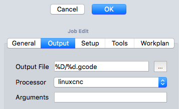
Above: CAM Job Edit dialog with the Output tab selected

Job Tools
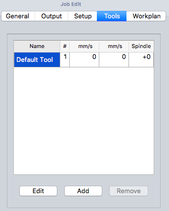
Above: CAM Job Edit dialog with the Tools tab selected

7. Modify the Default tool by selecting it and clicking the Edit button. This opens the Tool Controller edit window.
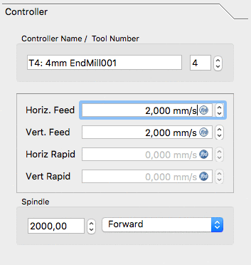
Above: CAM Job Tool Controller subpanel Edit dialog

8. The name given to the tool and the tool number correspond with the tool number of the machine. In the dialog (see above) it's Tool Nr. 4. The tool controller is configured for horizontal and vertical feed rates of 2mm/s and a spindle speed of 2000 rpm.
9. Select the Tool subpanel of the Tool controller. Set the diameter (and if you wish to use the  CAM Simulation tool later: add a cutting edge angle and cutting edge height).
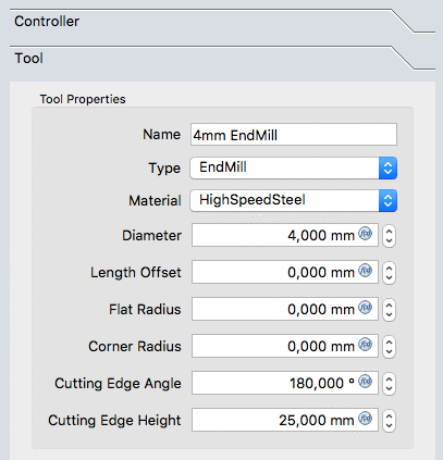
Above: CAM Job Tool controller 'Tool' subpanel dialog

10. The values are confirmed with OK
Note: For easy access, all the tools can be predefined and selected from the  Tool manager.
Job Workplan
The Workplan tab initially is shown as empty. It is then populated by the sequence of Job Operations, Partial CAM Commands, and CAM Dressups. The sequence of these items is ordered here.
This tree is shown after the Job's configuration once the CAM Job is unfolded:

The Path Operations
11. Two operations will be added to generate milling paths for this CAM Job. The Profile operation creates a path around the box and the Pocket operation creates a path for the inner pocket.
12. For now we will keep it simple. The  Profile button opens the Contour panel. After confirming with OK using the default values, see the green path around the object is visible.
13. Selecting the bottom of the pocket and then the  Pocket button opens the Pocket Shape window. The default values for Base Geometry, Depths, and Heights are used, and the Operation subpanel is selected, and the Step Over Percent is set at 50.
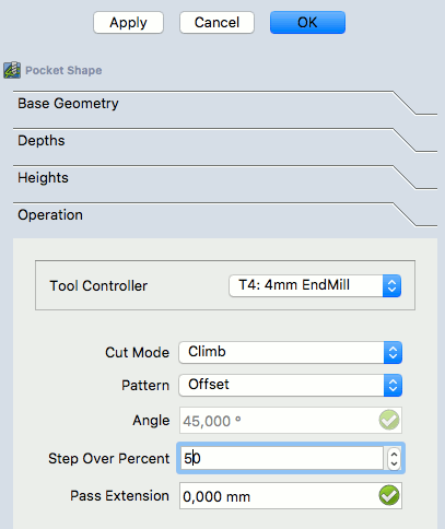
Above: Pocket Shape dialog with the Operation subpanel selected

14. The pattern is changed to "Offset" and the Job Operation is confirmed for the pocket configuration with OK
The result is a model with two paths:
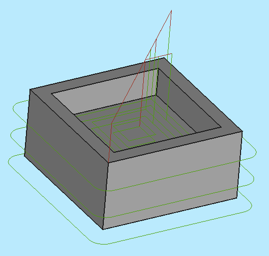
Above: resulting with a model with two paths

Verifying Paths
There are two ways to verify the created paths. The G-Code can be inspected, including highlighting the corresponding path segments. The milling process of the CAM Job can also be simulated to demonstrate the idealized tool paths, required for the Tool geometries to mill the Stock.
To inspect the G-Code use the  CAM Inspect tool. Selecting the corresponding G-Code lines within the G-Code Inspection window highlights individual path segments.
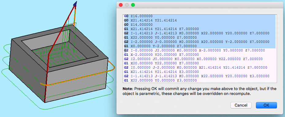
Above: CAM Inspection tool opens the G-Code Inspection dialog

To start the simulation use the  CAM Simulator tool.
Adjust speed and accuracy and start the simulation with the  (Play) button.
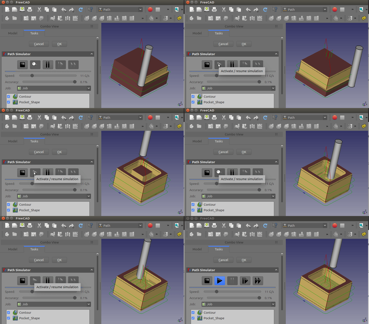
Above: CAM Simulation in progress

If you want to end the simulation click the Cancel button, it will remove the stock created for the simulation. If you click OK this object will be kept in your Job.
Postprocess the Job
The final step to generate G-Code for the target mill is to postprocess the Job. This outputs the G-Codes to a file that can be uploaded to the target CNC machine controller. To invoke the Postprocessor:
- Select the Job object in the Tree View
- Select the
 CAM Postprocessing tool to postprocess the file. This opens a G-Code window allowing inspection of the final output file before it is saved.

Above: G-Code window allowing inspection of the final output file

CAM
- Project Commands: New Job, Post Process, Sanity Check, Export Template
- Tool Commands: Inspect Toolpath, Legacy CAM Simulator, CAM Simulator, Finish Selecting Loop, Toggle Operation, ToolBit Library Manager, Add toolbit…
- Basic Operations: Profile, Pocket Shape, Face, Helix, Adaptive, Slot, Drilling, Tapping, Engrave, Deburr, Vcarve
- 3D Operations: 3D Pocket, 3D Surface, Waterline
- CAM Dressup: Array, Axis Map, Boundary, Dogbone, Drag Knife, Lead In/Out, Ramp Entry, Tag, Z Depth Correction
- Supplemental Commands: Comment, Stop, Custom, Probe, Path From Shape TC
- CAM Modification: Copy oOperation, Array, Simple Copy
- Specialty Operations: Thread Milling
- Miscellaneous: Area, Area Workplane
- ToolBit architecture: Tools, ToolShape, ToolBit, ToolBit Library, ToolController
- Additional: Preferences, Scripting
 Документация пользователя
- Начинающим
- Установка: Загрузка, Windows, Linux, Mac, Дополнительных компонентов, Docker, AppImage, Ubuntu Snap
- Базовая: О FreeCAD, Интерфейс, Навигация мыши, Методы выделения, Имя объекта, Настройки, Верстаки, Структура документа, Свойства, Помоги FreeCAD, Пожертвования
- Помощь: Учебники, Видео учебники
- Верстаки: Std Base, Arch, Assembly, CAM, Draft, FEM, Inspection, Mesh, OpenSCAD, Part, PartDesign, Points, Reverse Engineering, Robot, Sketcher, Spreadsheet, Surface, TechDraw, Test Framework