Scripted Parts: Ball Bearing - Part 2/ru
| Тема |
|---|
| Part Scripting - Ball Bearing #2 |
| Уровень |
| Beginner |
| Время для завершения |
| 30 min |
| Авторы |
| r-frank |
| FreeCAD версия |
| 0.16.6706 |
| Примеры файлов |
| Смотрите также |
| None |
Introduction
This tutorial is meant as a beginner's introduction to creating parts with python scripts within FreeCAD.
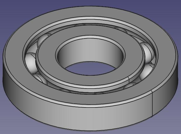
This tutorial will cover how to build a ball bearing with a workflow that consists of creating sketches and revolving them.
The code will produce a new FreeCAD document with 12 shapes (Inner Ring, Outer Ring and 10 balls/spheres).
It will look like this:
Workflow
The workflow is more or less identical how you would create the part in part design workbench.
Just some small differences.
- Create a new empty document and make it the active document
- Draw the basic shape of the outer ring consisting of four straight lines and four arcs

- Connect the lines and arcs and upgrade them to one single wire
- Upgrade the wire to a face
- Revolve the face to get a shape
- Draw a circle
- Upgrade circle to wire
- Upgrade wire to face
- Revolve face and apply boolean cut to obtain groove in outer ring
- Draw the basic shape of the inner ring consisting of four straight lines and four arcs
- Connect the lines and arcs and upgrade them to one single wire
- Upgrade the wire to a face
- Revolve the face to get a shape
- Draw a circle
- Upgrade circle to wire
- Upgrade wire to face
- Revolve face and apply boolean cut to obtain groove in inner ring
- Insert balls with same workflow as in part 1 (because of effectiveness)
- Set view to axometric
- Zoom to fit all
Making the groove
Drawing an arc needs either three points or a start angle and an end angle.
In the sketcher we would use constraints to define the start point and the end point of the arc.
Since we can't do this in scripting, we draw a rounded rectangle and revolve it to get a basic "ring shape".
Then we draw a circle and revolve it to get the geometry of the groove.
Then we apply a boolean cut to the two revolved shapes and we have the complete shape of the inner/outer ring.
Inserting the balls
The correct sketcher-based workflow of inserting the balls would be:
- Draw an arc (semi-circle) with center being identical with the origin and draw a line closing the "open" side of the arc
- Convert the two elements to a wire, upgrade to a face, revolve around z-axis to get a ball shape
- Use "translate" command to move the ball into correct position
- Repeat the above steps nine times involving math function to create and position the other balls
- This repeat-operation could be programmed with a loop
Now this is not effective, inserting primitives and positioning them is easier and faster in this case.
So we use the same method as in "Scripted Parts: Ball Bearing - Part 1".
Links
Scripted objects: The wiki page explaining the basics of scripting
Topological data scripting: A tutorial for covering basics of scripting
Scripted Parts: Ball Bearing - Part 1: Doing it with part primitives
Bearings from scripted sketches: Base for this tutorial, thanks to JMG ...
Code
## Ball-bearing script
## 11.08.2016 by r-frank (BPLRFE/LearnFreeCAD on Youtube)
## based on ball bearing script by JMG
## (http://linuxforanengineer.blogspot.de/2013/12/bearings-from-scripted-sketches.html)
#
#needed for doing boolean operations
import Part
#needed for calculating the positions of the balls
import math
#needed for translation and rotation of objects
from FreeCAD import Base
#
#VALUES#
#(radius of shaft/inner radius of inner ring)
R1=15.0
#(outer radius of inner ring)
R2=25.0
#(inner radius of outer ring)
R3=30.0
#(outer radius of outer ring)
R4=40.0
#(thickness of bearing)
TH=15.0
#(number of balls)
NBall=10
#(radius of ball)
RBall=5.0
#(rounding radius for fillets)
RR=1
#first coordinate of center of ball
CBall=((R3-R2)/2)+R2
#second coordinate of center of ball
PBall=TH/2
#
#Create new document
App.newDocument("Unnamed")
App.setActiveDocument("Unnamed")
#
#Lines for basic shape of outer ring
L1o=Part.makeLine((R4,0,TH-RR),(R4,0,RR))
L2o=Part.makeLine((R4-RR,0,0),(R3+RR,0,0))
L3o=Part.makeLine((R3,0,RR),(R3,0,TH-RR))
L4o=Part.makeLine((R3+RR,0,TH),(R4-RR,0,TH))
#Corner rounding for basic shape of outer ring
A1o=Part.makeCircle(RR,Base.Vector(R4-RR,0,RR),Base.Vector(0,1,0),0,90)
A2o=Part.makeCircle(RR,Base.Vector(R3+RR,0,RR),Base.Vector(0,1,0),90,180)
A3o=Part.makeCircle(RR,Base.Vector(R3+RR,0,TH-RR),Base.Vector(0,1,0),180,270)
A4o=Part.makeCircle(RR,Base.Vector(R4-RR,0,TH-RR),Base.Vector(0,1,0),270,360)
#Connect Lines and arcs to make wire and upgrade to face, revolve and apply cut to obtain groove
OR=Part.Wire([L1o,A1o,L2o,A2o,L3o,A3o,L4o,A4o])
OR=Part.Face(OR)
OR=OR.revolve(Base.Vector(0,0,1),Base.Vector(0,0,360))
C1=Part.makeCircle(RBall,Base.Vector(R2+(R3-R2)/2,0,TH/2),Base.Vector(0,1,0),0,360)
GRo=Part.Wire([C1])
GRo=Part.Face(GRo)
GRo=GRo.revolve(Base.Vector(0,0,1),Base.Vector(0,0,360))
OR=OR.cut(GRo)
Part.show(OR)
#
#Lines for basic shape of inner ring
L1i=Part.makeLine((R2,0,TH-RR),(R2,0,RR))
L2i=Part.makeLine((R2-RR,0,0),(R1+RR,0,0))
L3i=Part.makeLine((R1,0,RR),(R1,0,TH-RR))
L4i=Part.makeLine((R1+RR,0,TH),(R2-RR,0,TH))
#Corner rounding for basic shape of inner ring
A1i=Part.makeCircle(RR,Base.Vector(R2-RR,0,RR),Base.Vector(0,1,0),0,90)
A2i=Part.makeCircle(RR,Base.Vector(R1+RR,0,RR),Base.Vector(0,1,0),90,180)
A3i=Part.makeCircle(RR,Base.Vector(R1+RR,0,TH-RR),Base.Vector(0,1,0),180,270)
A4i=Part.makeCircle(RR,Base.Vector(R2-RR,0,TH-RR),Base.Vector(0,1,0),270,360)
#Connect Lines and arcs to make wire and upgrade to face, revolve and apply cut to obtain groove
IR=Part.Wire([L1i,A1i,L2i,A2i,L3i,A3i,L4i,A4i])
IR=Part.Face(IR)
IR=IR.revolve(Base.Vector(0,0,1),Base.Vector(0,0,360))
C2=Part.makeCircle(RBall,Base.Vector(R2+(R3-R2)/2,0,TH/2),Base.Vector(0,1,0),0,360)
GRi=Part.Wire([C2])
GRi=Part.Face(GRi)
GRi=GRi.revolve(Base.Vector(0,0,1),Base.Vector(0,0,360))
IR=IR.cut(GRi)
Part.show(IR)
#
#Balls#
for i in range(NBall):
  Ball=Part.makeSphere(RBall)
  Alpha=(i*2*math.pi)/NBall
  BV=(CBall*math.cos(Alpha),CBall*math.sin(Alpha),TH/2)
  Ball.translate(BV)
  Part.show(Ball)
#
#Make it pretty#
App.ActiveDocument.recompute()
Gui.ActiveDocument.ActiveView.viewAxometric()
Gui.SendMsgToActiveView("ViewFit")
- FreeCAD scripting: Python, Introduction to Python, Python scripting tutorial, FreeCAD Scripting Basics
- Modules: Builtin modules, Units, Quantity
- Workbenches: Workbench creation, Gui Commands, Commands, Installing more workbenches
- Meshes and Parts: Mesh Scripting, Topological data scripting, Mesh to Part, PythonOCC
- Parametric objects: Scripted objects, Viewproviders (Custom icon in tree view)
- Scenegraph: Coin (Inventor) scenegraph, Pivy
- Graphical interface: Interface creation, Interface creation completely in Python (1, 2, 3, 4, 5), PySide, PySide examples beginner, intermediate, advanced
- Macros: Macros, How to install macros
- Embedding: Embedding FreeCAD, Embedding FreeCADGui
- Other: Expressions, Code snippets, Line drawing function, FreeCAD vector math library (deprecated)
- Hubs: User hub, Power users hub, Developer hub