PartDesign NewSketch/tr
|
|
| Menü konumu |
|---|
| PartDesign → Eskiz oluştur |
| Tezgahlar |
| PartDesign |
| Varsayılan kısayol |
| Hiçbiri |
| Versiyonda tanıtıldı |
| 0.17 |
| Ayrıca bkz |
| Hiçbiri |
Tanım
Bu araç yeni bir eskiz oluşturur, mevcut değilse taslak içeren yeni bir Cisim oluşturur ve oluşturulduktan sonra Eskiz tezgahını otomatik olarak açar.
Parça tasarım tezgahını kullanarak modeller oluştururken , bu araç Eskiz tezgahında bulunan Eskiz Oluştur aracına tercih edilmelidir .
Nasıl kullanılır
- Parça tasarım araç çubuğunda
 tuşuna basınız.
 - Görevler panelinde, Özellik seç diyalogu açılır. Listede veya daha iyi görünürlük için yeniden yönlendirilebilecek 3D görünümündeki düzlemlerden birini seçin.
- Tamam tuşuna basın.
- Arayüz otomatik olarak Eskiz tezgahına geçer ve eskiz düzenlenebilir. Eskizden çıktıktan sonra, arayüz Parça tasarım tezgahına geri getirilir ve eskizden önce 3D görünüm durumuna geri yüklenir.
- Alternatif olarak, eskiz oluşturulmadan önce mevcut aktif yapı üzerindeki bir düzlem veya yüz seçilebilir, bu durumda eskiz anında oluşturulur.
Seçenekler
- Mevcut bir eskiz ekini değiştirmek için Harita Modu özelliğini değiştirin.( Özellikler bkz.)
- The Select Attachment Dialog defines the attachment of a new sketch
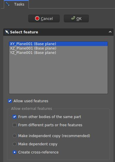
- Select Attachment dialog. These settings create a sketch on the XY-plane and allow cross-references from other items of the same body

Dialog settings
- Coordinate system box: defines the orientation of the sketch plane
- Allow used features: TBD
- Allow External Features:
- From other bodies of the same part: any elements used in the same body can be referenced
- From different parts or free features:
- Make independent copy (recommended): all other elements will be separate copies, i.e. they will not change when the original changes.
- Make dependent copy: the elements will be copies, but a dependency to the original elements is kept. This is basically using a Shapebinder
- Create cross-reference: the linked elements will not be copies, but point to the original elements, e.g. a master sketch. Any changes are reflected to this sketch
To reference any items in the Workbench Sketcher use the ![]() External Geometry and
External Geometry and ![]() CarbonCopy tools. Generally it is recommended to use other sketches as source for references rather than faces or edges, because they are less affected by the Topological Naming Issue.
CarbonCopy tools. Generally it is recommended to use other sketches as source for references rather than faces or edges, because they are less affected by the Topological Naming Issue.
Özellikler
- VeriMap Mode:Eskizin başka bir nesneye, genellikle bir düzlem veya yüze eklenme şekli, ancak başka tür nesneler olabilir. Bir ... düğmesini görmek için alana bir kez tıklayın ve Ek iletişim kutusunu açmak için basın. Devre dışı bırakıldıysa, Yerleşim özelliği etkindir.
- VeriPlacement: Çizimin 3D alanda yönünü kontrol eder; yerleşime bakınız. Eskiz Harita Modu özelliği üzerinden eklenmişse devre dışı bırakılır.
- Helper tools: New Body, New Sketch, Attach Sketch, Edit Sketch, Validate Sketch, Check Geometry, Sub-Shape Binder, Clone
- Modeling tools:
- Additive tools: Pad, Revolution, Additive Loft, Additive Pipe, Additive Helix, Additive Box, Additive Cylinder, Additive Sphere, Additive Cone, Additive Ellipsoid, Additive Torus, Additive Prism, Additive Wedge
- Subtractive tools: Pocket, Hole, Groove, Subtractive Loft, Subtractive Pipe, Subtractive Helix, Subtractive Box, Subtractive Cylinder, Subtractive Sphere, Subtractive Cone, Subtractive Ellipsoid, Subtractive Torus, Subtractive Prism, Subtractive Wedge
- Boolean: Boolean Operation
- Dress-up tools: Fillet, Chamfer, Draft, Thickness
- Transformation tools: Mirror, Linear Pattern, Polar Pattern, Multi-Transform, Scale
- Additional tools: Shape Binder, Involute Gear, Sprocket, Shaft Design Wizard
- Context menu: Suppressed, Set Tip, Move Object To…, Move Feature After…
- Preferences: Preferences, Fine tuning
- Getting started
- Installation: Download, Windows, Linux, Mac, Additional components, Docker, AppImage, Ubuntu Snap
- Basics: About FreeCAD, Interface, Mouse navigation, Selection methods, Object name, Preferences, Workbenches, Document structure, Properties, Help FreeCAD, Donate
- Help: Tutorials, Video tutorials
- Workbenches: Std Base, Assembly, BIM, CAM, Draft, FEM, Inspection, Material, Mesh, OpenSCAD, Part, PartDesign, Points, Reverse Engineering, Robot, Sketcher, Spreadsheet, Surface, TechDraw, Test Framework
- Hubs: User hub, Power users hub, Developer hub