Cables CableBox
|
|
| Menu location |
|---|
| Cables → Cable Box |
| Workbenches |
| Cables |
| Default shortcut |
| C X |
| Introduced in version |
| 0.1.0 |
| See also |
| Cables Cable, Cables CableConnector, Cables SuppLines |
Description
New concept of Cable Box Preset and SuppLines child object: introduced in version 0.3.0
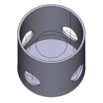
The Cable Box creates a parametric cable box object. It has default size upon creation, but some parameters, like Diameter, Height or Thickness can be changed later. The Cable Box belongs to the Arch Component class and inherits all of its properties. The Cable Box has inlet holes equipped with SuppLines crosses. Each SuppLines cross has five vertices which can be used as attachment supports for up to five cables entering single hole. SuppLines object is not a part of Cable Box shape, it is a separate child object also visible in the Tree View.
The Cable Box offers two shape types based on Circle or Rectangle DataProfile Type property. Both types allow to make parametric shapes (with small restrictions introduced for simplicity) suitable for quite accurate modeling of real cable boxes available commercially. For further simplicity and creation speed the DataPreset property has been introduced. It allows quick selection of predefined Cable Box shape from the list. There are several predefined shapes in the Cables Workbench, but the user can create their own library of boxes if desired. See Cable Box Presets for details.
Moreover, the Cable Box is equipped with two adjustable helper rings. Their purpose is to offer a temporary snapping points during editing cable subwires in Cables Edit mode to help to give them the desired shape. When not needed anymore, the helper rings can be hidden by setting DataHelper Rings Hidden property. Temporary means that helper rings should not be used as attachment support for vertexes of subwires.
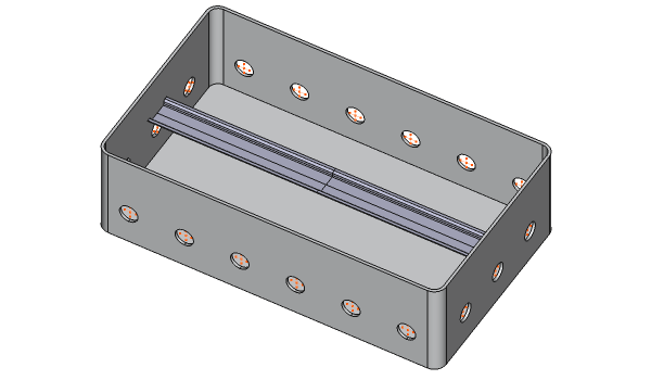
Cable Box object can be automatically equipeed with DIN TH35 rails. For details see DataDin Rails.
Cable Box object can be colored by attaching desired Material to the Material property. It supports Arch Multimaterials as well. There is a predefined boxMultiMat2m avalilable in Cables Material which is designed to support DIN rails.
Example of the default Cable Box:
There are visible SuppLines crosses inside holes and helper rings inside a box.
Example of Cable Box with DIN rail. Helper rings are hidden here.
Usage
- Select the vertex, point on surface or object in the 3D View or select nothing.
- Create Cable Box by one of these methods:
- The Cable Box task panel opens. See Options for more information.
Once created the Cable Box is placed at the position of selected vertex, point or object in the 3D space (or at the point (0,0,0) if nothing was selected).
To change already created Cable Box just double click it in the Tree View or change one of its parameters in the Property View
Options
The Cable Box preset available in the task panel can be changed. The currently selected preset is immediately visible in the 3D View.
When the special 'Customized' preset is selected, the task panel shows additional options allowing to change all the properties of a custom parametric Cable Box.
Cable Box Presets
Cables Workbench comes with several predefined shapes. However, the user is not limited to using the default set.
An additional CSV file can be created by the user, containing custom Cable Box Preset definitions. It must be named boxpresets.csv, and placed in
$FREECAD_USER_DIR/Cables/
The $FREECAD_USER_DIR can be obtained from the Python Console:
FreeCAD.getUserAppDataDir()
The contents of the custom boxpresets.csv file must be modeled upon the same rules as the boxpresets.csv in the Cables Workbench source code. The file is self descriptive and can be used as a template for own Presets creation.
The custom boxpresets.csv file can be modified without restarting FreeCAD. Any changes made there are immediately visible in the list of Presets when making a new Cable Box from the GUI.
Notes
- The SuppLines objects have reversed relation with their Cable Box parent to avoid cyclic dependencies. They are shown as a children in the Tree View only for visual organization of objects. Undesirable consequence: when the Cable Box is copied, all its child SuppLines objects must always be manually copied with it.
- Helper Rings are hidden by default. They can be easily changed by setting the DataHelper Rings Hidden property.
SuppLines child object is created automatically, its shape and placement is controlled by Cable Box.
Properties
A Cable Box object shares the common properties and behaviors of all Arch Components.
Data
Component
Some most frequently used properties from the group are described here. The rest is available at Arch Component
- DataBase (
Link): An external shape of any Shape-based base object can be used here. This will replace the default method of shape creaction and an external shape will be used. Number Of Supp Lines parameter becomes visible and can be changed if Base property is not None. Note: the SuppLines shape is still created upon properties from Cable Box group.
- DataMaterial (
Link): A Material or a MultiMaterial can be attached here. The special predefined MultiMaterialboxMultiMat2mis avalilable in Cables Material. It can be used if DIN rails are available in Cable Box object.
Cable Box
- DataBox Body Hidden (
Bool): If set totruethe box shape is hidden to make it easier to edit wires inside a box (with possible help of helper rings). It should be set tofalsewhen wires editing is finished or not needed. - DataClaim Children (
Bool): If set totrueit will claim the linked SuppLines as children in the Tree View (introduced in version 0.3.3). - DataDepth (
Length): Specifies the inner depth of the box. The default depth is 74 mm. Available if Profile Type property =Rectangle. - DataDiameter (
Length): Specifies the inner diameter of the box. The default diameter is 60 mm. Available if Profile Type property =Circle. - DataDin Rails (
Bool): If set totruethe DIN TH35 rail is added automatically to box body depending on box shape and dimensions. The rail is placed 50 mmm below the top of the box, the distance between rails is set to 125 mm. The cable box has to be big enough to allow auto creation of DIN rails. The default value istrue. Created only if Profile Type property =Rectangle. - DataFillet Radius (
Length): Specifies the inner fillet radius diameter of side walls of the box. The default fillet radius is 10 mm. Available if Profile Type property =Rectangle. - DataHeight (
Length): Specifies the inner height of the box. The default height is 62 mm. - DataHole Diameter (
Length): Specifies the diameter of a single hole. The default hole diameter is 20 mm. - DataHoles Distance (
Length): Specifies the distance between holes on a single wall. The default holes distance is 40 mm. Available if Profile Type property =Rectangle. - DataNumber Of Supp Lines (
Integer): (hidden by default) Specifies the number of a SuppLines child objects. The default value is 1. - DataPreset (
Enumeration): Specifies the predefined set of parameters for Cable Box. The default preset is1G_FlushMnt_Round_D60_h62. - DataProfile Type (
Enumeration): Specifies the type of bas profile for box shape. Available values:Circle,Rectangle. Some other properties are dependent on this one and are visible if needed. - DataShape Reference Plane (
Enumeration): The reference plane for the shape of the box. It only changes the internal reference without affecting the box Placement property (introduced in version 0.3.3). - DataThickness (
Length): Specifies the wall thickness of the box. The default thickness is 2 mm. - DataWidth (
Length): Specifies the inner width of the box. The default width is 74 mm. Available if Profile Type property =Rectangle.
Cable Box Helpers
- DataHelper Rings Hidden (
Bool): If set tofalsethe helper rings are visible. The default value istrue. Helper rings are designed to make it easier to edit wires inside a box. Helper ring vertexes can serve as temporary snapping points for cable subwires when subwires are in Cables Edit mode. This property can be set totruewhen wires editing is finished or not needed. - DataRing 1 Diameter (
Length): the diameter of helper ring 1. The default value is 45 mm. - DataRing 1 Height (
Length): the helper ring 1 height below the box lid (top open box edge). The default value is 40 mm. - DataRing 2 Diameter (
Length): the diameter of helper ring 2. The default value is 30 mm. - DataRing 2 Height (
Length): the helper ring 2 height below the box lid (top open box edge). The default value is 20 mm.
Typical workflow
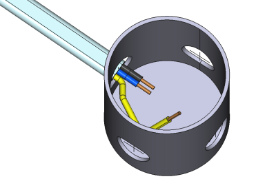
This workflow shows how to build a box with a cable attached and with one subwire of cable shaped inside a box.
- Create a Cable Box as described in Usage and set its Helper Rings Hidden property to
false. - Create Cable as described in Cable Usage with one end of a base wire attached to central vertex of one of Cable Box SuppLines crosses.
- Hide Cable shape in a Tree View e.g. by pressing SPACE key. The cable subwires should be still visible.
- Hide the Cable Box shape by setting the property Box Body Hidden to
true. The SuppLines crosses and helper rings should be still visible. - Click on the free end edge of one of cable subwires and add a vertex to it with Add Vertex. Repeat the action.
- Double click the above subwire in a Tree View to enter Cables Edit mode. Snap Endpoint should be enabled.
- Drag the newly created wire vertexes to different vertexes of helper rings. They should easily snap. Exit Cables Edit mode.
- When the desired shape of the subwire has been built, the Sub Wires Fillet Radius property of a Cable can be set e.g. to 4mm.
- Unhide Cable shape in a Tree View e.g. by pressing SPACE key.
- Unide the Cable Box shape by setting the property Box Body Hidden to
false. - Hide the helper rings shape by setting the Helper Rings Hidden property to
truein the Cable Box.
Note: At any time during subwire editing in the Cables Edit mode the height or diameter of helper ring can be changed. This can be helpful in creating new temporary reference points.
Example of cable subwire shaped inside Cable Box.
Here is the animated image showing the steps described above.


