FEM Example Capacitance Two Balls/de
| Thema |
|---|
| Finite Elemente Analyse |
| Niveau |
| Anfänger |
| Bearbeitungszeit |
| 30 min |
| Autoren |
| Sudhanshu Dubey |
| FreeCAD-Version |
| 0.19 oder höher |
| Beispieldateien |
| Programmgesteuert erstellt |
| Siehe auch |
| None |
Einleitung
Dieses Beispiel soll zeigen, wie das 6. Beispiel der Elmer-GUI-Tutorials, Electrostatic equation – Capacitance of two balls, unter Verwendung der neuen FEM Beispiele simuliert wird. Es zeigt, wie das Beispiel aufgebaut wird, beschreibt verschiedene Bestandteile, zeigt die Berechnung mit Elmer und wie die Ergebnisse mit Ausschnittfiltern dargestellt werden.
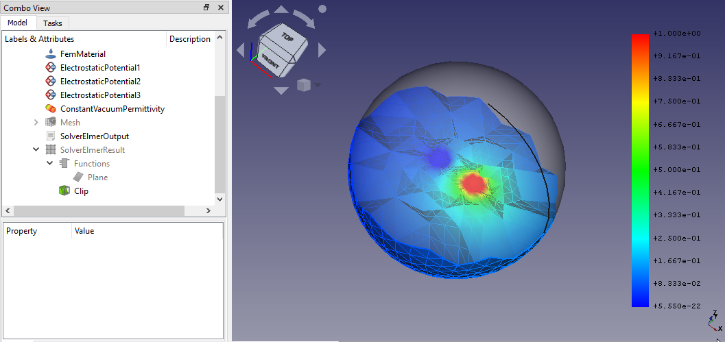
Das Endergebnis dieses Tutorium
Voraussetzungen
- Eine kompatible Version von FreeCAD, die in der Tutorial-Übersicht angegeben ist.
- Den Befehl Hilfe → Über FreeCAD verwenden, um die installierte Version von FreeCAD anzuzeigen.
- Zum Laden des Beispiels, Anzeigen des Netzes und der Geometrie sowie zum Visualisieren der Ergebnisse ist keine externe Software erforderlich.
- Für die Lösung der Finite-Elemente-Analyse (FEA) muss die Löser-Software Elmer auf dem Computer installiert sein. Informationen zur Installation von Elmer findet man auf dieser Seite.
Das Beispiel vorbereiten
Arbeitsbereich FEM laden
- FreeCAD starten, Der Arbeitsbereich Start sollte geladen werden.
- Zum Arbeitsbereich
FEM wechseln.
Das Beispiel laden
- Zu Werkzeuge →
FEM-Beispiele öffnen gehen.
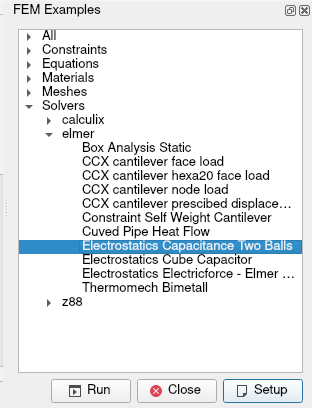
- Wenn sich die Grafische Benutzeroberfläche öffnet, sucht man "Elektrostatik Kapazität Zwei Kugeln" und öffnet es. Das Beispiel findet man ganz einfach unter Alle oder unter Löser → Elmer. Um das Beispiel zu öffnen, entweder darauf doppelklicken oder es auswählen und auf Einrichtung klicken.
Den Simulationsfall verstehen
Dieser Fall stellt die Lösung der Kapazität von perfekt leitenden Kugeln im freien Raum dar. Eine Spannungsdifferenz zwischen den Kugeln führt dazu, dass elektrische Ladung in das System eingebracht wird. Die Kugeln haben auch eine Eigenkapazität, die aus der Spannungsdifferenz mit dem Fernfeld resultiert. Daher muss eine symmetrische Kapazitätsmatrix der Größe 2 × 2 gelöst werden. Die Kapazitäten können aus zwei verschiedenen Spannungskonfigurationen berechnet werden.
Das Modell verstehen
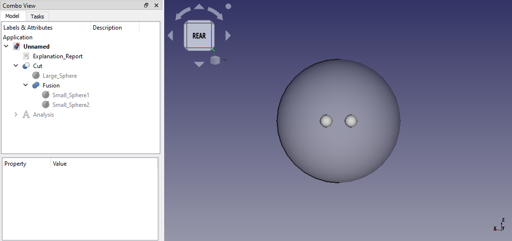
- Das Modell enthält drei Kugeln.
- Die beiden kleineren sind perfekt leitende Kugeln.
- Die größere Kugel simuliert die Umgebungsluft.
- Die beiden kleineren Kugeln werden miteinander verschmolzen und diese Verschmelzung wird dann von der größeren Kugel abgeschnitten.
Das Ausgangsmodell
Der Analyse-Container und seine Objekte
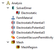
Die in dieser elektrostatischen Analyse verwendeten Objekte:
Analysecontainer
LöserElmer
Elektrostatik, die elektrostatische Gleichung
FemMaterial, ein flüssiges Material zur Darstellung der umfließenden Luft
Elektrostatisches Potential, Einschränkungen (3 davon)
Konstante Vakuumpermittivität, optional
Netz, ein Gmsh-Netz
MeshRegion, ein Netzbereich für die kleineren Kugeln
Die Objekte, wie sie in der Baumansicht dargestellt werden
Die FEA durchführen
- In der Baumansicht auf das Löser-Objekt
doppelklicken.
- Im gleichen Aufgaben-Fenster auf die Schaltfläche Schreiben klicken. Man beobachte das Protokollfenster, bis "write completed" angezeigt wird. Die möglicherweise angezeigte Warnung zur Vakuumpermittivität kann ignoriert werden.
- Auf die Schaltfläche Ausführen drücken. Da es sich um eine kleine Analyse handelt, sollte die Ausführung nur wenige Sekunden dauern. Bitte warten, bis Folgendes in der Ausgabe zu sehen ist: "ELMER SOLVER FINISHED AT".
- Auf die Schaltfläche Schliessen im Aufgaben-Fenster drücken, nachdem der Durchlauf beendet ist.
- In der Baumansicht sollten zwei neue Ergebnisobjekte erstellt werden,
SolverElmerResult und
SolverElmerOutput.
Wenn man beim Auslösen der Analyse eine Fehlermeldung zu Solver-Binärdateien oder Ähnlichem erhält, Folgendes überprüfen: Die Installation von Elmer.
Ergebnisse darstellen
- Sicherstellen, dass das Netz unsichtbar ist. Ist dies nicht der Fall, wählt man das
Netzobjekt aus und drückt Leertaste, um die Sichtbarkeit umzuschalten.
- Außerdem sicherstellen, dass das Schnitt-Objekt unsichtbar ist.
- Doppelklicken auf das
SolverElmerResult-Objekt, um dessen Aufgabendialog zu öffnen.
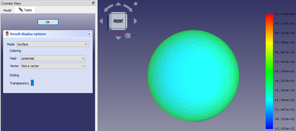
- Das "Feld" in "Potential" ändern und OK drücken.
- Man wird feststellen, dass sich die Farbe der Kugel zu Blau geändert hat und dass der Gradient auf der rechten Seite Werte von 0 bis 1 anzeigt. Es sollte in etwa so aussehen:
Die Ergebnisse nachbearbeiten
- Wir haben zwar das potenzielle Ergebnis erfolgreich visualisiert, sehen derzeit jedoch nur das Nullpotenzial in der Luft um die beiden Kugeln herum. Um das Potenzial auf den Kugeln anzuzeigen, müssen wir einen Zuschnitt-Filter anwenden.
- In der Baumansicht das Objekt
SolverElmerResult auswählen und dann in der Symbolleiste auf die Schaltfläche
Region Clip Filter klicken.
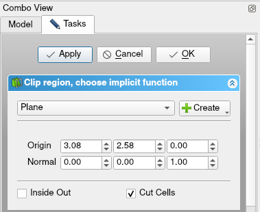
- Daraufhin öffnet sich ein Dialogfeld mit den Filterkonfigurationen. Dort auf die Schaltfläche
Create klicken und
-Ebene wählen. Dadurch wird eine Ebene durch den Mittelpunkt der Kugel hinzugefügt, an der das Ergebnisgitter geschnitten wird. Um die Schnittfläche zu glätten, aktiviert man die Option Cut Cells. Abschließend auf Anwenden klicken.
- In der Baumansicht gibt es einen neuen Eintrag namens Funktionen. Er enthält die erstellte
Ebene. Mit der Leertaste unsichtbar machen.
- Doppel-Klick auf das
Zuschnitt-Objekt in der Baumansicht.
- Das "Feld" auf "Potential" ändern und OK drücken.
- Die Sichtbarkeit des
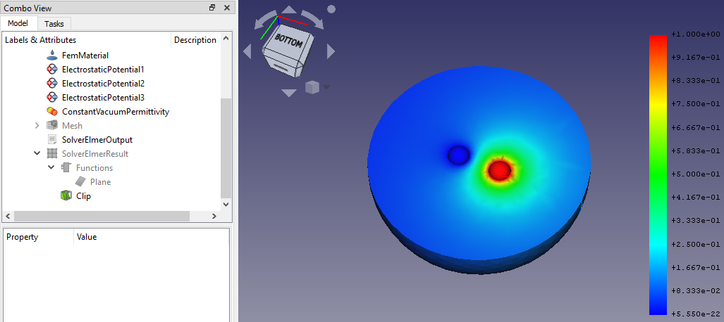
SolverElmerResult-Objekts mittels der Leertaste umschalten und man sieht etwa Folgendes:
Jetzt können wir diese potenzielle Verteilung in und um die Kugeln herum deutlich erkennen.
Beachte, dass wenn Änderungen anwenden aktiviert ist, das „Feld“ direkt im Zuschneiden-Dialogfeld ausgewählt werden konnte und somit hätte es nach der Erstellung der Ebene nicht erneut geöffnet werden müssen.
Die Kapazität ermitteln
- Unser eigentlicher Fokus liegt darauf, die Kapazität zu ermitteln, die in der
SolverElmerOutput enthalten sind.
- Doppelt auf
SolverElmerOutput klicken, um es zu öffnen. Nach unten scrollen, bis Folgendes zu finden ist:
StatElecSolve: Capacitance matrix computation performed (i,j,C_ij)
StatElecSolve:   1  1    5.07016E+00
StatElecSolve:   1  2    1.69328E+00
StatElecSolve:   2  2    5.07201E+00
- Hier ist unser gewünschtes Ergebnis
C12 = 1,69328. Dieser Wert liegt nahe an dem in den Elmer GUI Tutorials angegebenen Wert1,691. Wir können einen noch genaueren Wert erhalten, indem wir einen feineren NetzBereich erstellen, aber diese Aufgabe bleibt dem Benutzer überlassen. Außerdem wird dem Benutzer empfohlen, mit dem Schnittbereich-Filter zu experimentieren, um ein visuelles Ergebnis zu erhalten, das dem ersten Bild dieses Tutorials ähnelt.
- Materials: Solid Material, Fluid Material, Non-Linear Mechanical Material, Reinforced Material (Concrete); Material Editor
- Element Geometry: Beam Cross Section, Beam Rotation, Shell Plate Thickness, Fluid Section for 1D Flow
- Electromagnetic Boundary Conditions: Electrostatic Potential Boundary Condition, Current Density Boundary Condition, Magnetization Boundary Condition, Electric Charge Density
- Fluid Boundary Conditions: Initial Flow Velocity Condition, Initial Pressure Condition, Flow Velocity Boundary Condition
- Geometrical Analysis Features: Plane Multi-Point Constraint, Section Print Feature, Local Coordinate System
- Mechanical Boundary Conditions and Loads: Fixed Boundary Condition, Rigid Body Constraint, Displacement Boundary Condition, Contact Constraint, Tie Constraint, Spring Boundary Condition, Force Load, Pressure Load, Centrifugal Load, Gravity Load
- Thermal Boundary Conditions and Loads: Initial Temperature, Heat Flux Load, Temperature Boundary Condition, Body Heat Source
- Overwrite Constants: Constant Vacuum Permittivity
- Mesh: Mesh From Shape by Netgen, Mesh From Shape by Gmsh, Mesh Boundary Layer, Mesh Refinement, Mesh Group, Erase Elements, FEM Mesh to Mesh
- Solve: Solver CalculiX, Solver Elmer, Solver Mystran, Solver Z88; Mechanical Equations: Elasticity Equation, Deformation Equation; Electromagnetic Equations: Electrostatic Equation, Electricforce Equation, Magnetodynamic Equation, Magnetodynamic 2D Equation, Static Current Equation; Flow Equation, Flux Equation, Heat Equation, Solver Job Control, Run Solver
- Results: Purge Results, Show Result, Apply Changes to Pipeline, Post Pipeline From Result, Pipeline Branch, Warp Filter, Scalar Clip Filter, Function Cut Filter, Region Clip Filter, Contours Filter, Glyph Filter, Line Clip Filter, Stress Linearization Plot, Data at Point Clip Filter, Calculator Filter; Filter Functions: Plane, Sphere, Cylinder, Box; Data Visualizations: Create Lineplot, Create Histogram, Create Table
- Utilities: Clipping Plane on Face, Remove All Clipping Planes, FEM Examples; Clear FEM Mesh, Display Mesh Info
- Additional: Preferences; FEM Install, FEM Mesh, FEM Solver, FEM CalculiX, FEM Concrete; FEM Element Types
- Erste Schritte
- Installation: Herunterladen, Windows, Linux, Mac, Zusätzliche Komponenten, Docker, AppImage, Ubuntu Snap
- Grundlagen: Über FreeCAD, Graphische Oberfläche, Mausbedienung, Auswahlmethoden, Objektname, Voreinstellungseditor, Arbeitsbereiche, Dokumentstruktur, Objekteigenschaften, FreeCAD unterstützen, Spenden
- Hilfe: Anleitungen, Videoanleitungen
- Arbeitsbereiche: Std Base, Arch, Assembly, BIM, CAM, Draft, FEM, Inspection, Material, Mesh, OpenSCAD, Part, PartDesign, Points, Reverse Engineering, Robot, Sketcher, Spreadsheet, Surface, TechDraw, Test Framework
