Macro Half-Hull Model/de
|
|
| Beschreibung |
|---|
| Dieses Makro erzeugt sowohl dreidimensionale Halb- als auch Vollrumpfmodelle aus einer Reihe von 2D-Linienzeichnungen. Dieses Makro erstellt einfache Modelle der Rümpfe von Booten und Schiffen. Es soll Menschen helfen, die Rümpfe modellieren oder entwerfen, indem es die Oberfläche des Rumpfes in einer einfachen und zeitnahen Weise bereitstellt, so dass sie den zeitaufwendigen vollständigen Prozess vermeiden können. Versionsmakro : 1.0 Datum der letzten Änderung : 2016-01-25 FreeCAD version : <= 0.16 Herunterladen : Werkzeugleisten-Symbol Autor: Piffpoof |
| Autor |
| Piffpoof |
| Herunterladen |
| Werkzeugleisten-Symbol |
| Links |
| Makros Rezepte Wie man Makros installiert Symbolleisten anpassen |
| Macro-Version |
| 1.0 |
| Datum der letzten Änderung |
| 2016-01-25 |
| FreeCAD-Version(s) |
| <= 0.16 |
| Standardverknüpfung |
| None |
| Siehe auch |
| None |
Beschreibung
Dieses Makro erstellt einfache Modelle der Rümpfe von Booten und Schiffen. Es soll Personen, die Rümpfe modellieren oder entwerfen, helfen, indem es die Oberfläche des Rumpfes auf einfache und zeitnahe Weise bereitstellt, so dass sie den zeitaufwändigen vollständigen Prozess vermeiden können.
Temporary code for external macro link. Do not use this code. This code is used exclusively by Addon Manager. Link for optional manual installation: Macro
# This code is copied instead of the original macro code
# to guide the user to the online download page.
# Use it if the code of the macro is larger than 64 KB and cannot be included in the wiki
# or if the RAW code URL is somewhere else in the wiki.

from PySide import QtGui, QtCore

diag = QtGui.QMessageBox(QtGui.QMessageBox.Information,
    "Information",
    "This macro must be downloaded from this link\n"
    "\n"
    "http://pastebin.com/raw/tZMpUi6F" + "\n"
    "\n"
    "Quit this window to access the download page")

diag.setWindowFlags(QtCore.Qt.WindowStaysOnTopHint)
diag.setWindowModality(QtCore.Qt.ApplicationModal)
diag.exec_()

import webbrowser
webbrowser.open("http://pastebin.com/raw/tZMpUi6F")

Hintergrund
Seit der Antike mussten Bootsbauer Boote entwerfen und sie dann in einer dreidimensionalen Umgebung realisieren, in der nur wenige Linien gerade, nur wenige Flächen eben und keine Winkel über eine Strecke konstant sind. Anhand von Rumpfmodellen wurden maßstabsgetreue Modelle angefertigt, die dann zur Überprüfung des Entwurfs oder zur Kommunikation von Konzepten mit anderen Personen verwendet werden konnten. Die Gesetze der Hydrodynamik verlangen, dass jedes Schiff, das sich durch eine Flüssigkeit bewegt, im Querschnitt symmetrisch sein muss, wenn es genau verfolgt werden soll (sich in einer geraden Linie bewegen soll). Folglich genügte es, eine Seite des Rumpfes im Modell zu bauen - wenn der halbe Rumpf perfekt war, dann würde auch sein Spiegelbild perfekt sein. In späteren Jahren wurden Halbrümpfe für symbolische Zwecke wie Plaketten und nautische Kunst verwendet.
Dieser Code entstand aus einem Projekt zur Erstellung eines Modells in FreeCAD von einem 12,5 Meter langen Segelboot. Die Erbauer hatten keine Zeichnungen mehr und der Sohn des ursprünglichen Besitzers bezweifelte, dass es jemals vollständige Zeichnungen gab. Folglich mussten die Rumpfabmessungen gemessen und dann ein Modell in der Software konstruiert werden. Moderne Softwarepakete wie FreeCAD bieten viele nützliche Funktionen wie Symmetriebeschränkungen, aber wenn das Endergebnis ein Modell sein soll, das „ins Auge sticht“, ist viel „Feinarbeit“ an den Modellen erforderlich. Dieser Code wurde geschrieben, um diesen Prozess zu automatisieren.
Der ursprüngliche Zweck dieses Codes war es, einen symmetrischen Rumpf bereitzustellen, der formbar war, damit er an das zu konstruierende 3D-Modell angepasst werden konnte. Im weiteren Verlauf wurde das Programm verallgemeinert, so dass es hoffentlich für Personen von Nutzen sein wird:
- Bootskonstrukteure, die Bootspläne erstellen, aus denen gebaut werden kann
- Bootsbauer, die versuchen, das zu modellieren, was auf ihren Plänen beschrieben ist
- Modellrumpfbauer.
Natürlich verfügen kommerzielle Bootsdesigner über alle Arten von High-End-Software, die sie bei ihrer Arbeit unterstützt. Dieses Programm soll diese nicht ersetzen. Vielmehr ist es für Hobbybastler oder Selbstbauer gedacht, die gerne herumtüfteln.
Nautische Blaupausen haben eine eigene Geschichte in Bezug auf Bauten und sind daher etwas anders in der Darstellung. Dies ist ein Beispiel für ein Segelboot, das mehr als ein Jahrhundert alt ist:

Eines der Endziele dieses Programms ist es, mit der Entwurf Arbeitsbereich einige dieser Pläne zu generieren, indem das Modell zur Erzeugung der Linien verwendet wird.
Hinweis zu Einheiten in FreeCAD:
Zur Zeit gibt es kein wirkliches Einheiten-Verwaltungssystem in FreeCAD, aber natürlich braucht ein Bootsbauer oder Modellbauer ein genaues Maßsystem. Um dieses Makro zu verwenden, entscheidet man sich, die FreeCAD-Rastergröße auf das einzustellen, was immer für die Arbeit angemessen ist (z. B. mm, cm, Zoll, Fuß). FreeCAD ist konsistent, eine FreeCAD-Einheit wird immer gleich einer FreeCAD-Einheit sein. Und wenn man sich entschieden hat, dass eine FreeCAD-Einheit einer bestimmten physikalischen Länge entspricht, dann werden die Zeichnungen konsistent bemaßt bleiben. Zur Zeit wird an einem Einheitensystem für FreeCAD gearbeitet, so dass sich diese Situation bald ändern könnte.
Beschreibung
Für dieses Makro werden die Rumpfformen durch ein Minimum von drei FreeCAD-Skizzen definiert: eine in der YZ-Ebene, eine oder mehrere in der XZ-Ebene, eine in der XY-Ebene. Hier ist der minimale Rumpf, der von diesem Makro unterstützt wird, er hat nur drei Skizzen:

Anmerkung: In der obigen Abbildung schauen wir direkt auf das Heck, der Bug zeigt vom Standpunkt weg.
Von vorne nach hinten (vom Bug zum Heck) sind die drei Skizzen:
| Steven |
YZ-Ebene |
rote Linie in der Skizze |
| Querspante |
XZ-Ebene |
grüne Linie in der Skizze |
| Querbalken |
XY-Ebene |
blaue Linie in der Skizze |
Vielleicht ist es mit sieben Skizzen (eine in der YZ-Ebene, eine in der XY-Ebene und fünf in der XZ-Ebene) einfacher zu sehen:

Mit fünf Skizzen in der XZ-Ebene wird es immer einfacher, die Form des Rumpfes zu erkennen. Die nächsten zwei Bilder zeigen die Skizzenlinien, die dem von FreeCAD konstruierten Modell überlagert sind,

das zweite ist das gleiche Modell um 90 Grad gedreht, so dass der Bug im Vordergrund ist:

Einige Punkte, die zu beachten sind:
- Die Skizzen gelten nur für:
- den Steven (oder Buglinie) in der YZ-Ebene (rot in der obigen Abbildung);
- die Oberseite des Heckspiegels in der XY-Ebene (blau in der obigen Abbildung);
- mehrere Querschnitte des Rumpfes in der XZ-Ebene (grün in der obigen Abbildung)
- In den Skizzen wird nur die Steuerbordseite des Rumpfes gezeichnet, die Backbordseite wird als Spiegelbild erzeugt.
- Jede Linie mit mehreren Segmenten muss in einer separaten Skizze enthalten sein.
- Jede Skizze muss die gleiche Anzahl von Liniensegmenten haben (in den vorherigen Beispielen sind es drei).
- Je mehr Liniensegmente in jeder Skizze enthalten sind, desto genauer entspricht das von FreeCAD generierte Modell einem gekrümmten Rumpf.
- Die Anzahl der Liniensegmente in jeder Skizze ist unbegrenzt, es kann eine beliebige Anzahl ab eins sein.
- Die Anzahl der Skizzen in der XZ-Ebene (d. h. Querschnitte) ist unbegrenzt, es kann eine beliebige Anzahl ab eins sein.
Mit genügend Skizzen kann sich das generierte Modell sogar annähern an:

Das HalbRumpf-Makro erzeugt vier Modelle:
- Steuerbord-Halbrumpf
- Backbord-Halbrumpf
- Kompletter Rumpf
- Schotten für den kompletten Rumpf, entweder mit einem Glattdeck oder mit einem Kajütdeck
Diese Modelle werden alle im einheitlichen Ortsraum von FreeCAD ausgegeben, sodass sie zusammengefügt werden können, beispielsweise können die Schotten nahtlos in den kompletten Rumpf eingefügt werden. Dies ist ein Bild von Schotten in einem Bootsmodell während des Baus:

Sowie die durch das Makro erzeugten Schotten (es muss beachtet werden, dass diese Schotten für ein Kajütdeck und nicht für ein Glattdeck bestimmt sind):

Das folgende zusammengesetzte Bild zeigt die wichtigsten Ergebnisse dieses Programms (die Backbord-Halbschale ist nicht abgebildet, entspricht jedoch der Steuerbord-Halbschale, die abgebildet ist). Die Ergebnisse sind im Uhrzeigersinn von der oberen linken Ecke aus angeordnet:
- Steuerbord-Halbschale
- Kompletter Rumpf
- Schotten (für ein Glattdeck, die Schotten im vorherigen Bild waren für ein Kajütdeck vorgesehen)
- der komplette Rumpf mit eingefügten Schotten

Als neue Funktionen kann das Makro optional auch Tafeln für die Halbschalen und sogar eine Flasche für den kompletten Rumpf erstellen:


Installation
Der gesamte Code für halfHullModel.FCMacro befindet sich in einem Makro. Die Installation besteht also darin, den Code in das entsprechende Makroverzeichnis zu kopieren und das Build-Dienstprogramm über das Makro-Menü, die Python-Konsole oder eine Symbolleisten-Schaltfläche (die bevorzugte Methode) aufzurufen.
- siehe Wie man Makros installiert Informationen zur Installation dieses Makro-Codes
- siehe Symbolleisten anpassen für Informationen zur Installation als Schaltfläche in einer Symbolleiste
Anwendung
Die FreeCAD-Operationen, die bei der Erstellung des Rumpfmodells zum Einsatz kommen, sind ziemlich komplex und zahlreich. Dinge wie die Richtung, in der eine Linie gezeichnet wird, können dazu führen, dass die FreeCAD-Konstruktion des Rumpfes entweder abgebrochen wird oder wie folgt aussieht:

Daher müssen die folgenden Schritte genau befolgt werden. Das Makro lässt zwar gewisse Dateninkonsistenzen zu, aber im Allgemeinen sieht das Ergebnis bei falschen Daten (d. h. den Skizzen) wie eine Käsereibe aus oder das Makro schlägt mit einer Fehlermeldung fehl.
Die folgenden Anweisungen beziehen sich auf die Quadranten des XY-Diagramms, d. h. auf die vier Viertel des XY-Diagramms, die wie folgt bezeichnet sind:

Ein neues Dokument erzeugen
Als Erstes erstellt man ein neues Dokument in FreeCAD ![]() . Dieses Dokument enthält alle Skizzen, aus denen sich die Rumpfdefinition zusammensetzt.
. Dieses Dokument enthält alle Skizzen, aus denen sich die Rumpfdefinition zusammensetzt.
Den Kiel erstellen
Der erste Schritt besteht darin, Daten für das zu erstellende Rumpfmodell zu erstellen. Die Daten werden in Form von Skizzen innerhalb von FreeCAD bereitgestellt. Nachdem das Rumpfmodell erstellt wurde, können Änderungen einfach durch Bearbeiten der Skizzen vorgenommen werden. Der zweite Schritt besteht darin, das Makro wiederholt auszuführen.
- Eine neue Skizze
 , in der YZ-Ebene erstellen
 - Am Ursprung (0,0) beginnen und nach oben in den Quadranten I zeichnen.
- Das untere Ende des Kiels befindet sich am Ursprung (0,0). Dies ist der Punkt, von dem aus die Platzierung aller Querschnitte und des Heckspiegel erfolgt.
- Die Anzahl der Liniensegmente in dieser Skizze bestimmt die Anzahl, die in jeder anderen Skizze erforderlich ist.
- Skizze speichern

- Zur leichteren Identifizierung empfiehlt es sich, die Skizze beispielsweise als „Kiel-Skizze” zu benennen.

Die Querschnittsskizzen erstellen
- Eine neue Skizze auf der XZ-Ebene erstellen.
- Der folgende Dialog wird angezeigt:
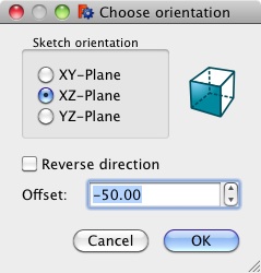
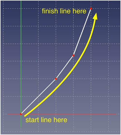
Der Dialog fragt, wie weit vom Ursprung die Skizze platziert werden soll. Dies bezieht sich darauf, wie weit der Querschnitt vom unteren Ende der Stammlinie (die bei (0,0) platziert wurde) entfernt ist. Die Querschnitte können gleichmäßig verteilt sein, müssen es aber nicht. Der vorderste Querschnitt befindet sich bei Y=0 (d. h. am Ursprung, wo die Unterseite der Stammlinie endet) oder bei Y<=0. Die Querschnitte befinden sich bei zunehmend negativen Y-Werten, bis der Spiegel den negativsten Y-Wert erreicht. Im obigen Beispiel wird die Querschnittsskizze 50 FreeCAD-Einheiten vom Ursprung entfernt auf der negativen Y-Achse platziert. - Beginnen Sie auf der Y-Achse und zeichnen Sie nach oben in Quadrant I. Der erste (d. h. vorderste) Querschnitt sollte am Ursprung (0,0) beginnen (sonst sieht es seltsam aus, da die Stammlinie bei 0,0 endet), aber andere Querschnitte müssen nur auf der Y-Achse beginnen.
- Verwenden Sie dieselbe Anzahl von Liniensegmenten wie in der Stammlinienzeichnung.
- Skizze speichern
- Diesen Schritt nach Bedarf wiederholen. Es kann schneller sein, diese Skizze zu kopieren und die Kopien dann auf der Y-Achse zu verteilen. Bei Bedarf können Änderungen an den einzelnen Skizzen vorgenommen werden.
- Für die Benennung ist es einfacher, den Querschnitten eine Art Reihenfolge zu geben, beginnend am Bug (d. h. der Buglinie) und steigend in Richtung Heck (d. h. dem Heckspiegel).

Die Heckspiegel-Skizze in der XY-Ebene erstellen
- Neue Skizze auf der XY-Ebene erzeugen
- Auf der Y-Achse zwischen Quadrant III und IV beginnen und nach oben in Quadrant IV zeichnen, sodass der Endpunkt mit dem Punkt ganz rechts des untersten Querschnitts in der YZ-Ebene übereinstimmt.
- Dieselbe Anzahl von Liniensegmenten wie in der Stammlinie-Skizze verwenden.
- Die Skizze speichern
- Zur leichteren Identifizierung empfiehlt es sich, die Skizze beispielsweise als „transom sketch” zu benennen.

Das neue Dokument speichern
Nun kann das Dokument ![]() , das die Skizzen enthält, die die Rumpfform definieren, gespeichert werden. Dazu vergibt man einen aussagekräftigen Namen.
, das die Skizzen enthält, die die Rumpfform definieren, gespeichert werden. Dazu vergibt man einen aussagekräftigen Namen.
Nachdem alle Skizzen erstellt und positioniert wurden, sollte das Dokument von oben betrachtet wie folgt aussehen ![]() :
:

Die wichtigsten Einschränkungen für die Erstellung des Modells sind:
- Der untere Rand des Kiels sollte bei (0,0) enden.
- Das untere mittlere Ende jedes Querschnitts sollte an der Y-Achse enden – es muss beachtet werden, dass es einen beliebigen Z-Wert haben kann.
Damit ist der erste Schritt abgeschlossen, bei dem die Daten erstellt werden, die das Makro zum Erstellen von Halbschalen und vollständigen Schalen verwendet. Der zweite Schritt wird im folgenden Abschnitt mit dem Titel Benutzeroberfläche beschrieben.
Benutzeroberfläche
In diesem Schritt sammelt das Makro einige Informationen vom Benutzer und verarbeitet dann die eingegebenen Skizzen, um die gewünschten Rumpfmodelle zu generieren. Dies ist das einzige GUI-Bild für das Makro und enthält in erster Linie Konfigurationsdetails für die Erstellung der Rumpfmodelle aus den Skizzen:

Die Auswahlmöglichkeiten im GUI-Fenster sind:
- Starboard half-hull: Wenn diese Option aktiviert wird, erzeugt das Makro ein Modell der Steuerbord-Halbschale.
- Mounting plaque: Wenn diese Option aktiviert ist, montiert das Makro den Halbrumpf auf einer Platte.
- Allow space for keel: Wenn diese Option aktiviert ist, wird der halbe Rumpf höher auf der Platte montiert als in der Mitte, damit ein separat erstellter Kiel unterhalb des Rumpfes platziert werden kann.
- Port half-hull: Wenn diese Option aktiviert ist, erzeugt das Makro ein Port-Halbschalenmodell.
- Mounting plaque: Wenn diese Option aktiviert ist, montiert das Makro den Halbrumpf auf einer Platte.
- Allow space for keel: Wenn diese Option aktiviert ist, wird der halbe Rumpf höher auf der Platte montiert als in der Mitte, damit ein separat erstellter Kiel unterhalb des Rumpfes platziert werden kann.
- Complete hull: Wenn diese Option aktiviert ist, erstellt das Makro ein vollständiges Modell.
- Bottle for complete hull: Wenn diese Option aktiviert ist, platziert das Makro den gesamten Rumpf in einer transparenten Flasche (komplett mit Korken).
- Allow space for keel: Wenn diese Option aktiviert ist, wird der halbe Rumpf höher in der Flasche positioniert als in der Mitte, damit ein separat erstellter Kiel unterhalb des Rumpfes platziert werden kann.
- Bulkheads for flush deck: Wenn diese Option aktiviert ist, erzeugt das Makro Schotten, deren Oberkante mit der Oberkante des Rumpfes bündig ist. Für die beiden vordersten Querschnitte und die beiden hintersten Querschnitte werden keine Schotten erzeugt.
- Bulkheads for coachhouse: Wenn diese Option aktiviert ist, erzeugt das Makro Schotten, deren Oberkante möglicherweise über der Oberkante des Rumpfes liegt.
- Die zu überspringenden Schotten am Bug bestimmen, wie viele Querschnitte ohne Schott am Bug verbleiben.
- Die Anzahl der zu überspringenden Schotten am Heck bestimmt, wie viele Querschnitte ohne Schott am Heck verbleiben.
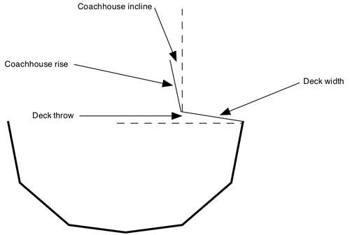
- Die Abmessungen der Oberseite der Schotten werden gemäß der folgenden Abbildung konfiguriert:
- Schaltfläche Cancel (Abbrechen): Die Ausführung wird angehalten und das Fenster geschlossen.
- Schaltfläche Re-Use Last File (Letzte Datei wiederverwenden): Die Ausführung verwendet die Datendatei UND EINSTELLUNGEN aus dem letzten Durchlauf, alle Änderungen an den Einstellungen werden ignoriert.
- Schaltfläche Select File (Datei auswählen): Das Standardfenster Datei öffnen wird geöffnet, in dem der Benutzer entweder eine Datei auswählen oder auf Abbrechen klicken und das Fenster schließen kann.

Wenn das Makro ausgeführt wird, nimmt es Konfigurationsdaten vom Benutzer entgegen und liest dann Sketcher-Skizzen in der ausgewählten Eingabedatei.
Hinweis: Während das Makro die Skizzen durchläuft, druckt es alle Ausnahmen sowie einige Meilensteine in der Berichtsansicht aus. Wenn man unerwartete Ergebnisse erhält oder Teile fehlen, sollte man wahrscheinlich zuerst hier nachsehen.
Optionen
Es gibt verschiedene Arten von Bug- und Heckformen für Boote, wobei die Heckformen eine viel größere Vielfalt aufweisen als die Bugformen. Hier sind Beispiele für Heckspiegel und Bugformen aus der realen Welt neben den entsprechenden Makro-Ausgaben:
Deckssprung-Heck
Wahrscheinlich der häufigste Hecktyp, typisch für alle Schiffsgrößen, von Handelsschiffen bis hin zu Ruderbooten.
 |
 |
- Der XY-Heckspiegel sollte so nah wie möglich am hintersten Querschnitt liegen.
Zuckerschaufel-Heck
Am ehesten auf einer Segelyacht zu finden, ist es ein Produkt des Designs zur Maximierung der Wasserlinienlänge, um von den Klassenregeln für Segelregatten zu profitieren.
 |
 |
- Die beiden hintersten Querschnitte so nah wie möglich aneinanderlegen, dann den hintersten der beiden um einen Winkel von 45 Grad (oder wie erforderlich) um die X-Achse drehen.
Kanu-Heck
Zu finden auf allen Arten von Wasserfahrzeugen, Motor- und Segelbooten, Freizeit- und Handelsbooten.
 |
 |
- Die beiden hintersten Querschnitte so nah wie möglich aneinanderlegen, dann den hintersten der beiden um 45 Grad um die X-Achse drehen.
Normaler Bogen
Bei den Bugformen gibt es viel weniger Vielfalt als bei den Heckspiegeln:
 |
 |
Trireme-Bug
Obwohl es in den letzten 2000 Jahren nicht mehr sehr häufig anzutreffen war, war dies einst das definitive Bugprofil für Kriegsschiffe:
 |
 |
- Damit der Bug korrekt ist, muss die Polylinie für den Steven von unten nach oben gezeichnet werden, was im Sketcher von rechts nach links bedeutet.
Beispieldateien
Diese Dateien sind Beispiele für Skizzen-Daten, die mit dem Makro verwendet werden können. Es handelt sich dabei hauptsächlich um die Modelle für die Bildschirmaufnahmen im Abschnitt Optionen oben. Die Dateien funktionieren mit dem Makro und können daher heruntergeladen und an die spezifischen Anforderungen angepasst werden. Das Präfix 5x3 (zum Beispiel) bedeutet, dass das Modell 5 Querschnitte und 3 Liniensegmente pro Querschnitt (d. h. Skizze) hat.
Um eine der Beispieldateien zu verwenden, mit der rechten Maustaste auf den Dateilink klicken und im Menü Datei speichern unter... wählen. Der Dateiname wird angegeben. Den gewünschten Ordner/das gewünschte Verzeichnis wählen, in dem die Beispieldatei gespeichert werden soll.
- 3x1 Hülle mit der minimalen Anzahl von Skizzen (Stammlinie, ein Querschnitt, Querbalken) mit 1 Liniensegment pro Skizze <<<<< FUNKTIONIERT DERZEIT NICHT
- 5x3 mit normalem Bug
- 5x3 mit Trireme-Bug
- 5x3 mit Kanuheck
- 5x3 mit durchsichtigem Heckspiegel
- 5x3 mit Zuckerschaufel Heck
- 5x5 Arbeitsschiff
- 7x5 Piratenschiff
- 12x3 Segelyacht
Anmerkungen
- Fast alle Beispiele auf dieser Seite wurden mit nur drei Liniensegmenten erstellt, die die Seite des Rumpfes definieren, was zu einem sehr facettierten Erscheinungsbild führt. Eine Erhöhung der Anzahl der Segmente in jeder Skizze würde eine viel glattere Oberfläche erzeugen, was den Realismus erhöhen würde.
- Es werden keine Kiele, Skegs oder Ruder erstellt, d. h. es werden keine Teile des nassen Bereichs erstellt.
- Es werden keine quadratischen Bugspitzen wie bei Schubbooten oder Schleppkähnen erstellt.
- Es werden keine U-Boote erstellt (allerdings wird die untere Hälfte eines U-Boots erstellt).
Bekannte Probleme
Die Funktion „Ruled Surface“ (Regelfläche) von FreeCAD wird verwendet, um die Rumpfabschnitte aus den Skizzen zu generieren. Manchmal kann es vorkommen, dass sie ein falsches Ergebnis liefert und statt einer glatten, ebenen Fläche eine geriffelte Oberfläche anzeigt. Dies tritt in der Regel auf, wenn die Skizzen gedreht werden, beispielsweise beim Modellieren eines Sugar-Scoop-Hecks. Auch das Abwinkeln eines Sheer-Transom-Hecks kann dies verursachen. Wenn dies auftritt, dann in der Regel entweder bei den Halbschalenmodellen oder beim kompletten Rumpfmodell – es scheint nie bei allen drei Modellen desselben Rumpfes aufzutreten. Außerdem tritt es in der Regel nur am äußersten Bug oder Heck auf. Wenn es in der Mitte des Bootes auftritt, wurde höchstwahrscheinlich eine der Skizzen in die falsche Richtung gezeichnet (d. h. entweder in zufälliger Reihenfolge oder von oben nach unten, während alle Linien von unten nach oben gezeichnet werden sollten).
Es kann in der Regel mit den folgenden Schritten entfernt werden:
- In der Registerkarte Modell der Combo-Ansicht auf das fehlerhafte Segment klicken, um es auszuwählen. Das fehlerhafte Segment wird dann in der Anzeige hervorgehoben angezeigt.
- Die Registerkarte Daten in der unteren Hälfte der Combo-Ansicht auswählen. Im unteren Teil des Fensters befindet sich die Bezeichnung „Regelfläche“ mit einem einzigen Parameter „Ausrichtung“.
- Rechts davon befindet sich ein Popup-Menü mit den Werten „Automatisch“, „Vorwärts“ und „Umgekehrt“. Es ist zunächst auf „Automatisch“ eingestellt.
- Eine der anderen Einstellungen ausprobieren (daran denken, dass das fehlerhafte Segment weiterhin im oberen Teil der Combo-Ansicht ausgewählt sein muss). In der Regel wird das Problem dadurch behoben.
Die folgende Bildschirmaufnahme zeigt den relevanten Teil des Bildschirms:

Zukünftige Möglichkeiten
- Ersetzen von Liniensegmenten von Querschnitten durch gekrümmte Linien: Dies befindet sich noch in der Ideenphase, würde jedoch zu einer wesentlich glatteren Oberfläche in vertikaler Richtung führen, während die horizontale Oberfläche weiterhin facettiert bliebe, wie es derzeit der Fall ist.
- Integration mit dem Arbeitsbereich Draft, um Zeichnungen aus Modellen zu erstellen: ein erstes Ziel, dessen Machbarkeit jedoch noch nicht untersucht wurde
- Umgang mit Kielen, Skegs und Rudern: Eine Möglichkeit, Kiele mit dem derzeitigen System zu modellieren, besteht darin, den Kiel als eigenständigen Halbrumpf zu modellieren und ihn dann am Boden des Hauptrumpfs anzubringen; für Ruder und Skegs würde dies jedoch nichts ändern.
Glossar
Wie bei jedem alten und praktizierten Handwerk hat sich auch im Zusammenhang mit Schiffen, Booten und nautischen Praktiken ein reichhaltiges und manchmal verwirrendes Vokabular entwickelt. Bei der Beschreibung dieses Makros ist es sowohl umständlich als auch ineffizient, den Prozess ohne die Verwendung der korrekten und genauen Begriffe zu beschreiben. Das offensichtliche Problem besteht darin, dass der durchschnittliche Laie mit solchen Begriffen nicht vertraut ist, daher dieses Vokabular:
| achtern | die Rückseite von irgendetwas auf einem Boot |
| chine | Eine ebene Fläche einer Hülle kann verwendet werden, um eine gekrümmte Oberfläche zu approximieren oder als fertige Bautechnik. |
| coachhouse - Kutscherhaus | Der Teil des Mitteldecks, der über das Deck hinausragt – in der Regel, um mehr Kopffreiheit im Inneren des Bootes zu schaffen. |
| flush deck | ein Deck, das sich nahtlos von einer Seite des Rumpfes zur anderen erstreckt, das Gegenteil eines Kajütdecks |
| bugwärts | Ebenso 'Bug'; die Vorderseite von allem auf einem Boot |
| Backbord | linke Seite nach vorne blickend |
| Steuerbord | rechte Seite nach vorne blickend |
| Stammlinie | die geneigte vertikale Kante, die den Bug eines Rumpfes bildet |
| Querbalken | die gekrümmte Oberkante der Heckfläche, die flach oder gekrümmt sein kann |
Verweise
- Half Hull Model Ship (Wikipedia)
- Why Half Hulls (Maritime Half Hull Ship Models and Nautical Art website)
- Traditional Model Yacht Design (US Vintage Model Yacht Group)
Skript
Werkzeugleisten-Symbol 
Macro_Half_Hull_Model.FCMacro
Dieses Skript läuft fehlerfrei. Aufgrund der Vielzahl möglicher Eingaben kann es jedoch bei einigen Eingaben zu Fehlern kommen. In diesem Wenn ja, meldet man dies bitte.
Das Skript ist zu lang, um es im Wiki anzuzeigen, daher muss es kopiert oder heruntergeladen werden von ungekürzte Skriptdatei auf pastebin.com