SheetMetal AddCutout
This documentation is not finished. Please help and contribute documentation.
GuiCommand model explains how commands should be documented. Browse Category:UnfinishedDocu to see more incomplete pages like this one. See Category:Command Reference for all commands.
See WikiPages to learn about editing the wiki pages, and go to Help FreeCAD to learn about other ways in which you can contribute.
|
|
| Menu location |
|---|
| SheetMetal → Extruded Cutout |
| Workbenches |
| SheetMetal |
| Default shortcut |
| E C |
| Introduced in version |
| 0.5.04 |
| See also |
| None |
Description
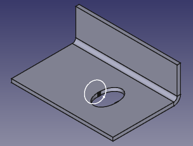
The SheetMetal AddCutout command creates an extruded cutout from a sketch extrusion.
The difference between a 'normal' cutout and an extruded cutout is that in the latter case the edges are made perpendicular to the selected face of the sheet metal object. The effect of the command is only visible if the sketch is not plane-parallel to the face.
Extruded cutout based on a circular sketch
Usage
- Select a planar face and a sketch with a closed contour (in any order).
- There are several ways to invoke the command:
- Press the
Extruded Cutout button.
- Select the SheetMetal →
Extruded Cutout option from the menu.
- Right-click in the Tree View or the 3D View and select the SheetMetal →
Extruded Cutout option from the context menu.
- Use the keyboard shortcut: E then C.
- Press the
- The Extruded Cutout properties Task Panel opens.
- Optionally press the Face button to reselect the planar face.
- Optionally press the Sketch button to reselect a sketch.
- Optionally adjust the parameters in the Task Panel.
- Press the OK button to finish the command and close the Task Panel.
- An ExtrudedCutout object will be created consisting of one or more holes in a line through the object.
- Optionally adjust the parameters in the Property View.
Properties
See also: Property View.
A SheetMetal ExtrudedCutout object is derived from a Part Feature object or, if it is inside a PartDesign Body, from a PartDesign Feature object, and inherits all its properties. It also has the following additional properties:
Data
Extruded Cutout
- DataCut Side (
Enumeration): Default isInside. Side of the cut. - DataCut Type (
Enumeration): Default isThrough everything both sides. Cut type. - Data (hidden)Extrusion Length1 (
Length): Default is500.0 mm. Length of the extrusion direction 1. - Data (hidden)Extrusion Length2 (
Length): Default is500.0 mm. Length of the extrusion direction 2. - DataSelected Face (
LinkSub): The selected object and face. - DataSketch (
Link): The sketch for the cut.
Extruded Cutout Improvements
- DataImprove Cut (
Bool): Default isFalse. Improve cut geometry if it enters the cutting zone. Only selectTrueif the cut needs fix, because it can be slow. - Data (hidden)Improve Level (
IntegerConstraint): Default is4. Level of cut improvement quality. More than 10 can take a very long time. - DataRefine (
Bool): Default isFalse. Refine the geometry.
