SheetMetal SketchOnSheet
This documentation is not finished. Please help and contribute documentation.
GuiCommand model explains how commands should be documented. Browse Category:UnfinishedDocu to see more incomplete pages like this one. See Category:Command Reference for all commands.
See WikiPages to learn about editing the wiki pages, and go to Help FreeCAD to learn about other ways in which you can contribute.
|
|
| Menu location |
|---|
| SheetMetal → Wrap Cutout |
| Workbenches |
| SheetMetal |
| Default shortcut |
| M S |
| Introduced in version |
| - |
| See also |
| None |
Description
The ![]() SheetMetal SketchOnSheet command cuts holes along the folded walls of a sheet metal object. For the hole layout a
SheetMetal SketchOnSheet command cuts holes along the folded walls of a sheet metal object. For the hole layout a ![]() sketch is used.
sketch is used.
In contrast to the ![]() PartDesign Pocket command, where holes are just cut along the sketch normal (local z axis), this tool acts as if it would unfold the sheet metal object, cut the holes, and refold the object.
PartDesign Pocket command, where holes are just cut along the sketch normal (local z axis), this tool acts as if it would unfold the sheet metal object, cut the holes, and refold the object.
Usage
- Select a planar face
- Add a coplanar
 sketch (i.e. lying on the same plane) for the hole layout to the selection (preferably from the Tree View).
 - There are several ways to invoke the command:
- Press the
 Wrap Cutout button.
 - Select the SheetMetal → Wrap Cutout option from the menu.
- Right-click in the Tree View or the 3D View and select the SheetMetal → Wrap Cutout option from the context menu.
- Use the keyboard shortcut: M then S.
- Press the
- A SketchOnSheet object will be created consisting of holes starting on the selected plane and following along the bends and walls.
- Optionally adjust the parameters in the Property View.
Notes
- The sketch may contain more than just one outline.
- Any outline has to touch the planar face, at least, otherwise it won't cut a hole at all.
Properties
See also: Property View.
A SheetMetal WrappedCutout object is derived from a Part Feature object or, if it is inside a PartDesign Body, from a PartDesign Feature object, and inherits all its properties. It also has the following additional properties:
Data
Parameters
- DataSketch (
Link): "Sketch on Sheetmetal". Link to the hole layout/cut-out sketch. - Database Object (
LinkSub): "Base Object". Link to the planar face where the cut-out starts. - Datakfactor (
FloatConstraint): "Gap from Left Side". Default:0,50.
Example

A simple thingamajig
Preparation
This thingamajig is made of a folded sheet metal object with holes added.
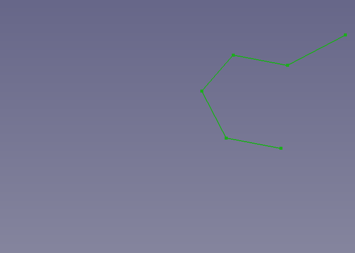
And so one open contour sketch for the sheet metal and one sketch for the hole layout have to be prepared in advance.
One straight line of the first sketch must be coplanar to the other sketch plane, this will result in coplanar sketch and face used in the next steps.

Just a contour and a hole layout
Workflow
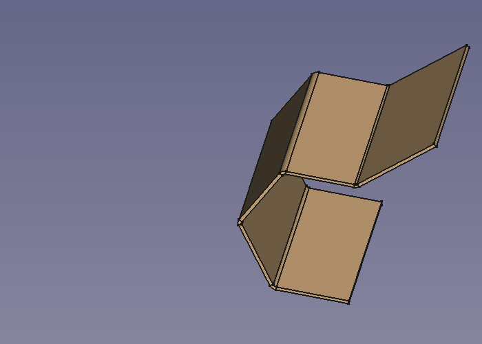
- Create a folded sheet metal object
- Select the contour sketch
- Press the
 Make Base Wall button
or use the keyboard shortcut: C then F
- Select the contour sketch
- Cut some holes
- Select the planar face
- Select the hole layout sketch

- Press the Sketch On Sheet metal button
or use the keyboard shortcut: M then S
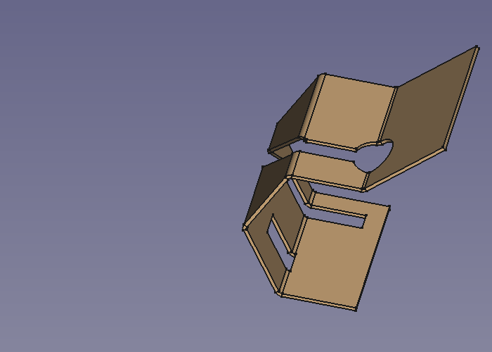
Done!
- Some hints
- Check if the folded object's thickness is built to the right side.
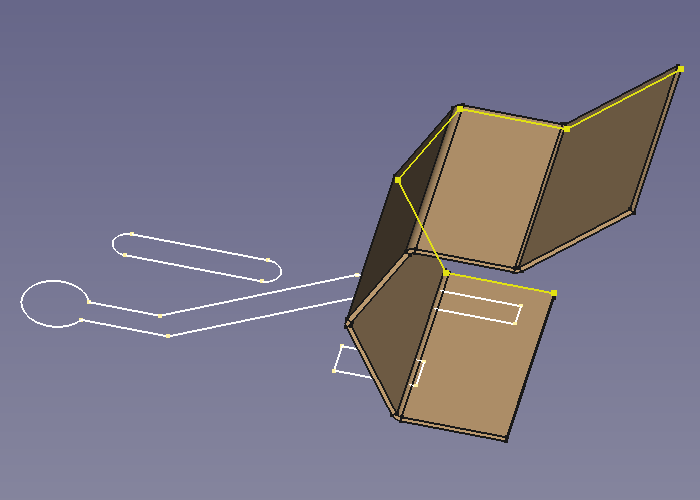
The yellow contour should lie on the top face of the bottom fold (as shown).
To reverse direction set the value of Bend Side property (Outside <-> Inside).
- Hole shapes not touching the used planar face won't cut holes into the folded object.
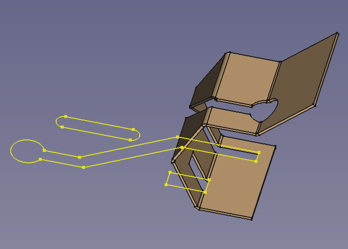
The lower rectangle which is hardly touching said face does cut a hole while the upper slot shape doesn't.
- Check if the folded object's thickness is built to the right side.


