SheetMetal AddBend
This documentation is not finished. Please help and contribute documentation.
GuiCommand model explains how commands should be documented. Browse Category:UnfinishedDocu to see more incomplete pages like this one. See Category:Command Reference for all commands.
See WikiPages to learn about editing the wiki pages, and go to Help FreeCAD to learn about other ways in which you can contribute.
|
|
| Menu location |
|---|
| SheetMetal → Make Bend |
| Workbenches |
| SheetMetal |
| Default shortcut |
| S B |
| Introduced in version |
| - |
| See also |
| SheetMetal AddRelief, SheetMetal AddJunction |
Description
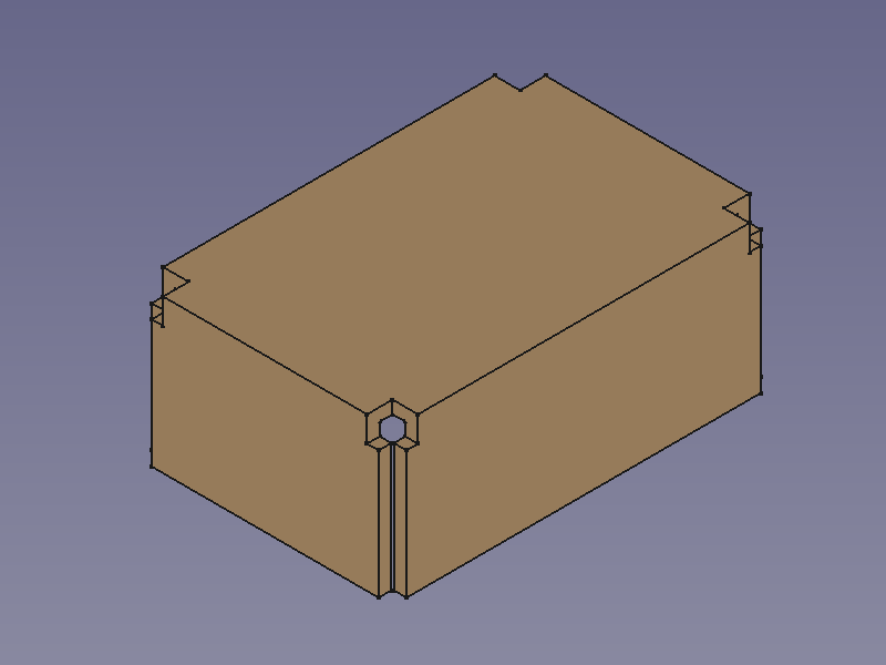
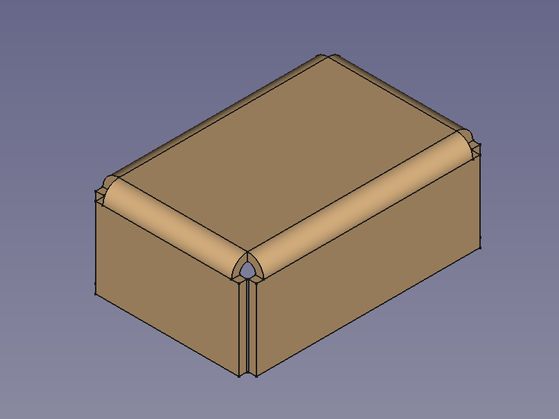
The ![]() SheetMetal AddBend command replaces sharp edges between between two sections (base plate/walls/flanges) of a sheet metal object with rounded bends. Without these bends the object will not be unfoldable.
SheetMetal AddBend command replaces sharp edges between between two sections (base plate/walls/flanges) of a sheet metal object with rounded bends. Without these bends the object will not be unfoldable.
This command is the third of three steps to convert a shell object made with the Part Workbench or PartDesign Workbench into an unfoldable sheet metal object:
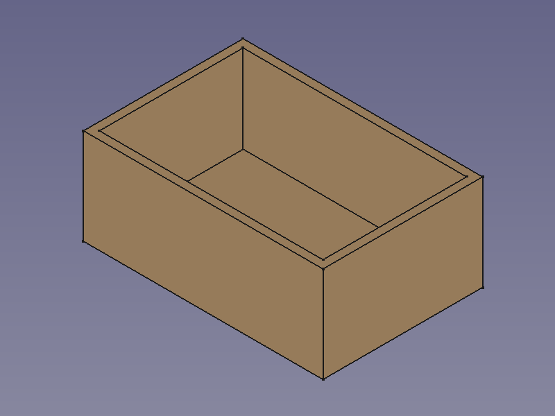
![]()
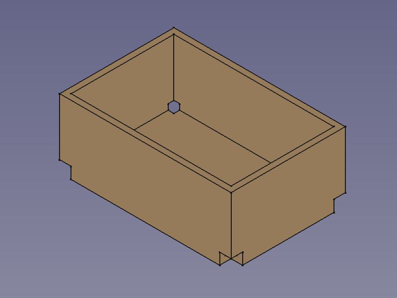
![]()
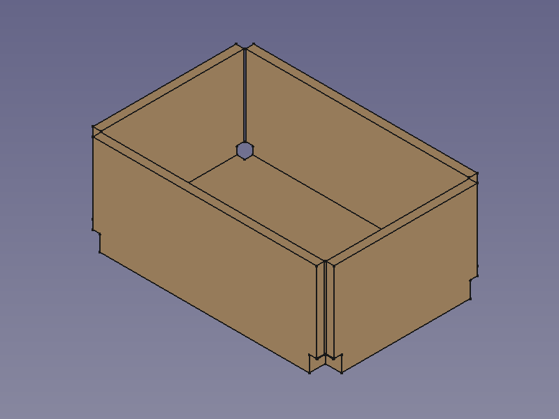
![]()
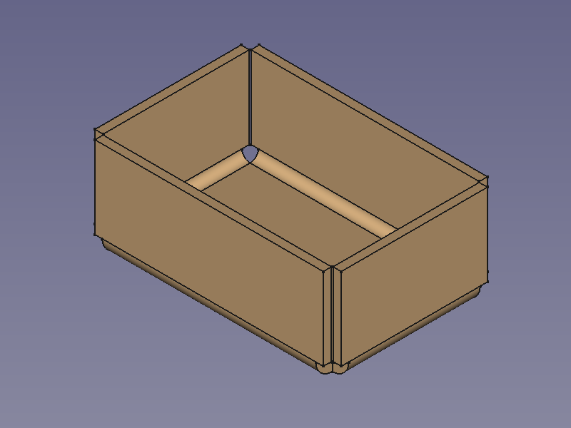
Make Bend - replace edges with bends
Usage
- Select one or more edges.
- There are several ways to invoke the command:
- The Bend sharp corner properties Task Panel opens (introduced in version 0.5.00).
- Optionally press the Select button to add more faces.
- Press the Preview button to finish the selection and display the changes.
- Optionally adjust the parameters in the Task Panel.
- Press the OK button to finish the command and close the Task Panel.
- A SolidBend object will be created consisting of one new bend at each selected edge.
- Optionally adjust the parameters in the Property View.
![]()
Notes
The commands ![]() SheetMetal AddRelief,
SheetMetal AddRelief, ![]() SheetMetal AddJunction, and
SheetMetal AddJunction, and ![]() SheetMetal AddBend work best with hollow cuboids i.e. shell objects with a constant thickness and only 90° angles between faces.
SheetMetal AddBend work best with hollow cuboids i.e. shell objects with a constant thickness and only 90° angles between faces.
See SheetMetal AddRelief for hints about creating shell objects of cuboids.
Properties
See also: Property View.
A SheetMetal SolidBend object is derived from a Part Feature object or, if it is inside a PartDesign Body, from a PartDesign Feature object, and inherits all its properties. It also has the following additional properties:
Data
Parameters
- Database Object (
LinkSub): "Base object". Links to the edges to be bent. - Dataradius (
Length): "Bend Radius". Default:1,00 mm. - Datathickness (
Length): "Thickness of sheetmetal". Default:1,00 mm.