SheetMetal AddRelief
This documentation is not finished. Please help and contribute documentation.
GuiCommand model explains how commands should be documented. Browse Category:UnfinishedDocu to see more incomplete pages like this one. See Category:Command Reference for all commands.
See WikiPages to learn about editing the wiki pages, and go to Help FreeCAD to learn about other ways in which you can contribute.
|
|
| Menu location |
|---|
| SheetMetal → Make Relief |
| Workbenches |
| SheetMetal |
| Default shortcut |
| S R |
| Introduced in version |
| - |
| See also |
| SheetMetal AddJunction, SheetMetal AddBend |
Description
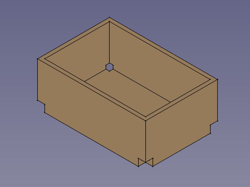
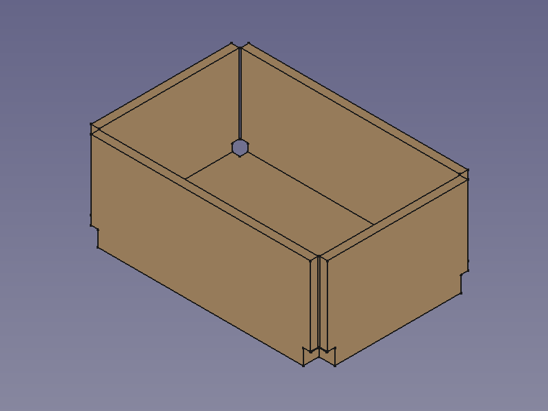
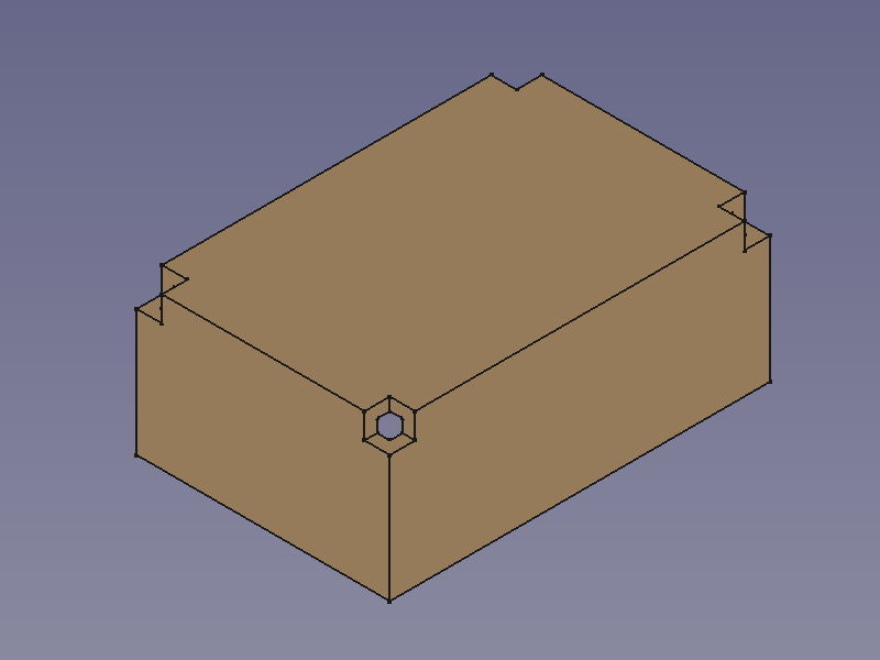
The ![]() SheetMetal AddRelief command creates corner reliefs, cutouts, at the points where three sections (base plate/walls/flanges) of a sheet metal object meet. Without these reliefs the object will not be unfoldable.
SheetMetal AddRelief command creates corner reliefs, cutouts, at the points where three sections (base plate/walls/flanges) of a sheet metal object meet. Without these reliefs the object will not be unfoldable.
This command is the first of three steps to convert a shell object made with the Part Workbench or PartDesign Workbench into an unfoldable sheet metal object:
![]()
![]()
![]()
Make Relief - cut off corners
Usage
- Select one or more corner vertex(es).
- There are several ways to invoke the command:
- Press the
 Make Relief button.
 - Select the SheetMetal → Make Relief option from the menu.
- Right-click in the Tree View or the 3D View and select the Sheet Metal → Make Relief option from the context menu.
- Use the keyboard shortcut: S then R.
- Press the
- The Corner relief on solid parameters Task Panel opens (introduced in version 0.5.00).
- Optionally press the Select button to add more vertices.
- Press the Preview button to finish the selection and display the changes.
- Optionally adjust the parameters in the Task Panel.
- Press the OK button to finish the command and close the Task Panel.
- A CornerRelief object will be created consisting of one new corner relief at each selected vertex.
- Optionally adjust the parameters in the Property View.

![]()
Notes
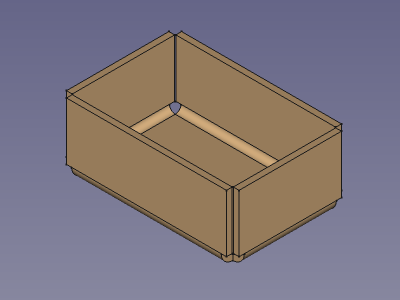
The commands ![]() SheetMetal AddRelief,
SheetMetal AddRelief, ![]() SheetMetal AddJunction, and
SheetMetal AddJunction, and ![]() SheetMetal AddBend work best with hollow cuboids i.e. shell objects with a constant thickness and only 90° angles between faces.
SheetMetal AddBend work best with hollow cuboids i.e. shell objects with a constant thickness and only 90° angles between faces.
Shell objects can be created with commands from the ![]() Part Workbench
or the
Part Workbench
or the ![]() PartDesign Workbench.
PartDesign Workbench.
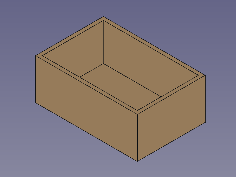
To create a hollow cuboid with the Part Workbench:
- Create a solid using either:
 Part Box.
 Part Extrude from:
- A
 Draft Rectangle.
 - A
 Draft Wire.
 - A
 Sketch.
- A
- Use
 Part Thickness to create a shell object from the solid (Typically with the thickness value of the sheet metal).
To create a hollow cuboid with the PartDesign Workbench:
- Create a solid using either:
 Additive Box.
 PartDesign Pad from a Sketch.
- Use
 PartDesign Thickness to create a shell object from the solid (Typically with the thickness value of the sheet metal).
Properties
See also: Property View.
A SheetMetal Relief object is derived from a Part Feature object or, if it is inside a PartDesign Body, from a PartDesign Feature object, and inherits all its properties. It also has the following additional properties:
Data
Parameters
- Database Object (
LinkSub): "Base Object". Links to the corner vertexes defining relief positions. - Datarelief (
Length): "Relief Size". Default:2,00 mm.