Part Thickness
|
|
| Menu location |
|---|
| Part → Thickness |
| Workbenches |
| Part |
| Default shortcut |
| None |
| Introduced in version |
| - |
| See also |
| Part Offset, PartDesign Thickness |
Description
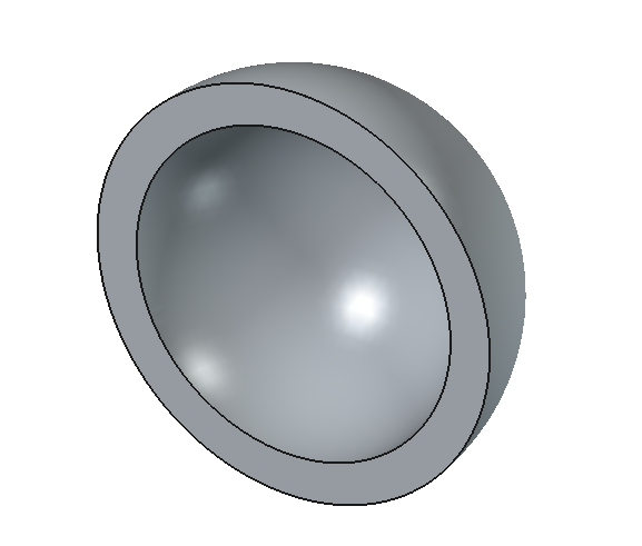
The Part Thickness command works on a solid shape and transforms it into a hollow object, giving to each of its faces a defined and constant thickness. On some solids it allows you to significantly speed up the work, and avoids making extrusions and pockets.
Hollowed out half of a sphere
Usage
- Select one or more faces of an existing solid.
- There are several ways to invoke the command:
- Press the
Thickness button.
- Select the Part →
Thickness option from the menu.
- Press the
- A Thickness object is created and the Thickness task panel opens.
- Set the parameters (see Options).
- Optionally press the Faces button to reselect one or more faces.
- Press OK to close the task panel.
Options
- Thickness: Wall thickness of the resulting object, set the desired value.
- A positive value will offset the faces outward
- A negative value will offset the faces inward
- Mode
- Skin: Only this mode is currently implemented in OCC.
- Pipe: This mode has no effect as it's currently not implemented in OCC.
- Recto verso: This mode has no effect as it's currently not implemented in OCC.
- Join type
- Arc: Removes the outer edges and creates a fillet with a radius equal to the thickness defined.
- Tangent: Results in sharp corners.
- Intersection: Results in sharp corners.
- Intersection: When enabled, self-intersections in some models are avoided.
- Self-intersection: This option is currently not implemented in OCC and should be left with the default value (false).
- Faces: Select the faces to be removed, then click Done.
- Update view: Automatically updates the view in real time.
Notes
- App Link objects linked to the appropriate object types can also be used as source objects.
- Complex shapes may produce bizarre, hard to predict results. Carefully inspect the resulting shape and save your work before applying the operation.
- As noted in the OCC documentation and mentioned in the Options section, some options are not implemented yet.
- Primitives: Box, Cylinder, Sphere, Cone, Torus, Tube, Create primitives, Shape builder
- Creation and modification: Create sketch, Extrude, Revolve, Mirror, Scale, Fillet, Chamfer, Make face from wires, Ruled Surface, Loft, Sweep, Section, Cross sections, 3D Offset, 2D Offset, Thickness, Projection on surface, Color per face
- Boolean: Make compound, Explode compound, Compound Filter, Boolean, Cut, Union, Intersection, Connect objects, Embed object, Cutout for object, Boolean fragments, Slice apart, Slice to compound, Boolean XOR, Check geometry, Defeaturing
- Other tools: Import CAD file, Export CAD file, Box selection, Create shape from mesh, Create points object from geometry, Convert to solid, Reverse shapes, Create simple copy, Create transformed copy, Create shape element copy, Refine shape, Set tolerance, Persistent section cut, Attachment…
- Preferences: Preferences, Fine tuning
- Getting started
- Installation: Download, Windows, Linux, Mac, Additional components, Docker, AppImage, Ubuntu Snap
- Basics: About FreeCAD, Interface, Mouse navigation, Selection methods, Object name, Preferences, Workbenches, Document structure, Properties, Help FreeCAD, Donate
- Help: Tutorials, Video tutorials
- Workbenches: Std Base, Assembly, BIM, CAM, Draft, FEM, Inspection, Material, Mesh, OpenSCAD, Part, PartDesign, Points, Reverse Engineering, Robot, Sketcher, Spreadsheet, Surface, TechDraw, Test Framework
- Hubs: User hub, Power users hub, Developer hub
