Part Slice
|
|
| Menu location |
|---|
| Part → Split → Slice to Compound |
| Workbenches |
| Part |
| Default shortcut |
| None |
| Introduced in version |
| 0.17 |
| See also |
| Part Boolean Fragments, Part XOR, Part Join features, Part Boolean |
Description
The ![]() Part Slice command splits shapes by intersection with other shapes. For example, for a box and a plane, a compound of two solids is created.
Part Slice command splits shapes by intersection with other shapes. For example, for a box and a plane, a compound of two solids is created.

Above: the pieces were moved apart manually afterwards, to reveal the slicing
There are two commands to slice a shape: ![]() Slice Apart and
Slice Apart and ![]() Slice to Compound. They both create a 'Slice' parametric feature, that puts the sliced pieces into a compound. However,
Slice to Compound. They both create a 'Slice' parametric feature, that puts the sliced pieces into a compound. However, ![]() Slice Apart explodes the resulting compound into separate objects. "Slice to Compound" is fully-parametric, and causes no trouble as the number of pieces changes. "Slice Apart" will not update the number of objects as the number of pieces changes.
Slice Apart explodes the resulting compound into separate objects. "Slice to Compound" is fully-parametric, and causes no trouble as the number of pieces changes. "Slice Apart" will not update the number of objects as the number of pieces changes.
The output shape occupies the same space as the original, but it is split where it intersects with other shapes. The split pieces are put into a compound (or compsolid), so the object appears to remain in one piece. You need to explode the compound to get the individual pieces. If you want to access the individual pieces in a parametric way you can use ![]() Part CompoundFilter for this purpose. For quick non-parametric access use
Part CompoundFilter for this purpose. For quick non-parametric access use ![]() Draft Downgrade.
Draft Downgrade.
The command has three modes: "Standard", "Split", and "CompSolid". There is no selection form, they are predefined but can be accessed after the operation on the resulting slices level.
"Standard" and "Split" differ by the action of the command on wires, shells and compsolids: if "Split", those are separated; if "Standard", they are kept together (get extra segments).
Compounding structure in "Standard" and "Split" modes follows the compounding structure of shape being sliced.
In "CompSolid" mode, the output is a compsolid (or a compound of compsolids, if the resulting solids form more than one island of connectedness). Compsolid is a set of solids connected by faces; they are related to solids like wires are related to edges, and shells are related to faces; the name is probably a shortened phrase "composite solid".
The overall action of the command is very similar to ![]() Part Boolean Fragments, except only the pieces from the first shape are in the result.
Part Boolean Fragments, except only the pieces from the first shape are in the result.
Usage
- Select the object to be sliced, first, and then some objects to slice with.
The order of selection is important. Compounds with self-intersections are not allowed (self-intersections sometimes can be accounted for by passing the compound through Part Boolean Fragments).
 - There are several ways to invoke the command:
- Press the
 Slice to Compound button.
 - Select the Part → Split → Slice to Compound option from the menu.
- Press the
- A parametric Slice object is created. Original objects are hidden, and the result of intersection is shown in 3D View.
Tree structure of Slice
The Slice command creates a sliced object. In the following example a cube is sliced by a face.
The slice is created and each piece of it is united in a Compound.

Properties
Slice
- DataBase: Object to be sliced.
- DataTools: List of objects to slice with.
- DataMode: "Standard", "Split", or "CompSolid". "Split" is default. Standard and Split differ by the action of the command on aggregation type shapes: if Split, those are separated; otherwise they are kept together (get extra segments).
- DataTolerance: "fuzziness" value. This is an extra tolerance to apply when searching for intersections, in addition to tolerances stored in the input shapes.
Example
Creating a Puzzle
- Switch to
 Sketcher Workbench
- Create a new sketch.
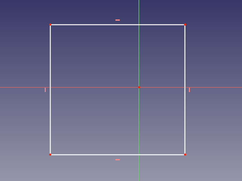
- Draw a rectangle that will outline the overall shape of the puzzle.
- Close the sketch.
- Switch to
 Part workbench.
- Select the sketch, and pick Part →
 Make face from wires.
- Select the sketch, and pick Part →
- Switch back to Sketcher Workbench
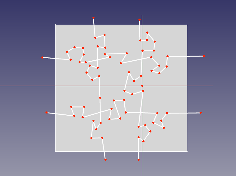
- Create another sketch on the same plane.
- Using polyline command, draw the lines that will split the puzzle into pieces.
- Switch back to Part Workbench.
- Select the splitter sketch, and apply Part Boolean Fragments. This will insert vertices where lines of splitter sketch intersect. Having them is essential for the next step to work.
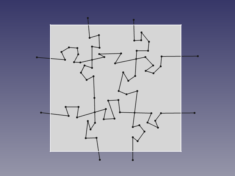
- Select the splitter sketch, and apply
- Select the rectangular face, and the BooleanFragments of splitter sketch, and apply Part Slice.
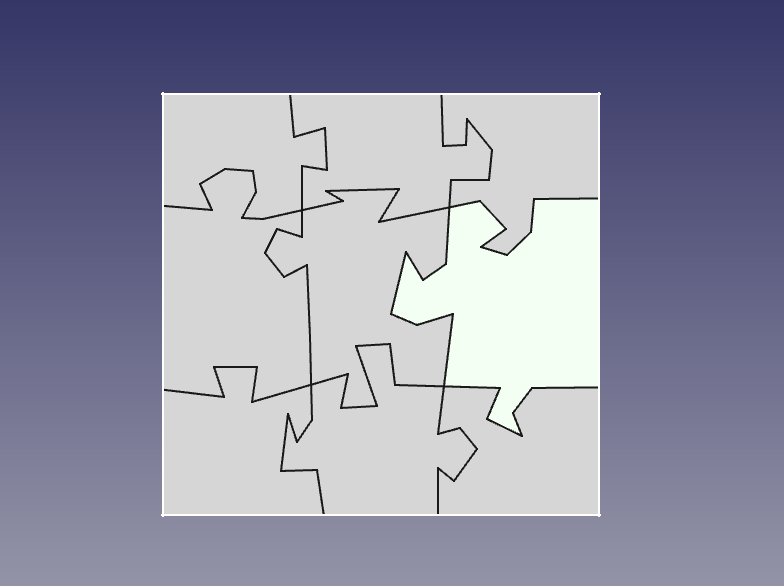
- Use
 Part ExplodeCompound on the sliced face, to break apart the compound made by Part Slice into individual pieces.


Note: Steps 5 and 6 can be done in single click using ![]() Part SliceApart
Part SliceApart
Notes
- Properties are accessible on the slices inner object, not on the result level.
- The Objects to slice with must completely separate the object to be sliced. Thus a cube cannot be sliced by a wire, but by a plane derived from an extruded wire for instance.
- Slicing object must pass Boolean Operations check. See
 Part CheckGeometry.
Scripting
The command can by used in macros and from the Python Console by using the following function:
BOPTools.SplitFeatures.makeSlice(name)
- Creates an empty Slice feature. The 'Base' and 'Tools' properties must be assigned explicitly, afterwards.
- Returns the newly created object.
Slice can also be applied to plain shapes, without the need to have a document object, via:
BOPTools.SplitAPI.slice(base_shape, tool_shapes, mode, tolerance = 0.0)
This can be useful for making custom Python scripted features.
Example:
import BOPTools.SplitFeatures
j = BOPTools.SplitFeatures.makeSlice(name= 'Slice')
j.Base = FreeCADGui.Selection.getSelection()[0]
j.Tools = FreeCADGui.Selection.getSelection()[1:]
The command itself is implemented in Python, see /Mod/Part/BOPTools/SplitFeatures.py (GitHub link) within the FreeCAD installation directory.
Tutorials
- FreeCad 0.18 Part WB using Slice and Slice Apart (English language), author: Ha Gei
- FreeCAD Slice und Slice Apart und andere Tricks (German language), author: Ha Gei
- Creation and modification: New Sketch, Extrude, Revolve, Mirror, Scale, Fillet, Chamfer, Face From Wires, Ruled Surface, Loft, Sweep, Section, Cross-Sections, 3D Offset, 2D Offset, Thickness, Project on Surface, Appearance per Face
- Boolean: Compound, Explode Compound, Compound Filter, Boolean Operation, Cut, Union, Intersection, Connect Shapes, Embed Shapes, Cutout Shape, Boolean Fragments, Slice Apart, Slice to Compound, Boolean XOR, Check Geometry, Defeaturing
- Other tools: Box Selection, Shape From Mesh, Points From Shape, Convert to Solid, Reverse Shapes, Simple Copy, Transformed Copy, Shape Element Copy, Refine Shape, Set Tolerance, Persistent Section Cut, Attachment
- Preferences: Preferences, Fine tuning
- Getting started
- Installation: Download, Windows, Linux, Mac, Additional components, Docker, AppImage, Ubuntu Snap
- Basics: About FreeCAD, Interface, Mouse navigation, Selection methods, Object name, Preferences, Workbenches, Document structure, Properties, Help FreeCAD, Donate
- Help: Tutorials, Video tutorials
- Workbenches: Std Base, Assembly, BIM, CAM, Draft, FEM, Inspection, Material, Mesh, OpenSCAD, Part, PartDesign, Points, Reverse Engineering, Robot, Sketcher, Spreadsheet, Surface, TechDraw, Test Framework
- Hubs: User hub, Power users hub, Developer hub