Reinforcement BarShapeCutList/it
|
|
| Posizione nel menu |
|---|
| Reinforcement → Sagomatura dei ferri |
| Ambiente |
| Reinforcement, Arch, BIM |
| Avvio veloce |
| Nessuno |
| Introdotto nella versione |
| 0.19 |
| Vedere anche |
| Disegna e dimensiona un'armatura, Distinta dei ferri |
Descrizione
Lo strumento Sagomatura dei ferri consente all'utente di creare una lista per il taglio e la piega delle barre d'armatura.
Questo comando fa parte dell'ambiente Reinforcement, un ambiente esterno che si può installare con ![]() Addon manager, tramite il menu Strumenti → Addon manager → Reinforcement.
Addon manager, tramite il menu Strumenti → Addon manager → Reinforcement.

Distinta di sagomatura dei ferri
Usage
1. Select ![]() Rebar and Rebar2 objects you want to include in Rebar Shape Cut List. Or select
Rebar and Rebar2 objects you want to include in Rebar Shape Cut List. Or select ![]() Structure objects to include
Structure objects to include ![]() Rebar and Rebar2 objects hosted by those into Rebar Shape Cut List. If nothing is selected, then Rebar Shape Cut List will be generated for all
Rebar and Rebar2 objects hosted by those into Rebar Shape Cut List. If nothing is selected, then Rebar Shape Cut List will be generated for all ![]() Rebar and Rebar2 objects present in the model.
Rebar and Rebar2 objects present in the model.
2. Then select ![]() Rebar Shape Cut List from the rebar tools.
Rebar Shape Cut List from the rebar tools.
3. A dialog box will pop-out on the screen as shown below.
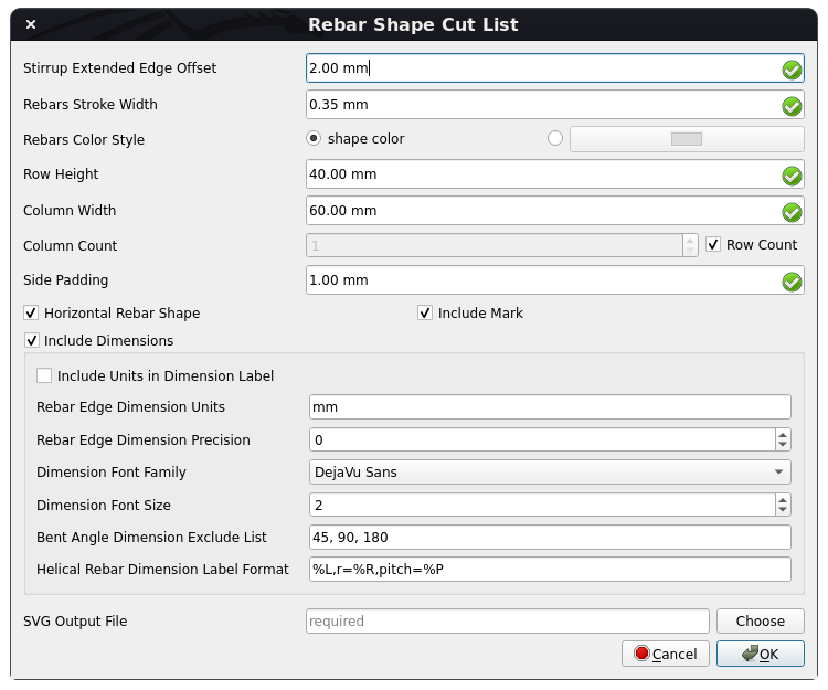
Dialog Box for the Reinforcement Bar Shape Cut List tool

4. Modify data to suit your requirements.
5. Click OK or Apply to generate Rebar Shape Cut List for rebars.
6. Click Cancel to exit the dialog box.
Properties
General:
- DatiStirrup Extended Edge Offset: The offset of extended end edges of the stirrup, so that end edges of the stirrup with a 90-degree bent angle do not overlap with stirrup edges.
- DatiRebars Stroke Width: The stroke-width of rebars in the rebar shape cut list.
- DatiRebars Color Style: The color style of rebars.
- DatiRow Height: The height of each row of rebar shape in the rebar shape cut list.
- DatiColumn Width: The width of each column of rebar shape in the rebar shape cut list.
- DatiColumn Count: The number of columns in the rebar shape cut list.
- DatiSide Padding: The padding on each side of the rebar shape.
- DatiHorizontal Rebar Shape: If True, then the rebar shape will be made horizontal by rotating the max length edge of the rebar shape.
- DatiInclude Mark: If it is set to True, then rebar.Mark will be included for each rebar shape in the rebar shape cut list.
- DatiSVG Output File: The output file to write generated rebar shape cut list SVG.
Dimension Data:
- DatiInclude Dimensions: If True, then each rebar edge dimensions and bent angle dimensions will be included in the rebar shape cut list.
- DatiInclude Units in Dimension Label: If it is True, then rebar edge length units will be shown in dimension label.
- DatiRebar Edge Dimension Units: The units to be used for rebar edge length dimensions.
- DatiRebar Edge Dimension Precision: The number of decimals that should be shown for rebar edge length as a dimension label.
- DatiDimension Font Family: The font-family of dimension text.
- DatiDimension Font Size: The font-size of dimension text.
- DatiBent Angle Dimension Exclude List: The list of bent angles to not include their dimensions.
- DatiHelical Rebar Dimension Label Format: The format of the helical rebar dimension label. e.g. "%L,r=%R,pitch=%P" where %L -> Length of helical rebar, %R -> Helix radius of helical rebar, %P -> Helix pitch of helical rebar.
Scripting
See also: Arch API, Reinforcement API and FreeCAD Scripting Basics.
The Reinforcement BarShapeCutList tool can be used in macros and from the Python console by using the following function:
Create Rebar Shape SVG
getRebarShapeSVG(
    rebar,
    view_direction: Union[FreeCAD.Vector, WorkingPlane.Plane] = FreeCAD.Vector(0, 0, 0),
    include_mark: bool = True,
    stirrup_extended_edge_offset: float = 2,
    rebar_stroke_width: float = 0.35,
    rebar_color_style: str = "shape color",
    include_dimensions: bool = True,
    rebar_dimension_units: str = "mm",
    rebar_length_dimension_precision: int = 0,
    include_units_in_dimension_label: bool = False,
    bent_angle_dimension_exclude_list: Tuple[float, ...] = (45, 90, 180),
    dimension_font_family: str = "DejaVu Sans",
    dimension_font_size: float = 2,
    helical_rebar_dimension_label_format: str = "%L,r=%R,pitch=%P",
    scale: float = 1,
    max_height: float = 0,
    max_width: float = 0,
    side_padding: float = 1,
    horizontal_shape: bool = False,
) -> ElementTree.Element
- Generates and returns a rebar shape SVG element for the given
rebarobject. rebarobject can be of type <ArchRebar._Rebar> or <rebar2.BaseRebar>, to generate its shape svg.view_directionspecifies the viewpoint direction for rebar shape. It can be of typeFreeCAD.VectororWorkingPlane.PlanethoughWorkingPlane.Planeis preferred.include_markspecifies if rebar.Mark is to be included in rebar shape SVG or not.stirrup_extended_edge_offsetis the offset of extended end edges of the stirrup, so that end edges of the stirrup with a 90-degree bent angle do not overlap with stirrup edges.rebar_stroke_widthspecifies the stroke-width of rebar in svg.rebar_color_stylespecifies the color style of rebar. It can be "shape color" or "color_name or hex_value_of_color". "shape color" means to select the color of the rebar shape.include_dimensionsspecifies if each rebar edge dimensions and bent angle dimensions are to be included in rebar shape SVG.rebar_dimension_unitsspecifies the units to be used for rebar length dimensions.rebar_length_dimension_precisionspecifies the number of decimals that should be shown for rebar length as a dimension label. Set it to None to use user preferred unit precision from FreeCAD unit preferences.include_units_in_dimension_labelspecifies if rebar length units is to be shown in dimension label.bent_angle_dimension_exclude_listspecifies the list of bent angles to not include their dimensions.dimension_font_familyspecifies the font-family of dimension text.dimension_font_sizespecifies the font-size of dimension text.helical_rebar_dimension_label_formatspecifies the format of helical rebar dimension label. E.g. "%L,r=%R,pitch=%P" where:
   %L -> Length of helical rebar
   %R -> Helix radius of helical rebar
   %P -> Helix pitch of helical rebar
scalespecifies the scale value to scale rebar SVG. The scale parameter helps to scale down rebar_stroke_width and dimension_font_size to make them resolution-independent. If max_height or max_width is set to a non-zero value, then the scale parameter will be ignored.max_heightspecifies the maximum height of rebar shape SVG. Set it to 0 to have rebar shape SVG height based on the scale parameter.max_widthspecifies the maximum width of rebar shape SVG. Set it to 0 to have rebar shape SVG width based on the scale parameter.side_paddingspecifies the padding on each side of the rebar shape.horizontal_shapespecifies if the rebar shape is to be made horizontal by rotating the max length edge of the rebar shape.
Example
from pathlib import Path
from xml.dom import minidom
from xml.etree import ElementTree

import Draft, Arch, Stirrup
from RebarShapeCutList import RebarShapeCutListfunc

Rect = Draft.makeRectangle(400, 400)
Structure = Arch.makeStructure(Rect, height=1600)
Structure.ViewObject.Transparency = 80
FreeCAD.ActiveDocument.recompute()

Rebar = Stirrup.makeStirrup(
    20, 20, 20, 20, 20, 90, 4, 8, 2, True, 10, Structure, "Face6"
)

rebar_shape_svg = RebarShapeCutListfunc.getRebarShapeSVG(
    Rebar,
    view_direction=FreeCAD.Vector(0, 0, 0),
    include_mark=True,
    stirrup_extended_edge_offset=2,
    rebar_stroke_width=0.35,
    rebar_color_style="shape color",
    include_dimensions=True,
    rebar_dimension_units="mm",
    rebar_length_dimension_precision=0,
    include_units_in_dimension_label=True,
    bent_angle_dimension_exclude_list=(45, 90, 180),
    dimension_font_family="DejaVu Sans",
    dimension_font_size=2,
    helical_rebar_dimension_label_format="%L,r=%R,pitch=%P",
    scale=1,
    max_height=100,
    max_width=100,
    side_padding=1,
    horizontal_shape=False,
)

output_file = str(Path.home() / "StirrupRebarShape.svg")
with open(output_file, "w", encoding="utf-8") as f:
    f.write(
        minidom.parseString(
            ElementTree.tostring(rebar_shape_svg, encoding="unicode")
        ).toprettyxml(indent="  ")
    )
Create Rebar Shape Cut List SVG
getRebarShapeCutList(
    base_rebars_list: Optional[List] = None,
    view_directions: Union[
        Union[FreeCAD.Vector, WorkingPlane.Plane],
        List[Union[FreeCAD.Vector, WorkingPlane.Plane]],
    ] = FreeCAD.Vector(0, 0, 0),
    include_mark: bool = True,
    stirrup_extended_edge_offset: float = 2,
    rebars_stroke_width: float = 0.35,
    rebars_color_style: str = "shape color",
    include_dimensions: bool = True,
    rebar_edge_dimension_units: str = "mm",
    rebar_edge_dimension_precision: int = 0,
    include_units_in_dimension_label: bool = False,
    bent_angle_dimension_exclude_list: Union[Tuple[float, ...], List[float]] = (
        45,
        90,
        180,
    ),
    dimension_font_family: str = "DejaVu Sans",
    dimension_font_size: float = 2,
    helical_rebar_dimension_label_format: str = "%L,r=%R,pitch=%P",
    row_height: float = 40,
    column_width: float = 60,
    column_count: Union[int, Literal["row_count"]] = "row_count",
    side_padding: float = 1,
    horizontal_rebar_shape: bool = True,
    output_file: Optional[str] = None,
) -> ElementTree.Element
- Generate and return rebar shape cut list SVG element for given
base_rebars_list. base_rebars_listis a list of <ArchRebar._Rebar> or <rebar2.BaseRebar> objects, to generate their RebarShape cut list. If not provided, then all ArchRebars and rebar2.BaseRebar objects with unique Mark from ActiveDocument will be selected and rebars with no Mark assigned will be ignored.view_directionsis a list of viewpoint directions for each rebar shape. It can be either of typeFreeCAD.VectororWorkingPlane.PlaneOR their list. Keep itFreeCAD.Vector(0, 0, 0)to automatically choose view_directions.include_markspecifies if rebar.Mark is to be included for each rebar shape in rebar shape cut list SVG or not.stirrup_extended_edge_offsetspecifies the offset of extended end edges of the stirrup, so that end edges of the stirrup with a 90-degree bent angle do not overlap with stirrup edges.rebars_stroke_widthspecifies the stroke-width of rebars in rebar shape cut list SVG.rebars_color_stylespecifies the color style of rebars. It can be "shape color" or "color_name or hex_value_of_color". "shape color" means to select the color of the rebar shape.include_dimensionsspecifies if each rebar edge dimensions and bent angle dimensions are to be included in the rebar shape cut list.rebar_edge_dimension_unitsspecifies the units to be used for rebar edge length dimensions.rebar_edge_dimension_precisionspecifies the number of decimals that should be shown for rebar length as a dimension label. Set it to None to use user preferred unit precision from FreeCAD unit preferences.include_units_in_dimension_labelspecifies if rebars edge length units is to be shown in dimension label.bent_angle_dimension_exclude_listspecifies the list of bent angles to not include their dimensions.dimension_font_familyspecifies the font-family of dimension text.dimension_font_sizespecifies the font-size of dimension text.helical_rebar_dimension_label_formatspecifies the format of helical rebar dimension label. E.g. "%L,r=%R,pitch=%P" where:
   %L -> Length of helical rebar
   %R -> Helix radius of helical rebar
   %P -> Helix pitch of helical rebar
row_heightspecifies the height of each row of rebar shape in the rebar shape cut list.column_widthspecifies the width of each row of rebar shape in the rebar shape cut list.column_countspecifies the number of columns in the rebar shape cut list. Set it to "row_count" to have column_count <= row_countside_paddingspecifies the padding on each side of the rebar shape in the rebar shape cut list.horizontal_rebar_shapespecifies if the rebar shape is to be made horizontal by rotating the max length edge of the rebar shape.output_filespecifies the output file to write generated rebar shape cut list SVG.
Example
from pathlib import Path

import FreeCAD, Draft, Arch
from ColumnReinforcement import SingleTie
from RebarShapeCutList import RebarShapeCutListfunc

Rect1 = Draft.makeRectangle(400, 400)
Structure1 = Arch.makeStructure(Rect1, height=1600)
Structure1.ViewObject.Transparency = 80
Rect2 = Draft.makeRectangle(500, 500)
Structure2 = Arch.makeStructure(Rect2, height=1600)
Structure2.ViewObject.Transparency = 80
Structure2.Placement = FreeCAD.Placement(FreeCAD.Vector(1000, 0, 0), FreeCAD.Rotation(FreeCAD.Vector(0, 0, 1), 0))
FreeCAD.ActiveDocument.recompute()

# Create Straight Rebars
rebar_group = SingleTie.makeSingleTieFourRebars(
    l_cover_of_tie=40,
    r_cover_of_tie=40,
    t_cover_of_tie=40,
    b_cover_of_tie=40,
    offset_of_tie=100,
    bent_angle=135,
    extension_factor=8,
    dia_of_tie=8,
    number_spacing_check=True,
    number_spacing_value=10,
    dia_of_rebars=16,
    t_offset_of_rebars=40,
    b_offset_of_rebars=40,
    rebar_type="StraightRebar",
    hook_orientation="Top Inside",
    hook_extend_along="x-axis",
    l_rebar_rounding=None,
    hook_extension=None,
    structure=Structure1,
    facename="Face6",
).rebar_group

# Assign Mark to straight rebars
for straight_rebar in rebar_group.RebarGroups[1].MainRebars:
    straight_rebar.Mark = "main_sb"

# Create LShaped Rebars with hook along x-axis
rebar_group = SingleTie.makeSingleTieFourRebars(
    l_cover_of_tie=40,
    r_cover_of_tie=40,
    t_cover_of_tie=40,
    b_cover_of_tie=40,
    offset_of_tie=100,
    bent_angle=90,
    extension_factor=8,
    dia_of_tie=8,
    number_spacing_check=True,
    number_spacing_value=10,
    dia_of_rebars=16,
    t_offset_of_rebars=-40,
    b_offset_of_rebars=-40,
    rebar_type="LShapeRebar",
    hook_orientation="Top Outside",
    hook_extend_along="x-axis",
    l_rebar_rounding=2,
    hook_extension=100,
    structure=Structure2,
    facename="Face6",
).rebar_group

# Assign Mark to lshape rebars
for lshape_rebar in rebar_group.RebarGroups[1].MainRebars:
    lshape_rebar.Mark = "main_lb"

output_file = str(Path.home() / "RebarShapeCutList.svg")

# Create Rebar Shape Cut List for all base rebars in model
RebarShapeCutListfunc.getRebarShapeCutList(
    base_rebars_list=None,
    view_directions=FreeCAD.Vector(0, 0, 0),
    include_mark=True,
    stirrup_extended_edge_offset=2,
    rebars_stroke_width=0.35,
    rebars_color_style="shape color",
    include_dimensions=True,
    rebar_edge_dimension_units="mm",
    rebar_edge_dimension_precision=0,
    include_units_in_dimension_label=False,
    bent_angle_dimension_exclude_list=(45, 90, 180),
    dimension_font_family="DejaVu Sans",
    dimension_font_size=2,
    helical_rebar_dimension_label_format="%L,r=%R,pitch=%P",
    row_height=40,
    column_width=60,
    column_count="row_count",
    side_padding=1,
    horizontal_rebar_shape=True,
    output_file=output_file,
)