Assembly3 ConstraintCoincidence/pl
Ta dokumentacja nie jest ukończona. Prosimy o pomoc w tworzeniu dokumentacji.
Strona Model polecenia GUI wyjaśnia jak powinny być dokumentowane polecenia. Przejrzyj stronę Category:UnfinishedDocu, aby zobaczyć więcej niekompletnych stron, takich jak ta. Zobacz stronę Category:Command Reference aby poznać wszystkie komendy.
Zobacz stronę wytycznych Wiki dla FreeCAD aby dowiedzieć się, jak edytować strony Wiki, i przejdź do strony Pomóż w rozwoju FreeCAD, aby dowiedzieć się o innych sposobach, w jakie możesz wnieść swój wkład.
|
|
| Menu location |
|---|
| None |
| Workbenches |
| Assembly3 |
| Default shortcut |
| None |
| Introduced in version |
| - |
| See also |
| None |
Description
This tool links two or more objects of an assembly and matches their orientations. The selected elements of each object or more precisely their implicit coordinate systems (ICSs) are used to position one object in relation to another.
Assuming the first object is already locked in place by the ![]() Lock constraint then the following objects are moved to positions where the x-y-planes of all ICSs are coplanar and the z-axes are collinear.
Lock constraint then the following objects are moved to positions where the x-y-planes of all ICSs are coplanar and the z-axes are collinear.
An option for this link is to set a distance between the x-y-planes and making them parallel.
The angle between their x-axes (and y-axes as well) are not defined. Related to the first object the following objects can still spin around the z-axis. This is leaving 1 degree of freedom (DOF) for each link unconstrained.
This link can be used as a hinge in kinematics.
The rotation can be stopped by switching Lock Angle to true in the properties panel and the angle can be set to a specific value. With controlled value the link can be used as an actuator in a kinematic system.
Usage
- Place two or more objects into an assembly.
- Select one planar face element of each object.
- Activate the
 Assembly3 ConstraintCoincidence command using:
- The Create "PlaneCoincident" constraint button.
- The
Kinematic Equivalent
Used in kinematic context this constraint resembles a hinge or a revolute joint when used with arcs and circles.
In real life the shapes of the objects allow rotation and prevent sliding and in this case arcs and circles are utilised to simulate this.
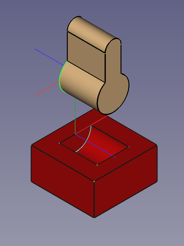
![]()
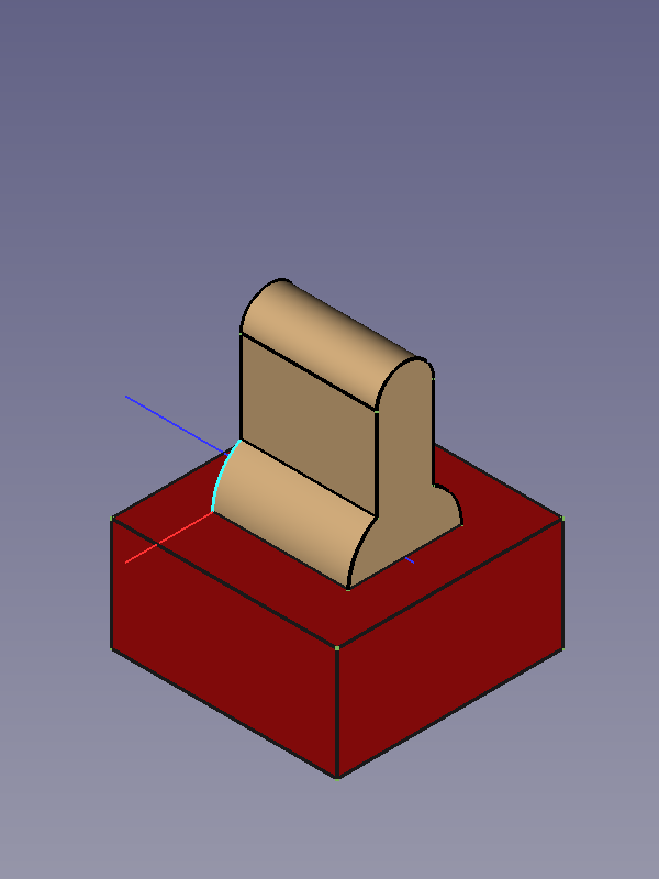
Constrained objects before and after running the solver
- Jak zacząć
- Instalacja: Pobieranie programu, Windows, Linux, Mac, Dodatkowych komponentów, Docker, AppImage, Ubuntu Snap
- Podstawy: Informacje na temat FreeCAD, Interfejs użytkownika, Profil nawigacji myszką, Metody wyboru, Nazwa obiektu, Edytor ustawień, Środowiska pracy, Struktura dokumentu, Właściwości, Pomóż w rozwoju FreeCAD, Dotacje
- Pomoc: Poradniki, Wideo poradniki
- Środowiska pracy: Strona Startowa, Złożenie, BIM, CAM, Rysunek Roboczy, MES, Inspekcja, Siatka, OpenSCAD, Część, Projekt Części, Punkty, Inżynieria Wsteczna, Robot, Szkicownik, Arkusz Kalkulacyjny, Powierzchnia 3D, Rysunek Techniczny, Test Framework