Assembly3 ConstraintCoincidence
This documentation is not finished. Please help and contribute documentation.
GuiCommand model explains how commands should be documented. Browse Category:UnfinishedDocu to see more incomplete pages like this one. See Category:Command Reference for all commands.
See WikiPages to learn about editing the wiki pages, and go to Help FreeCAD to learn about other ways in which you can contribute.
|
|
| Menu location |
|---|
| None |
| Workbenches |
| Assembly3 |
| Default shortcut |
| None |
| Introduced in version |
| - |
| See also |
| None |
Description
This tool links two or more objects of an assembly and matches their orientations. The selected elements of each object or more precisely their implicit coordinate systems (ICSs) are used to position one object in relation to another.
Assuming the first object is already locked in place by the ![]() Lock constraint then the following objects are moved to positions where the x-y-planes of all ICSs are coplanar and the z-axes are collinear.
Lock constraint then the following objects are moved to positions where the x-y-planes of all ICSs are coplanar and the z-axes are collinear.
An option for this link is to set a distance between the x-y-planes and making them parallel.
The angle between their x-axes (and y-axes as well) are not defined. Related to the first object the following objects can still spin around the z-axis. This is leaving 1 degree of freedom (DOF) for each link unconstrained.
This link can be used as a hinge in kinematics.
The rotation can be stopped by switching Lock Angle to true in the properties panel and the angle can be set to a specific value. With controlled value the link can be used as an actuator in a kinematic system.
Usage
- Place two or more objects into an assembly.
- Select one planar face element of each object.
- Activate the
 Assembly3 ConstraintCoincidence command using:
- The Create "PlaneCoincident" constraint button.
- The
Kinematic Equivalent
Used in kinematic context this constraint resembles a hinge or a revolute joint when used with arcs and circles.
In real life the shapes of the objects allow rotation and prevent sliding and in this case arcs and circles are utilised to simulate this.
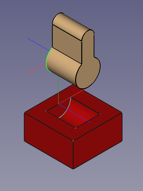
![]()
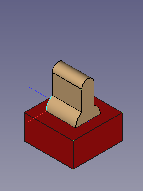
Constrained objects before and after running the solver
- Getting started
- Installation: Download, Windows, Linux, Mac, Additional components, Docker, AppImage, Ubuntu Snap
- Basics: About FreeCAD, Interface, Mouse navigation, Selection methods, Object name, Preferences, Workbenches, Document structure, Properties, Help FreeCAD, Donate
- Help: Tutorials, Video tutorials
- Workbenches: Std Base, Assembly, BIM, CAM, Draft, FEM, Inspection, Material, Mesh, OpenSCAD, Part, PartDesign, Points, Reverse Engineering, Robot, Sketcher, Spreadsheet, Surface, TechDraw, Test Framework
- Hubs: User hub, Power users hub, Developer hub