Assembly3 Workbench
Introduction
![]() Assembly3 is an external workbench that is used to perform assembly of different bodies contained in a single file or in multiple documents. The workbench is based on several core function changes done for the version of FreeCAD 0.19 (e.g. App Link), so the Assembly3 Workbench can not be used with earlier versions.
Assembly3 is an external workbench that is used to perform assembly of different bodies contained in a single file or in multiple documents. The workbench is based on several core function changes done for the version of FreeCAD 0.19 (e.g. App Link), so the Assembly3 Workbench can not be used with earlier versions.
The main features of the Assembly3 Workbench are
- dynamic/interactive solver. This means you can move parts with the mouse while the solver constrains the motion. This allows for example to connect a wheel to an axis and turn the wheel interactively with the mouse.
- links. This means you can use one single part, e.g. a screw multiple times in an assembly (at different places) without duplicating geometry.
- external links. It is possible to have a freecad document that only contains an assembly and no parts. All parts could be in separate files. The files even could be in a library or anywhere else in the file system. The only requirement is that the file must be loaded when the link is made. After the link is made, the file must be open to make updates to the links involving the file. Assembly3 solves this by opening files in the background as required.
- hierarchical assemblies. As in real life a mechanical assembly may consist of sub-assemblies. Those might consists of sub-assemblies again and so on.
- assembly freeze. As the CPU can only handle a restricted number of concurrent constraints in real time, to freeze an assembly allows to use constraints even for large assemblies. By freezing finished assemblies or constraints that are not required to remain dynamic (e.g. welded, bolted or glued parts) those are excluded from update calculations and considered fixed geometry by the Assembly3 solver.
- Note that other approaches offer different solution to this problem, e.g. the
 Assembly4 Workbench.
- Note that other approaches offer different solution to this problem, e.g. the
Toolbars
As of 2020 the Assembly3 workbench features the following toolbars.
Main Toolbar
- The Main Toolbar contains tools that cover the most often used features of the workbench. The tooltips will give the keyboard short cuts.
 Create assembly: Add an assembly folder
 Group objects: Group objects
 Create element: Create element.
- Import from STEP. This has two settings
 Import from STEP: Import STEP files
 Import as multi-document: Import assemblies from STEP into separate documents
 Resolve constraints: Resolve constraints
 Quick solve: Quick resolve constraints
 Move part: Move parts in 3D, this is specific to Assembly3
 Axial move: Axial move parts in 3D, this is the classical tool available elsewhere in FreeCAD
 Quick move: This will attach the part selected in the tree to the mouse cursor. It will change the position of the part when you click.
- Often added parts are stacked upon each other in the origin. Use this function to grab a part you can not see.
 Lock mover: Lock mover for fixed part. Toggle Button. When this is un-selected you can move the parts that have a "Locked" constraint.
 Toggle part visibility: This toggles the visiblity of the selected part on/off.
- Note that this differs from using space. Using space with selected items from a sub-assembly in the 3D view often does not behave as expected. Use this function in those cases (or shortcut A-Space)
 Trace part move: Trace part move (TBD)
 Auto recompute: Auto recompute. Usually enabled.
- May be un-selected when repairing constraints or fixing parts where the solver gives a "do not converge" message (e.g. by turning the part 180deg)
 Smart recompute: Smart recompute. Usually enabled.
 Auto fix element: Element Auto Fixing. Experimental feature in 0.19_pre
- Element Style. This has two settings
 Auto element visibility: Auto element visibility
 Show element coordinate system: Show element coordinate system
- Workplane and origin. Adds a workplane, placement or origin. A part must be selected. This has five settings
 Add workplane: Add workplane
 Add XZ workplane: Add XZ workplane
 Add ZY workplane: Add YZ workplane
 Add placement: Add placement
 Add Origin: Add Origin
 Move item up: Move selected tree item up
 Move item down: Move selected tree item down
- Allows to sort Parts, Elements or Constraints in the tree. Element roll over (top to bottom and vice versa). Only works for a single selection.
 Multiply constraint: Multiply Constraint. This can be selected if multiple parts and suitable Elements are present.
- It is used e.g. to assign multiple fasteners of the same type into multiple holes with one constraint.
Main Constraints Toolbar
- Some tools are actually a menu for more tools.
 Locked: Add a "Locked" constraint to fix one or more parts.
- You must select a geometry element of the part.
- If you fix a vertex or an edge the part is still free to rotate around the vertex or edge.
- Fixing a face will completely lock the part.
 Plane Alignment: Add a "Plane alignment" constraint to align planar faces of two or more parts.
- The faces become coplanar or parallel with an optional distance.
 Plane Coincidence: Add a "Plane coincidence" constraint to coincide planar faces of two or more parts.
- The faces are coincided at their centers with an optional distance.
- Attachment. This has two settings
 Attachment: Add an "Attachment" constraint to attach two parts with the selected geometry elements.
- This constraint completely fixes the parts relative to each other.
 AttachmentOffset: Same as "Attachment" constraint, but maintaining the current relative placement of the involved parts by applying an element offset.
- This constraint completely fixes the parts relative to each other.
 Axial Alignment: Add an "Axial alignment" constraint to align edges/faces of two or more parts.
- The constraint accepts
- linear edges, which become collinear,
- planar faces, which are aligned using their surface normal axis,
- and cylindrical face, which are aligned using the axial direction.
- Different types of geometry elements can be mixed.
- The constraint accepts
 Same orientation: Add a "Same orientation" constraint to align faces of two or more parts.
- The planes are aligned to have the same orientation (i.e. rotation)
 Multi parallel: Add a "Multi parallel" constraint to make planar faces or linear edges of two or more parts parallel.
 Angle: Add an "Angle" constraint to set the angle of planar faces or linear edges of two parts.
 Perpendicular: Add a "Perpendicular" constraint to make planar faces or linear edges of two parts perpendicular.
 Points coincident: Add a "Point coincident" constraint to coincide two points in 2D or 3D.
 Point on plane: Add a "Point on plane" to constrain one or more point onto a plane.
 Point on line: Add a "Point on line" to constrain a point onto a line in 2D or 3D.
 Point on circle: Add a "Point on circle" to constrain one or more points on to a clyndrical surface defined by a cricle.
- Note that you must select a point (any geometry element can define a point), and then select the circle (or clyndrical surface),
- after which you can add more points to your selection if you want.
 Points distance: Add a "Points distance" to constrain the distance of two or more points.
 Point plane distance: Add a "Point plane distance" to constrain the distance between one or more points and a plane.
 Point line distance: Add a "Point line distance" to constrain the distance between a point and a linear edge in 2D or 3D.
 Symmetric: Add a "Symmetric" constraint to make geometry elements of two parts symmetric about a plane.
- The supported elements are linear edge and planar face.
 More: Toggle toolbars for more constraints
- Not really a constraint but a toggle switch to show/hide the Additional Constraints Toolbars.
Additional Constraints Toolbars


 (Assembly3 Constraints2)


 (Assembly3 Sketch Constraints)
- You can enable these by selecting the More button on the Main Constraints toolbar.
- Point distance: Add a "Point distance" to constrain the distance of two points in 2D or 3D.
- Equal angle: Add an "Equal angle" to equate the angles between two lines or normals.
- Points symmetric: Add a "Points symmetric" constraint to make two points symmetric about a plane.
- () Symmetric horizontal: Symmetric horizontal
- () Symmetric vertical: Symmetric vertical
- Symmetric line: Add a "Symmetric line" constraint to make two points symmetric about a line.
- Points horizontal: Add a "Points horizontal" constraint to make two points horizontal with each other when projected onto a plane.
- Points vertical: Add a "Points vertical" constraint to make two points vertical with each other when projected onto a plane.
- Line horizontal:Add a "Line horizontal" constraint to make a line segment horizontal when projected onto a plane.
- Line vertical: Add a "Line vertical" constraint to make a line segment vertical when projected onto a plane.
- Arc line tangent: Add an "Arc line tangent" constraint to make a line tangent to an arc at the start or end point of the arc.
- Sketch plane: Add a "Sketch plane" to define the work plane of any draft element inside or following this constraint.
- Add an empty "Sketch plane" to undefine the previous work plane.
- Line length: Add a "Line length" constrain the length of a non-subdivided Draft.Wire.
- Equal length: Add an "Equal length" constraint to make two lines of the same length.
- Length ratio: Add a "Length ratio" to constrain the length ratio of two lines.
- Length difference: Add a "Length difference" to constrain the length difference of two lines.
- Length Equal Point Line Distance: Add a "Length Equal Point Line Distance" to constrain the distance
- between a point and a line to be the same as the length of a another line.
- ( )Equal Line Arc Length: Add an "Equal Line Arc Length" constraint to make a line of the same length as an arc.
- Mid point: Add a "Mid point" to constrain a point to the middle point of a line.
- Diameter: Add a "Diameter" to constrain the diameter of a circle/arc.
- Equal radius: Add an "Equal radius" constraint to make two circles/arcs of the same radius.
- Points project distance: Add a "Points project distance" to constrain the distance of two points projected on a line.
- Equal point line distance: Add an "Equal point line distance" to constrain the distance
- between a point and a line to be the same as the distance between another point and line.
- Colinear: Add a "Colinear" constraint to make two lines collinear.
- The Constraints Toolbars will be the main interface used when assembling parts.
- They are greyed out by default but are activated once at least one face, line or point of a part is selected.
- Generally you select the Elements that should be joined and then select the constraint type.
- The different colored frames mark different characteristics of the constraints:
- whether 2D/3D or if more than 2 Elements can be added.
- A detailed description can be found in the GitHub wiki.
- Theses functions are useful when working with an assembly with a hierarchy of linked external files
 Go to relation: Reveals the Relations group (hidden by default) and selects a relation object.
 Select linked object: Selects the linked object and switches to its document. introduced in 0.19
 Select linked final: Selects the deepest linked object and switches to its document. introduced in 0.19
Measurement Toolbar
- The Measurement toolbar adds functions to measure the distance or the angle between two objects
 Measure points: Add a "Measure points" to measure the distance of two points in 2D or 3D.
 Measure point to line: Add a "Measure point to line" to measure the distance between a point and a linear edge in 2D or 3D.
 Measure point to plane: Add a "Measure point to plane" to measure the distance between a point and a plane.
 Measure angle: Add a "Measure angle" to measure the angle of planar faces or linear edges of two parts.
- There is no function to measure a radius or diameter.
- The measurement tools survive part changes, e.g. the distance between edges of a cube when the cube is re-sized.
- As the constraints the calculations are done in real time and updated upon any change. Behind the scenes, the function is very similar to the constraints. The distance or angle is calculated between Elements in the same way as for constraints. The display in the tree works in the same way.
As usual you can modify the tool bars and add or remove single tools. Be sure to check the menu Assembly3 for functions that may not be present in the tool bars.
Constraints
The designer uses constraints to achieve the desired result for the relation of two parts. The art is the selection of the right constraints best suited to deal with each problem. Each eliminated DOF should in theory only be eliminated once between two objects, but in practice with many CAD tools selected constraints cause over-constrained combinations, often compensated by complex algorithms, sometimes not. Assembly3 does use algorithms to detect and compensate over-constraints, but clearly they are not very matured yet. So in practice for Assembly3 constraints avoid trouble by being aware of how many degrees of freedom (DOF) have been used and which ones are still to be locked down by constraints. No part should have a connection by constraints using more than 6 DOF.
- Note: If the solver meets a combination that can not be solved, it will give an error. It is very difficult for the solver to find out what caused the problem, so typically from this error given it will not be clear where the problem is. In larger assemblies this can lead to complex problem searches. Unfortunately there is no easy way to avoid this. However, it helps to be fully aware how the system works (.e.g see Elements below), use clear names for all components involved and only ever add additional constraints when the solver solves the current assembly. Very helpful to track down a problem is the "ContexMenu/Deactivate" function of each constraint.
Assembly3 Constraints define restrictions in the position or orientation between two Elements. Some constraints even work with more than two Elements. An Elements can be a face, a line or edge or a point of a part. Generally constraints are defined by selecting the desired Elements and then select the constraint from the Constraints toolbar.
- Fixes 6 DOF, leaves 0 DOF:
- Lock: The lock constraint fixes all DOFs for a face. It should be used for one base part in each assembly. You may also want to enable the "MoveLock" function (in the tool bar) so that the part can not be moved accidentially. Normally it does not matter which face/line/point you use to fix a part. Also note that the lock is only valid for the direct assembly, i.e. in case of a sub-assembly the parent assembly would still require a locked part on its own.
- Attachment: Makes both elements coordinate systems equal for all axes. This is computation wise the most inexpensive function and should be used where ever possible. Note that you could use the element properties to compensate for offsets and angles if the two elements are not perfectly aligned.
- Fixes 5 DOF, leaves 1 DOF:
- Plane Coincident: fixes Tx,Ty,Tz, Rx,Ry. Only Rz is free. There remains the rotation around the normal passing through the ‘‘center of the plane’’.
- Fixes 4 DOF, leaves 2 DOF:
- Axial Alignment: fixes Tx,Ty, Rx,Ry. Only Tz, Rz are free. There remains the rotation around the axis of the shape and the translation along this same axis. Two PointOnLine constraints (if the two points are different) give the same result. The '‘Colinear'’ constraint too.
- PointOnLine: This eliminates the translation and rotation along the normals to the reference line. Only the translation and rotation along the line axis is allowed.
- Fixes 3 DOF, leaves 3 DOF:
- Same Orientation: fixes Rx,Rz,Rz. All T's remain free.
- Points Coincident: fixes Tx,Ty,Tz. All R's remain free.
- PointOnPoint constraint eliminates the 3 translations.
- Plane Alignment: fixes Tz, Rx,Ry (plane motion). This eliminates the translation along the normal to the reference plane and the two rotations around the axes of this plane.
- Fixes 2 DOF, leaves 4 DOF:
- Multi Parallel: fixes Rx,Ry. all T's and Rz remain. This eliminates the two rotations around the axes of the reference plane.
- Fixes 1 DOF, leaves 5 DOF:
- Points in Plane: Fixes Tz. This eliminates the translation along the normal to the reference plane.
- Points Distance: fixes the distance between the Element origins.
- This gives you more freedom than Points in Plane
Other
- Points on Circle: fixes Tz and partially Tx,Ty. Freezes the point translation (or several points) on a circle or disk area. You must pick the circle second. This leaves all rotations free and gives limited translation in the circle reference plane.
: Note: In the following list Tx,Ty,Tz and Rx,Ry,Rz are used to describe translations and rotations about the reference coordinate systems of the involved Element's. This is not always exact or fully defined, e.g. when a line is involved it is not defined if it runs in X, Y or any angle in betweeen. The system is used for bevity and easy comparison in favour of a correct but more complex definition. So Z is generally the normal direction of any faces involved. Please feel free to modify this with a better approach with improved readability.
Elements
Elements is a specific term used in the Assembly3 workbench and it is important to understand Elements for understanding how Assembly3 should be used.
It is helpul to think of an Element as a general word for a 'selectable item' of a part, i.e. a face, an edge, a circle or a corner or other point. The items you select to constrain them, are those Elements. In the tree an Assembly folder has three sub-folders. Beside 'Parts' and 'Constraints' there is a folder named 'Elements', which is emtpy as long as there are no constraints added. When adding a constraint the constraint itself gets two (or more) leafs, these are the selected 'Elements'. Also these get added in the 'Elements' folder which is just a list of all Elements used in the assembly. Its a good idea to change their names (with F2 key), especially in bigger assemblies.
Let's look at an example
- Create a new file and add from the Part workbench a cube and a cylinder. We will stack the cylinder onto the cube. First we fix the base part, in out case the cube. Select the bottom face of the cube and select the "Locked" constraints (first icon in the Constraints toolbar). Select the top face of the cylinder and the top face of the cube. Then select the "Plane Coincident" constraint. Now the cylinder is moved into the cube and in the tree a new leaf with two childe nodes was added under 'Constraints'. Additionally the same two child nodes were added under 'Elements'. If your cylinder is inside the cube instead of on top of the cube, let's correct that first: select the child node under 'Constraints' that shows the cylinder face and with a right click in the context menu select 'Flip Part'. Now the cylinder is stacked onto the box.
The key thing to understand is that the constraint operates on links to Elements in the list in the 'Elements' tree folder. This allows keeping the constraint structure intact while changing the parts. This is very difficult to see without an example.
Let's get back to the example above
- Note: make sure you added the "Locked" constraint to the cube or this will look confusing
- In the CAD window select another face of the cube. Now we will only work in the tree view. Use your mouse in the tree view; make sure the cube is selected. Drag&Drop the cube to the 'Elements' folder. Drop it on the 'Elements' name, not anywhere else in the folder - we will see why later. You should see that another Element is added to the 'ELements' list. Now select in the 'Constraints' folder the child node of the cube face in the "Plane Coincident" constraint and delete it. The Constraint will show an exclamation mark since it is missing one Element. Note that by deleting the Element in the Constraint we did not delete it in the list. That is because in the constraint it was only a link to the Element in the list. Now take the newly added Element in the 'Elements' list and drag&drop it onto the "Plane Coincident" constraint. Now the cylider moves to the other face we selected. We might need to select 'context menu/flip part' again if the cylinder is again inside the cube.
The example showed that without removing the constraint we can change the Elements that are used for the constraint. In the same way we can move the cylinder to a totally different part. After playing around with this example a bit more, you will note some additional things such as:
- If you rename an Element in the list, the name will be changed in all Constraints.
- You can use one Element in the list in several constraints.
- You can use the Property Window of an Element to add Offsets. In the example this could move the cylinder around on the cube face.
- You can use the "Show Element Coordinate System" button in the main toolbar to see what 'ContextMenu/Flip Part' and 'ContextMenu/Flip Element' are doing. Be sure to look what happens in the Property Window.
- You can add a constraint in a totally different order: First add some Elements to the 'Elements List' (naming is useful, e.g. "Cube Top Face" or "Cube Front Face"), then add a constraint without selecting anything - it will be an empty constraint. Then drag Elements from the 'Elements' list. The result is the same as what we did in the first example. After doing that exercise the nature of how constraints work with Elements should be clear.
- You can change an existing constraint between existing elements by just selecting a different item in the PropertyWindow/ConstraintType property.
Compatibility
Assembly3 was inspired by Assembly2, but it is not compatible with it. If you have older models made in Assembly2, you should stay with FreeCAD 0.16 and use Assembly2 there.
New models developed with Assembly3 should only be opened and edited with this workbench.
Although they may have similar tools, Assembly3 is not compatible with A2plus nor Assembly4. Models created with these workbenches should be opened only with their respective workbench.
Installation
The Assembly3 Workbench is available (as of March 2022) through the Addon Manager. Any Assembly3 3rd party dependencies should be managed automatically through the Addon Manager.
Alternate installations
There are 2 alternate ways to install Assembly3:
- A special fork of FreeCAD made by realthunder; see here. This fork is based on a particular commit of the master branch of FreeCAD, but it also has additional features currently not present in the master branch. Due to this fork being based on a particular development snapshot, it does not have the latest features merged daily to the master branch.
- The development AppImage; this is based on the current master branch, and includes the dependencies needed for working with Assembly3 such as the SolveSpace solver.
Since the AppImage only works for Linux, for Windows users (who want an alternate install of Assembly3) option to test Assembly3 is the first option (realthunder's fork).
HowTo
Get Started
There are many ways to create an assembly with Assembly3. Here is the most simple one you can do.
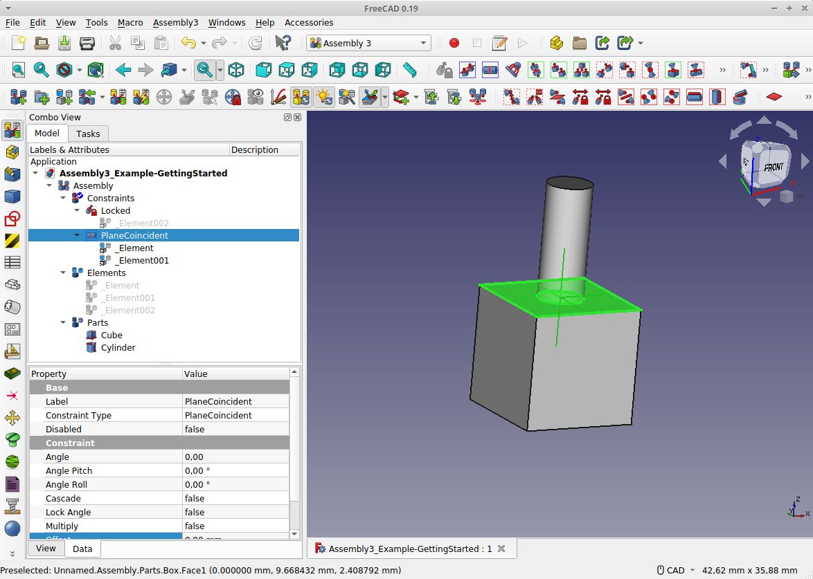
- Final Result of the Getting Started Example. In the image the Assembly3 Workbench is selected, so its multiple toolbars are visible. Note that the vertical "TabBar" left of the tree view is an AddOn Workbench that is not contained in standard FreeCAD (but can be installed with the Addon-Manager).

- Press
 New to create a new FreeCAD file
 - Change to Assembly3 workbench
- Select Create assembly
- Change to
 Part workbench and add a
  Cylinder and a
  Cube
Cube  Save the file with any filename you like.
  Close and
  Open... the file again
The tree view should look like this (0.20.pre and Link Branch):


- Now Drag&Drop with the mouse both Cylinder and Cube onto the Parts folder. They are moved into that folder.
- That is the quickest way and suitable for simple cases like this. A better way is via the use of link objects:
- Select Cube and Cylinder and then
 Make link either from the Context menu (-> LinkActions -> MakeLink) or the Structure panel.
 - This adds two link objects. Then Drag&Drop the link objects to the Parts folder.
- Click both top surfaces of Cylinder and Cube (keep Ctrl pressed (Cmd on a Mac))
- Change to Assembly3 workbench
- Select Plane Coincidence from the Main constraints toolbar.
Now the parts should be joined into each other and your tree should look like this (0.20.pre and Link Branch):


- Right click _Element (either of the two) and select Flip Part.
Now the Cylinder should be on top of the Cube. If the whole thing is upside down, go back and select Flip Part on the other element.
- We omitted one important step that should be done in larger assemblies: Locking a base part.
- That means to define one part that should not be moved by constraints. In this example we use the Cube for that:
- Select the lower face of the Cube. Only the lower face, not the whole Cube
- select the Locked constraint from the Main constraints toolbar
Done.
The finished assembly tree should look like (0.20.pre and Link Branch):

 :
:
If you like you can move the Locked constraint upwards in the tree. Use the ![]() Move item up button on the Main toolbar for that.
Move item up button on the Main toolbar for that.
Note: all new external files must be saved, closed and re-opened at least once, so that Assembly3 can find it.
- Without doing that FreeCAD can not give a file handle to the Assembly3 Workbench and it can not find the new part.
- When all parts are in the same file, you should save, close and re-open this file, too.
Add an Offset
Assembly3 does not offer Offset with the constaints in the way the A2plus Workbench or other CAD tools do. Instead it offers a more general and flexible system to add offsets translations but also angles.
- Add the offset in the properties of one Elements of a Constraint.
- you can choose which one of the two you want to use.
Example:
- Add 2 cubes to an assembly and select their side faces.
- select "PlaneCoincident". The cubes will be attached inside each other.
- select one Element and ContextMenu/Flip Part. The cubes will be attached side-by-side.
- select one Element property Offset/Position/Zz and set to 5mm. The cubes will be 5mm apart.
- Test with other axes or the angle/axis fields. Also verify that you get the same result when using the other Element.
This is the same approach for all other constraints.
Solve a Solver Failure
This often happens when parts are over-constrained, i.e. more than 6 DOF are locked.
The easiest way to find the problem is to click relevant constraints in the tree and select ContextMenu/Disable and re-calculate. It is helpful to know the last added constraints before the solver failed and just undo them.
Note: as Assembly3 tries to compensate for over-constraint parts behind the scenes, sometimes the problem is just triggered by a new constraint but the root cause is somewhere different. Before deleting all and starting again, remember that you can re-use Elements. If you named them you can identify the required elements and re-build the constraints without using the 3D view at all. See Elements seciton above.
Replace a part or rename a filename
When a part is removed or when a filename changes, the assembly breaks, it can not longer be solved and the solver will issue the message "Inconsistent constraints". The solver marks invalid Elements and Constrains with a question mark in the tree.
One way to solve this is to just delete all invalid constraints and elements, import the new part and redo everything. But there is a better way:
- Rename a file
- Use a file manager and copy the file you want renamed. Then give the new name to the copy.
- Open the copy in FreeCAD. The assembly and the old file should also be open
- Select the old object in the tree and click to change the propery "Linked object" (it does contain the old filename)
- A list dialog will open containing all open parts. It shows the filenames and objects of each part. The old part and object is selected. Locate the renamed part in the tree and select the same object in the new part. Then confim the selection.
- Delete the old part in the tree. Also the file can be deleted now.
- Constraints and elements of te old part became invalid. Open the constraint or Elements list in the tree. Then sequentially
- select each element surface on the new part. An item in the tree will be highliged.
- Take that item and drag&drop it over the old element (either in the element list or in one of the constraints where it was used). That element should become valid.
- Repeat the procedure for the remaining elements. Often a single element is enough to allow Assembly3 to identify the remaining elements of the part automatically.
- If an element was assigned to the wrong surface by accident, just repeat with the correct surface.
- Change the object name in FreeCAD, if desired
- Replace a part with another part
- which is simular enough to the original part that the original constraints still make sense, of course
- Delete the old part in the tree. Also the file can be deleted.
- Constraints and elements of te old part became invalid. Open the constraint or Elements list in the tree.
- Select an element surface on the new part. An item in the tree will be highliged.
- Take that item and drag&drop it over the old element (either in the element list or in one of the constraints where it was used). That element should become valid.
- repeat the procedure for the remaining elements.
- If an element was assigned to the wrong surface by accident, just repeat with the correct surface.
- Change the object name in FreeCAD, if desired
Notes
- They are not as complicated as it may seem here. After 2-3 times they should become second nature and feel really easy to do.
- Its not only usually ways quicker than deleting and re-doing constraints, its also safer because an element could have been used in a parent assembly. Deleting the original would destroy that link, re-assingning would keep it.
- Also this procedure becomes really quick and easy to do if constraints and elements are named. There is no guessing where the surfaces should be dragged&dropped to because the names tell it (see Tips & Tricks).
Tips & Tricks
- Using hierarchical assemblies helps in avoiding solver issues and keeping you model fluid. You can freeze a subassembly with one click and save CPU resources easily (use the context menu in the tree). When loading an assembly Assembly3 does not need to open external files for frozen subassemblies which keeps the tree compact.
- Is very helpful to make it a habit to name the elements and constraints. Use the F2 key to do this quickly in the tree. You will find the tree sorting tools in the main toolbar very useful. An assembly with fully named constraints and elements is very easy to understand for other people or for oneself when looking at an older file.
- Examples for constraint names for a table could be "Align_FrontLegs", "Align_FrameBottom-LegTops" and element names could be "Leg1_Top" or "TableTop_Front", "TableTop_Left".
- Please note that once external files are opened by an assembly its not possible easy to close them again without closing the assembly. Since the assembly keeps open those files in the backgound, the tab may disappear but the file remains visible in the tree. If you have several layers of subassemblies it becomes close to impossible to close single files. This behaviour may change, but until then a possible approach could be to regulary use the commands File/Save All and File/Close All to clean up the tree before working on another sub-assembly.
- Example: consider you have a large CNC machine with a main assembly and a subassembly for each module. Once you have the main assembly open it may open literally hundreds of files down to a single ball bearing. Before working on the subassembly of the electronics cabinet of the machine it is a good idea to save and close all files to get an empty tree. Then open just the subassembly for the electronics cabinet. This will open all file it needs but ony those.
- Using external files makes it easier to re-use a parts or do part versioning with systems like git or subversion. The workflow in FreeCAD with Assembly feels quite the same as with files that have all parts in the same file. For exchanging files often with other parties, single files might be more convenient.
- Multiply linked parts. If you added a link into the assembly, it will have a property value named "Element Count", default 0. If you set this to 3 you get 3 instances of that part. They will be added into a subfolder and can be used like fully separte parts. Use this feature to keep the data footprint of your file low, because the part is saved only once. Each instance only contain the differences.
- Insert multiple parts, e.g. Screws, with one click. Check out the Assembly3 Wiki on the Github site. This is not only a stunning function (even a bit magic), but really really useful.
- Using the TabBar Workbench speeds up working with assembly. This adds a Toolbar with one button for each workbench. You can sort the toolbar and can put it where every you want it. Many people put it vertically on the left side just beside the tree view. Of you have Assembly3, Part, PartDesign and other often used workbenches close to the top switching between them becomes extremely easy.
Links
- App Link object that makes Assembly3 work.
- FreeCAD_assembly3 repository and documentation.
- Assembly3 preview, big discussion thread.
- Tutorial for Assembly 3 Workbench by jpg87.
- Tutorials about kinematic assembly, kinematic skeleton, and matching kinematic controller.
- Current Assembly Status
- Addons
- Getting started
- Installation: Download, Windows, Linux, Mac, Additional components, Docker, AppImage, Ubuntu Snap
- Basics: About FreeCAD, Interface, Mouse navigation, Selection methods, Object name, Preferences, Workbenches, Document structure, Properties, Help FreeCAD, Donate
- Help: Tutorials, Video tutorials
- Workbenches: Std Base, Assembly, BIM, CAM, Draft, FEM, Inspection, Material, Mesh, OpenSCAD, Part, PartDesign, Points, Reverse Engineering, Robot, Sketcher, Spreadsheet, Surface, TechDraw, Test Framework
- Hubs: User hub, Power users hub, Developer hub