Tutorial KinematicSkeleton
| Topic |
|---|
| Assembly3, a kinematic skeleton |
| Level |
| Basic knowledge of Assembly3 and Sketcher tools is helpful |
| Time to complete |
| 40 minutes |
| Authors |
| FBXL5 |
| FreeCAD version |
| 0.20 and later |
| Example files |
| None |
| See also |
| Tutorial KinematicAssembly, Tutorial KinematicController |
Introduction
This tutorial is about how to set up a simple 2D mechanism and attach 3D objects, mainly with the tools from the external ![]() Assembly3 Workbench.
Assembly3 Workbench.
This tutorial does not use the skeleton sketch principle (see Assembly3 Create-Skeleton-Sketch on GitHub).
Instead we will use ![]() PartDesign Bodies containing only one
PartDesign Bodies containing only one ![]() Sketch each, to build a 2D mechanism, a multi sketch skeleton.
Sketch each, to build a 2D mechanism, a multi sketch skeleton.
The dimensions, and the colours as well, are taken from the SolveSpace tutorial which is referred to on the Assembly3 GitHub page (see above).
Multi sketch skeleton
This so-called multi sketch skeleton consists of several individual ![]() Bodies and an
Bodies and an ![]() Assembly container. To be able to attach further objects each body is put into a separate Assembly container.
Assembly container. To be able to attach further objects each body is put into a separate Assembly container.
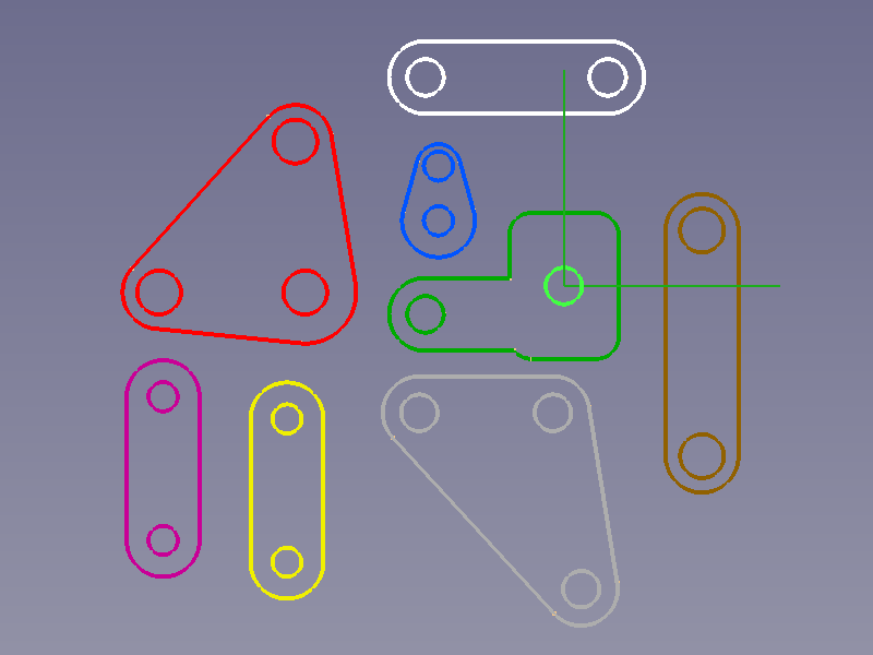
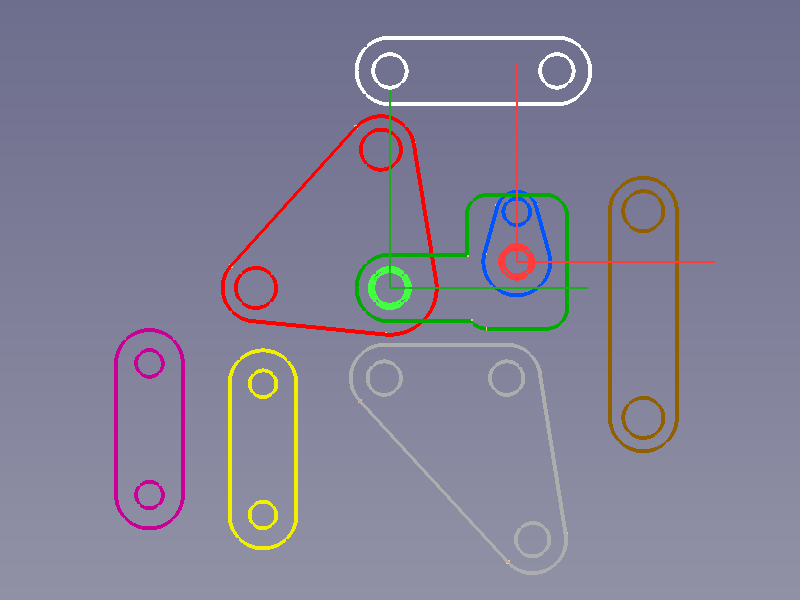
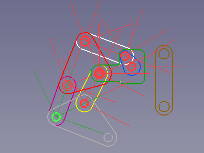
2D Body objects
The bodies, and their sketches, that are used in this assembly:
- A base plate (green)
- A crank (blue)
- Two movable plates (red and grey)
- Four connecting rods (white, yellow, purple, and brown)
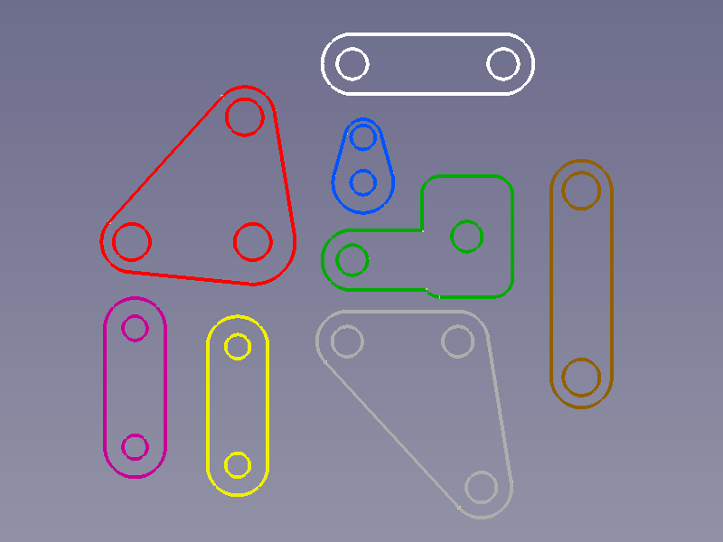
All eight sketches individually coloured and manually positioned by moving their parent bodies
The shape can deviate from that of the real part, but the position of the joint defining geometry must be accurate.
Assembly containers
Parent assembly
To fix or control the positions of all bodies we need an ![]() Assembly object. It adds an assembly branch to the Tree view.
Assembly object. It adds an assembly branch to the Tree view.
- Press the
 Create assembly button to create an assembly branch in the Tree view.
Sub-assemblies
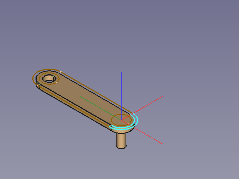
Repeat above action to create an Assembly object for each Body and drag the Body into its Parts container. Then fix the Body to its Assembly:
- Activate the Assembly object (double-click).
- Select a circle/arc belonging the Body object.
- Press the
 Create "Locked" constraint button to fix the Body in its sub-assembly.
The Crank-Assembly, for example, should look like this:
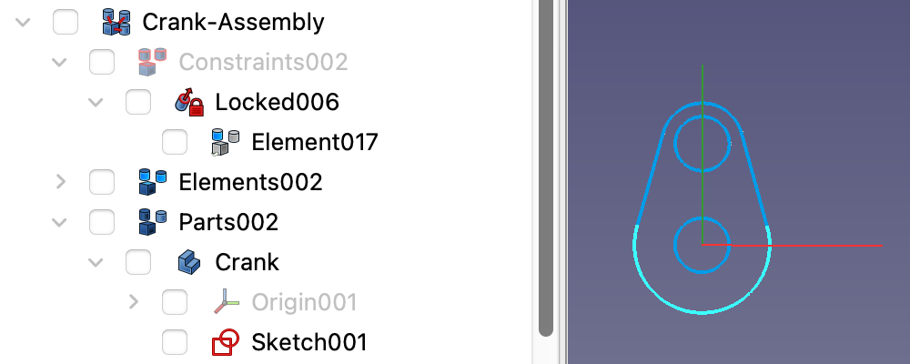
The Crank's sub-assembly branch in the Tree view and the Crank with its locked Element in the 3D view
Assembly tree
In the Tree view drag all sub-assembly branches into the Parts container of the parent Assembly object.
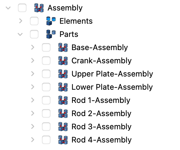
Assembly branch in the Tree view
Now they are ready to be arranged.
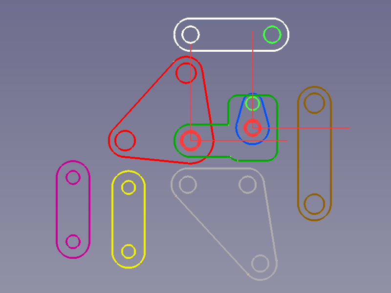
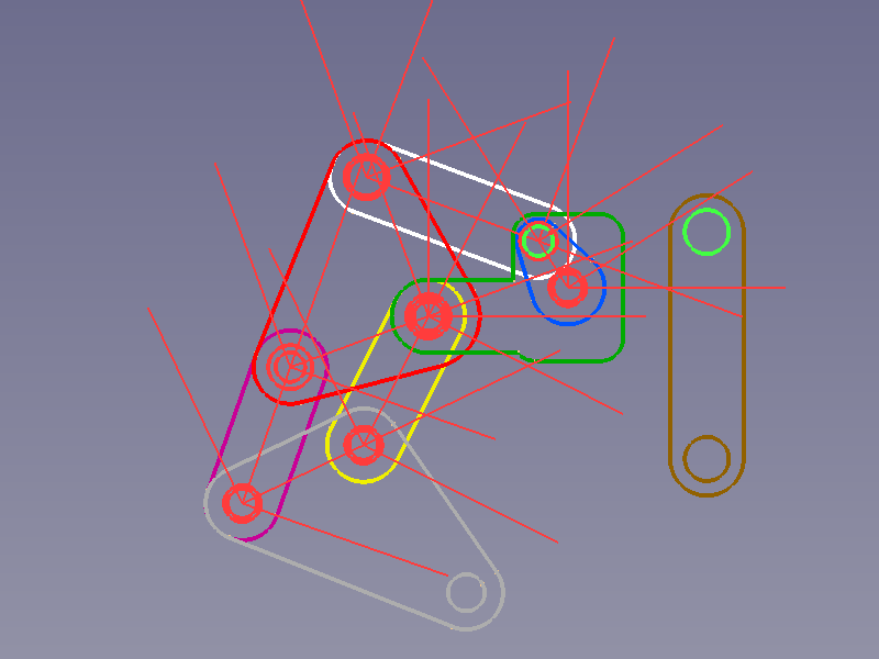
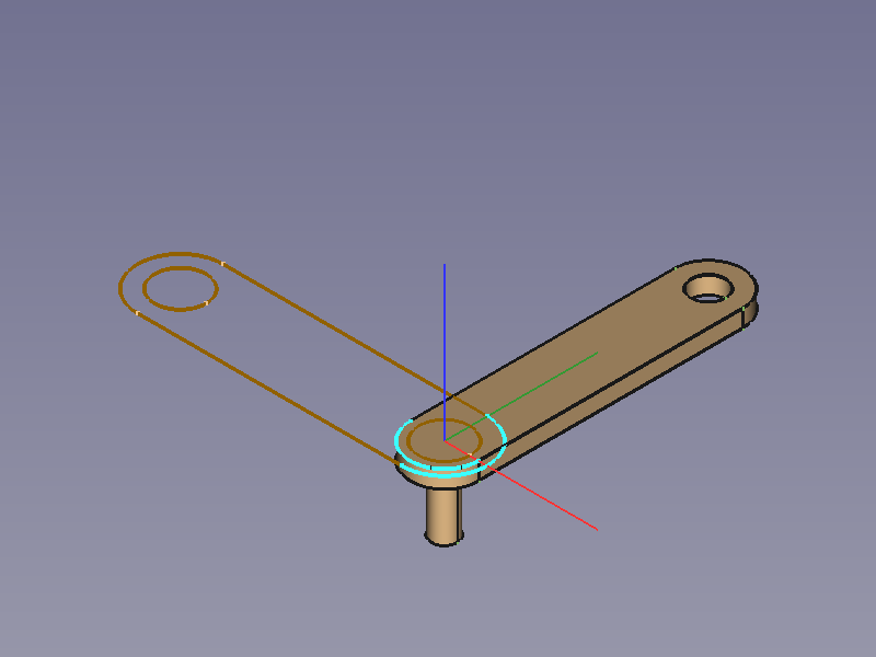
Fixed base plate
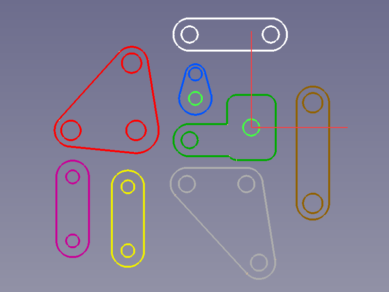
First we need a fixed part. To fix the Base completely we would usually select a face, but in this case a circle will do as well.
- Select a circle of the Base.
- Press the Create "Locked" constraint button to fix the Base.
![]()
Selected circle → Fixed Base with the created Element object and element coordinate system (ECS) displayed (green)
Joints
For hinge-like joints we select one circle of each sketch and use the ![]() Plane Coincidence constraint. It not only sets both Element's XY planes coplanar, but sets their Z axes colinear, too.
Plane Coincidence constraint. It not only sets both Element's XY planes coplanar, but sets their Z axes colinear, too.
- Select a circle of each object to connect.
- Press the
 Create "Plane Coincidence" constraint button.
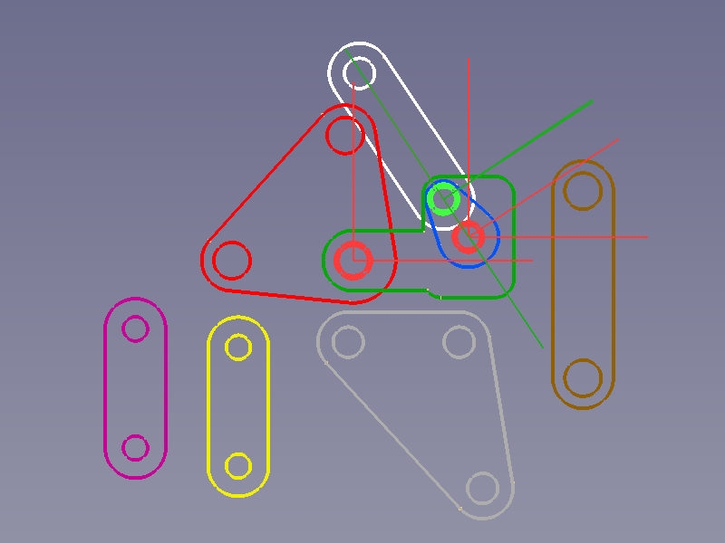
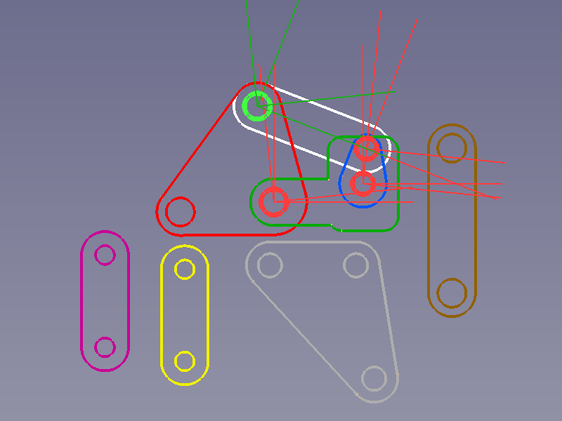
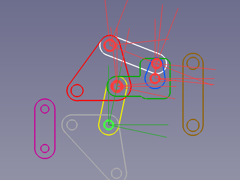
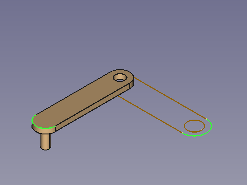
Base - Crank
![]()
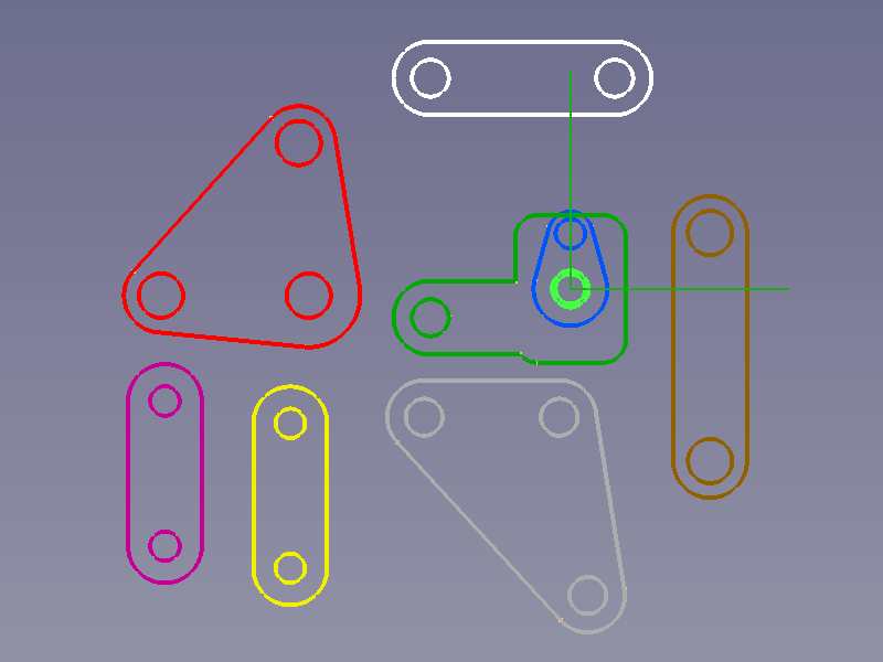
Circles on Base and Crank selected → Relocated Crank with the created Element objects and ECSs displayed (green)
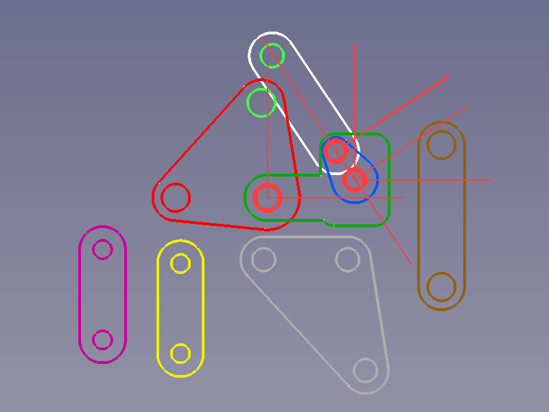
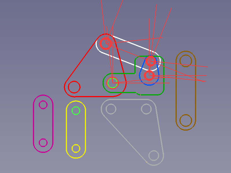
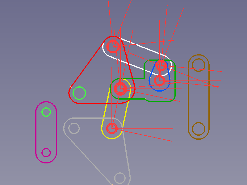
Base - Upper Plate
![]()
Circles on Base and Upper Plate selected → Relocated Upper Plate
Previously created joints can be identified by their constraint representations (red).
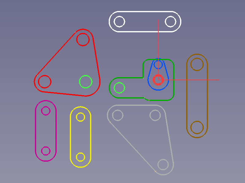
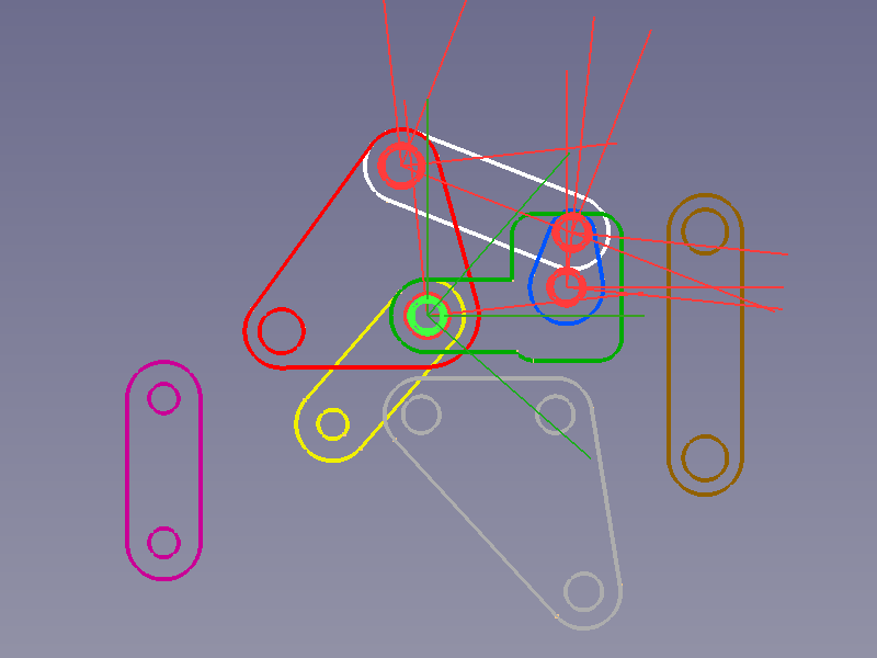
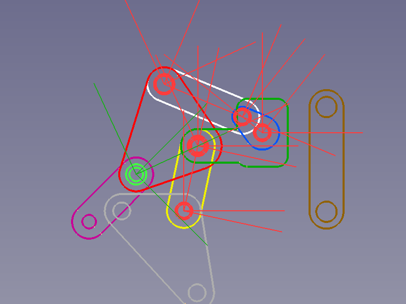
Crank - Rod 1
![]()
Circles on Crank and Rod 1 selected → Relocated Rod 1 and tilted Crank
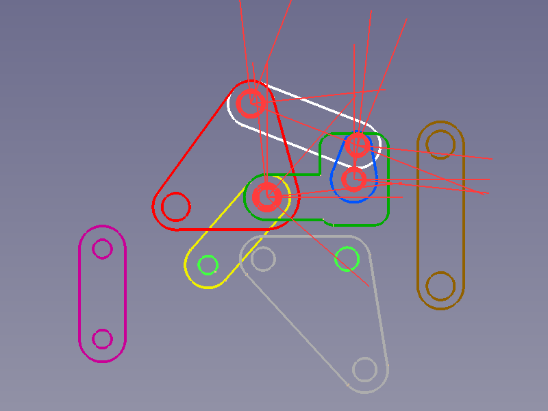
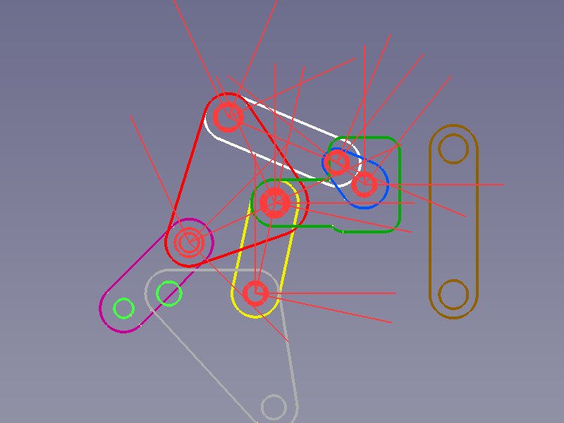
Upper Plate - Rod 1
The last link in this kinematic chain connects two Elements whose Z directions are already defined and a ![]() Point on line constraint is all we need.
Point on line constraint is all we need.
- Select a circle of each object to connect.
- Press the
 Create "PointOnLine" constraint button.
![]()
Circles on Upper Plate and Rod 1 selected → Relocated Rod 1, and tilted Crank and Upper Plate
If the Z axes of three elements or joints are parallel and lie on the same virtual plane, the solver may fail to rearrange them in a following step because it is unable to decide in which direction the middle joint should be rotated. This can occur for the Rod 1 element, the Crank - Rod 1 joint, and the Base - Crank joint we have here. If this happens we need to help the solver and rotate one object (e.g. the Crank) manually using the ![]() Axial move tool.
Axial move tool.
Upper Plate - Rod 2
Another kinematic (sub-)chain starts with ![]() Plane Coincidence constraints.
Plane Coincidence constraints.
![]()
Circles on Upper Plate (or Base) and Rod 2 selected → Relocated Rod 2
Rod 2 - Lower Plate
![]()
Circles on Rod 2 and Lower Plate selected → Relocated Lower Plate and tilted Rod 2
Upper Plate - Rod 3
![]()
Circles on Upper Plate and Rod 3 selected → Relocated Rod 3 and rearranged upper kinematic sub-chain
Lower Plate - Rod 3
And this kinematic (sub-)chain ends with a ![]() Point on line constraint, too.
Point on line constraint, too.
![]()
Circles on Lower Plate and Rod 3 selected → Relocated Rod 3 and rearranged ukinematic sub-chains
To connect both kinematic sub-chains we use Rod 4 with a ![]() Plane Coincidence constraint on one end and a
Plane Coincidence constraint on one end and a ![]() Point on line constraint on the other.
Point on line constraint on the other.
Crank - Rod 4
![]()
Circles on Crank and Rod 4 selected → Relocated Rod 4
Lower Plate - Rod 4
![]()
Circles on Lower Plate and Rod 4 selected → Relocated Rod 4 and final layout of kinematic assembly
Actuator
Since Assembly3 doesn't provide any means to control kinematic assemblies, we need external assistance such as this kinematic controller. To use this controller we need to mark one constraint's label with the suffix "Driver" to make it a driving constraint. It may be separated by a "." or "-" for clarity, as the controller will only check if the label ends with "Driver".
We therefore change the label of the Base-Crank joint to Base-Crank.Driver.
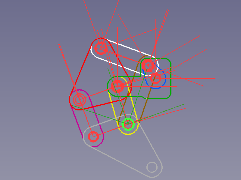
Finished skeleton
The finished kinematic assembly with deactivated representation of Elements and Constraints should look like this:
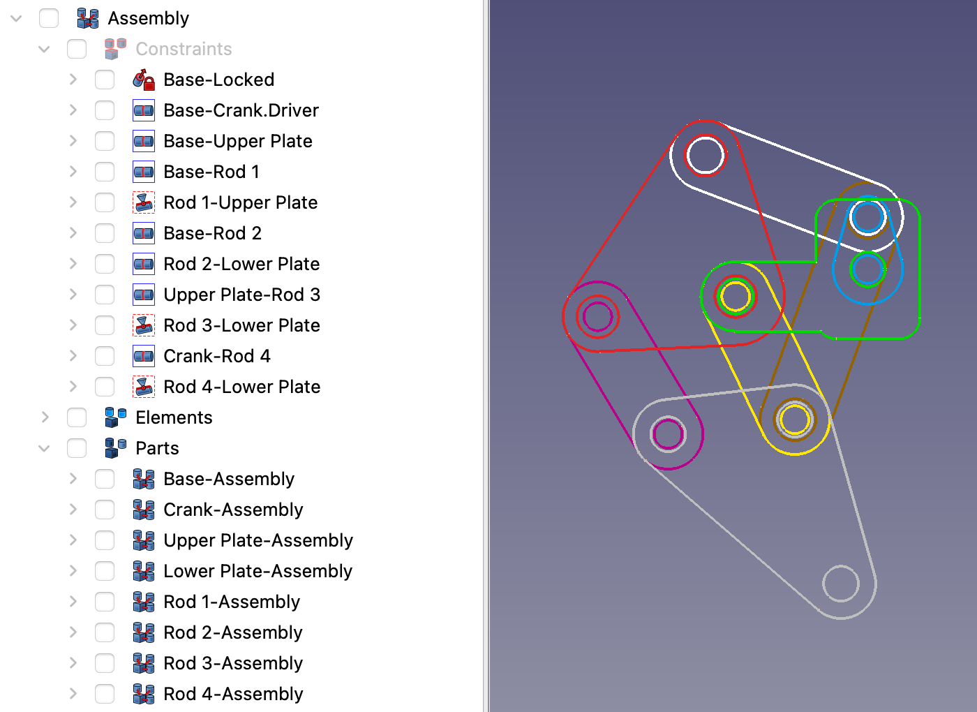
Finished assembly in the Tree view and the 3D view
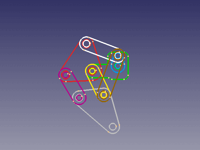
GIF animation made from an image sequence from this kinematic controller
Attaching 3D geometry
My expectations about attaching a new object to a base object belonging to a kinematic assembly were something like:
- Put the new object into the base object's Parts container.
- Position the new object in relation to the base object.
- Fix the relative offset and orientation using the Attachment constraint.
But that would have been too easy.
The ![]() Assembly3 ConstraintAttachment tool, like any Assembly3 constraint tool, relies on the use of Element objects and their element coordinate systems (ECSs) for positioning tasks.
Assembly3 ConstraintAttachment tool, like any Assembly3 constraint tool, relies on the use of Element objects and their element coordinate systems (ECSs) for positioning tasks.
And so attaching objects is just another way of adding objects to a (sub-)assembly.
Let's attach Rod 4-3D to Rod 4 for example:
The objects have a different orientation and the 3D object should have an offset from the 2D object.
- Put the new object into the base object's Parts container.
- Select two corresponding circles or arcs.
- Press the
 Create "Attachment" constraint button.
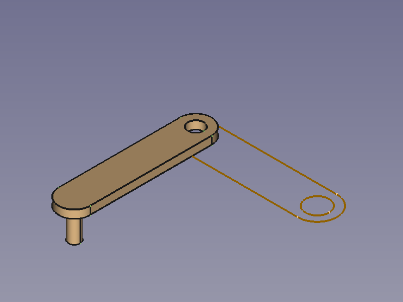
Rod 4 (locked) and Rod 4-3D → Selected arcs → Relocated Rod 4-3D (both ECSs are in the same place with identical orientation)
It is now plain to see that the ![]() Assembly3 ConstraintAttachment tool ignores the offset and orientation between both objects.
Assembly3 ConstraintAttachment tool ignores the offset and orientation between both objects.
However the position is already defined as we wanted and so we only need to adapt the angle manually and define the desired offset:
- Set the DataOffset, Angle of the first Element in the Attachment container to match the orientation.
- Set the DataOffset, Position, z of the same Element to apply an offset.
In case we set the properties of the second Element, the movement of angle and offset would go in the opposite direction.
As attached → Angle adapted → Offset defined
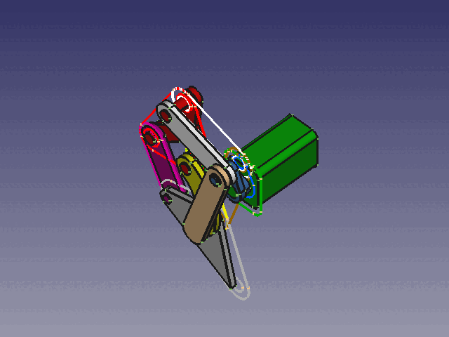
If there is a 3D object attached to each 2D object, it could look like this:
Notes
The section Attaching 3D geometry just scratches the surface of extending a sub-assembly, and other constraints or combinations of constraints may be more suitable than the attachment constraint.
It is important to move such a kinematic assembly in tiny steps or the solver will give up and fail. It is almost impossible to use ![]() Move part or
Move part or ![]() Axial move for this task.
Axial move for this task.
The ![]() Assembly3_ConstraintCoincidence constraint is used to drive the kinematic assembly, its property DataAngle (enabled by the property DataLock Angle) accepts positive or negative floating point numbers greater than 360 and so could do several full turns.
Assembly3_ConstraintCoincidence constraint is used to drive the kinematic assembly, its property DataAngle (enabled by the property DataLock Angle) accepts positive or negative floating point numbers greater than 360 and so could do several full turns.