Feature editing/ru
Введение
На этой странице объясняется, как использовать Верстак PartDesign, начиная с версии FreeCAD 0.17.
Твёрдое тело
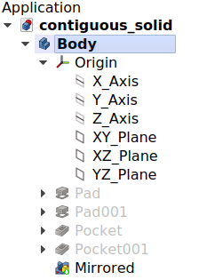
Работа в верстаке PartDesign, начинается с добавления Тела. Тело в PartDesign это контейнер, хранящий в себе последовательность добавления конструктивных элементов, совокупность которых формирует единое твёрдое тело.
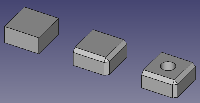
Feature editing in practice. From left to right:
Body with a box feature.
Body with a box and a chamfer feature.
Body with a box, a chamfer and a pocket feature.
A document can contain multiple Bodies, but only one Body can be active. New features are added to the active Body. A Body can be activated or deactivated by double clicking it in the Tree view. The activate Body is highlighted in the Tree view.
What is a contiguous solid?
Что подразумевается под единым твердым телом? Можно сказать, что это предмет изготовленный в процессе наращивания или вырезания материала из металлической заготовки. Если предмет включает в себя гвозди, винты, клей или пайку, это уже не единое твёрдое тело. Например, деревянный стул изготавливается из нескольких тел, по одному для каждого из компонентов (ножки, планки, сиденья и так далее).
В FreeCAD версии 1.0 было введено экспериментальное свойство, которое позволяет телу иметь несмежные твердые тела. Это также можно установить в Preferences по умолчанию для вновь создаваемых тел. Это не предназначено для создания, как в примере, стула в одном корпусе. Это предназначено для того, чтобы элементы, которые могут создавать несвязанные твердые тела, были соединены более поздними элементами.
Когда модель требует несколько тел, как в предыдущем примере деревянного стула, может быть использован Part container общего назначения для их группировки и совместного их перемещения как единого целого.
Body visibility management
По умолчанию тело (Body) представляется извне самым последним элементом. Этот элемент определяется по умолчанию как верхушка. Хорошая аналогия - выражение верхушка айсберга: только верхушка видна над водой, большая часть объёма айсберга (остальные элементы) скрыты. Когда новые feature добавляются к телу, видимость предыдущих отключается, и верхушкой становятся новые.
Только одна feature может быть видима одновременно. Возможно переключение видимости любой feature в теле, выбрав её в древе Модели и нажав пробел, получив в результате откат в истории создания тела.
Перемещение и реорганизация объектов
Элементы объекта могут быть переупорядочены или перемещены в другое тело. Выберите объект и щелкните правой кнопкой мыши, чтобы открыть контекстное меню, предлагающее оба варианта. Операция может быть заблокирована, если объект имеет зависимости от исходного тела, например, привязан к грани. Чтобы переместить эскиз в другое тело, он не должен содержать ссылок на внешнюю геометрию.
Schematic representation of the PartDesign workflow.
Опорная геометрия
Базовая геометрия состоит из пользовательских плоскостей, линий, точек или связанных между собой фигур. Они могут быть созданы для использования в качестве справочных данных в эскизах и конструктивных элементах. Существует множество вариантов вложение для базовых объектов.
Во FreeCAD опорные плоскости имеют смысл, если вы размещаете эскизы в нестандартной ориентации, то есть на плоскостях, смещенных или повернутых вокруг трех основных осей. Но поскольку эскизы также могут быть размещены в нестандартной ориентации и иметь те же возможности крепления, что и базовые плоскости, в их использовании часто нет необходимости. Базовые плоскости наиболее целесообразны, если имеется несколько эскизов с одинаковой нестандартной ориентацией. Корректировка ориентации базовой плоскости затем приведет к корректировке всех связанных эскизов и объектов, созданных на основе этих эскизов.
Хотя в FreeCAD версии 1.0 уже есть код для устранения проблемы топологическое именование, по-прежнему рекомендуется по возможности привязывать как эскизы, так и опорные плоскости к базовым плоскостям начала координат объекта. Использование сгенерированной геометрии (геометрии, которая является результатом работы с элементом, например, накладкой или карманом) может привести к созданию менее стабильных моделей. Смотрите Советы по созданию стабильных моделей ниже.
Советы для создания стабильных моделей
The idea of parametric modeling implies that you can change the values of certain parameters and subsequent steps are changed according to the new values. However, when severe changes are made, the model can break due to the topological naming problem. Breakage can be minimized if you respect the following design principles:
- Avoid attaching sketches and custom datum geometry to generated geometry, that is any face, edge or vertex, of the model's solid. Attach them to the standard planes/axes of the Origin of the Body instead. Sketches attached to standard planes/axes or to datum geometry attached to standard planes/axes, will not get unexpectedly reattached to a different reference. Use attachment offsets as needed.
- Use a "master sketch". Since a master sketch is done before the rest of the model, it can only reference the standard planes/axes.
- A master sketch should be as simple as possible, containing the basic geometric elements of your model.
- Master sketch elements can be referenced when modelling subsequent features.
- A master sketch can be the first sketch in the Body, or outside the Body completely. In the first case it can be referenced directly as external geometry, in the latter it can be referenced via a
ShapeBinder or
SubShapeBinder.
- Don't create (Sub)ShapeBinders from generated geometry. Keep in mind that (Sub)ShapeBinders can be an issue if geometry is deleted from the sketch it is based on.
- Always first try to reference a sketch, or sketch geometry, rather than generated geometry. If you inevitably have to reference generated geometry, use the first feature where the element to be referenced occurs. Changes to later steps then won't break your model.
- Use dress ups, like fillets and chamfers, as late in the feature tree as possible.
Материалы для самостоятельного изучения
The tutorials page provides some examples of using the feature editing method of the PartDesign Workbench.
Сопутствующая информация
- Инструменты структуры: Part, Group
- Вспомогательные инструменты: Create body, Create sketch, Edit sketch, Map sketch to face
- Инструменты моделирования
- Инструменты данных: Create a datum point, Create a datum line, Create a datum plane, Create a local coordinate system, Create a shape binder, Create a clone
- Аддитивные инструменты: Pad, Revolution, Additive loft, Additive pipe, Additive box, Additive cone, Additive cylinder, Additive ellipsoid, Additive prism, Additive sphere, Additive torus, Additive wedge
- Субстрактивные инструменты: Pocket, Hole, Groove, Subtractive loft, Subtractive pipe, Subtractive box, Subtractive cone, Subtractive cylinder, Subtractive ellipsoid, Subtractive prism, Subtractive sphere, Subtractive torus, Subtractive wedge
- Инструменты трансформации: Mirrored, Linear Pattern, Polar Pattern, Create MultiTransform
- Отделочные инструменты: Fillet, Chamfer, Draft, Thickness
- Бинарные: Boolean operation
- Дополнительно: Migrate, Shaft design wizard, Involute gear
- Инструменты контекстного меню: Set tip, Move object to other body, Move object after other object
- Начинающим
- Установка: Загрузка, Windows, Linux, Mac, Дополнительных компонентов, Docker, AppImage, Ubuntu Snap
- Базовая: О FreeCAD, Интерфейс, Навигация мыши, Методы выделения, Имя объекта, Настройки, Верстаки, Структура документа, Свойства, Помоги FreeCAD, Пожертвования
- Помощь: Учебники, Видео учебники
- Верстаки: Std Base, Arch, Assembly, CAM, Draft, FEM, Inspection, Mesh, OpenSCAD, Part, PartDesign, Points, Reverse Engineering, Robot, Sketcher, Spreadsheet, Surface, TechDraw, Test Framework

