PartDesign SubShapeBinder
|
|
| Menu location |
|---|
| Part Design → Sub-Shape Binder |
| Workbenches |
| PartDesign |
| Default shortcut |
| None |
| Introduced in version |
| 0.19 |
| See also |
| PartDesign ShapeBinder, PartDesign Clone |
Description
The PartDesign SubShapeBinder tool creates a shape binder referencing geometry from one or more parent objects. A SubShapeBinder is typically used inside a PartDesign Body to reference geometry outside the Body. Using external geometry directly in a Body is not allowed and will lead to out of scope errors. But a SubShapeBinder can also be used without being nested in a Body.
A SubShapeBinder will track the relative placement of the referenced geometry, which is useful in the context of creating assemblies, but on top of that also has its own placement.
The referenced geometry can consist of one or multiple elements. Each element can be an individual object (for example a PartDesign Body), a subobject (for example a Part Box inside a Std Part, or a sketch or Feature inside a Body), or a subelement (a face, edge or vertex). Which geometry should be selected depends on the intended purpose of the SubShapeBinder. For a Boolean operation you would need to select a solid. For a Pad operation a face, a sketch or a planar wire can be used. And for the external geometry in a sketch, or to attach a sketch, any combination of subelements may be appropriate. Elements can belong to different parent objects, and can even belong to the Body the SubShapeBinder is nested in. Because a SubShapeBinder is Link-based the referenced geometry can also belong to an external document.
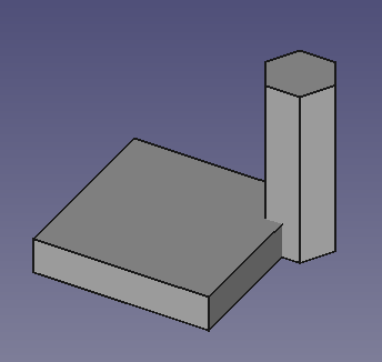
On the left two solids created in two separate Bodies.
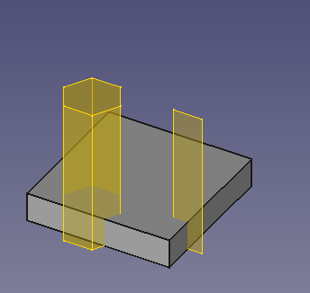
On the right two SubShapeBinders referencing geometry from the first Body, nested in the second Body, and moved to a different position.
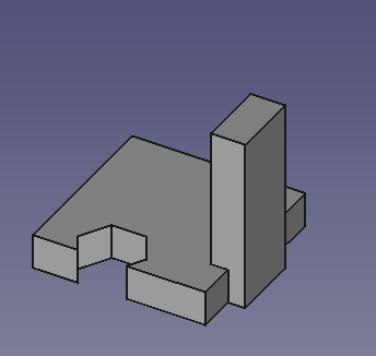
The two SubShapeBinders are used to create a Boolean cut and a Pad in the second Body.
Usage
Same document
- If there are multiple Bodies in the document: optionally activate the Body the SubShapeBinder should be nested in.
- Select the required geometry. Subelements can only be selected in the 3D View.
- There are several ways to invoke the tool:
- Press the
Sub-Shape Binder button.
- Select the Part Design →
Sub-Shape Binder option from the menu.
- Press the
- The SubShapeBinder is created.
- If there is only one Body in the document the SubShapeBinder is automatically added to it and the Body is activated. If this is the case and the SubShapeBinder should not be nested, it can be dragged out of the Body and dropped onto the
document node in the Tree View.
External document
- If required open the source document (the external document) and the target document. Both documents must have been saved at least once.
- If there are multiple Bodies in the target document: optionally activate the Body the SubShapeBinder should be nested in.
- Select the required geometry in the source document. Subelements can only be selected in the 3D View.
- Switch to the target document by clicking its tab in the Main View Area.
- Invoke the tool as described above.
Start with empty SubShapeBinder
- Follow the instructions described under Same document above but without selecting geometry.
- An empty SubShapeBinder is created.
- Select the required geometry. Subelements can only be selected in the 3D View.
- In the Tree View drag and drop the selection onto the SubShapeBinder. If you have selected subelements their parent objects are highlighted in the Tree View, indicating the objects to be dragged.
- Optionally add more geometry in the same manner.
- To replace already referenced geometry hold down Ctrl during the drag and drop operation.
Notes
- 2D offsetting is supported for some shape types, included planar faces, edges and wires. Because offsetting is a difficult operation for the software it does not always succeed.
- A SubShapeBinder that is not nested in a Body can be used as the Base Feature for a new Body.
- The DataSupport property contains the links to the referenced geometry. The property is read only by default, but can be changed by following the instructions described under Start with empty SubShapeBinder.
- A SubShapeBinder created from a sketch can have an opposite "tool direction". For example a Pad created from the sketch may extend in the +Y direction, while a Pad, with the same properties, created from the SubShapeBinder extends in the -Y direction. Toggling the DataReversed property (or checkbox) will solve this.
PartDesign SubShapeBinder vs. PartDesign ShapeBinder
Properties
A PartDesign SubShapeBinder object is derived from a Part Feature object and inherits all its properties. It also has the following additional properties:
Data
Base
- DataSupport (
XLinkSubList): support for the geometry. - DataFuse (
Bool): if it istrueit will fuse the solid linked shapes. - DataMake Face (
Bool): if it istrueit will created a face for the linked wires. - DataClaim Children (
PropertyBool): if it istrueit will claim the linked objects as children in the Tree View. - DataRelative (
Bool): if it istrueit will enable relative sub-object linking. - DataBind Mode (
Enumeration): binding mode,Synchronized,Frozen,Detached. - DataPartial Load (
Bool): if it istrueit will enable partial loading of the objects. - Data (hidden)Context (
XLink): container object of this binder object. - DataBind Copy On Change (
Enumeration) - DataRefine (
Bool): iftrueredundant edges will be removed (for example after a boolean operation). - Data (hidden)_ Version (
Integer): version of this type of object. - Data (hidden)_ Copied Link (
XLinkSub)
Cache
- Data (hidden)Cache_* (
Matrix): unity matrix (separate property for each object in DataSupport).
Offsetting
- DataOffset: 2D offset to apply. If Offset = 0, then no offset is applied. If Offset < 0, then the offset is applied inward.
- DataOffset Join Type: Join method of offsetting non-tangent joints. The method can be
Arcs,TangentorIntersection. - DataOffset Fill (
Bool): Iftrue, a face is made between the new wire and the original wire. See also the DataMake Face property. - DataOffset Open Result (
Bool): Affects the way open wires are processed. Iffalse, an open wire is made. Iftrue, a closed wire is made from a double-sided offset, with rounds around open vertices. - DataOffset Intersection (
Bool): Affects the way compounds are processed. Iffalse, all children are processed independently. Iftrue, and children are edges and wires, the children are offset in a collective manner.
View
Base
- ViewUse Binder Style (
Bool): Iftruethe colors of the binder object depend on the fine-tuning parameter DefaultDatumColor. Iffalse, normal shape colors are applied.
Links
- New Sublink Link Feature, usage explanation with video.
- Helper tools: New Body, New Sketch, Attach Sketch, Edit Sketch, Validate Sketch, Check Geometry, Sub-Shape Binder, Clone
- Modeling tools:
- Additive tools: Pad, Revolution, Additive Loft, Additive Pipe, Additive Helix, Additive Box, Additive Cylinder, Additive Sphere, Additive Cone, Additive Ellipsoid, Additive Torus, Additive Prism, Additive Wedge
- Subtractive tools: Pocket, Hole, Groove, Subtractive Loft, Subtractive Pipe, Subtractive Helix, Subtractive Box, Subtractive Cylinder, Subtractive Sphere, Subtractive Cone, Subtractive Ellipsoid, Subtractive Torus, Subtractive Prism, Subtractive Wedge
- Boolean: Boolean Operation
- Dress-up tools: Fillet, Chamfer, Draft, Thickness
- Transformation tools: Mirror, Linear Pattern, Polar Pattern, Multi-Transform, Scale
- Additional tools: Shape Binder, Involute Gear, Sprocket, Shaft Design Wizard
- Context menu: Suppressed, Set Tip, Move Object To…, Move Feature After…
- Preferences: Preferences, Fine tuning
- Getting started
- Installation: Download, Windows, Linux, Mac, Additional components, Docker, AppImage, Ubuntu Snap
- Basics: About FreeCAD, Interface, Mouse navigation, Selection methods, Object name, Preferences, Workbenches, Document structure, Properties, Help FreeCAD, Donate
- Help: Tutorials, Video tutorials
- Workbenches: Std Base, Assembly, BIM, CAM, Draft, FEM, Inspection, Material, Mesh, OpenSCAD, Part, PartDesign, Points, Reverse Engineering, Robot, Sketcher, Spreadsheet, Surface, TechDraw, Test Framework
- Hubs: User hub, Power users hub, Developer hub


