PartDesign SubShapeBinder/it
|
|
| Posizione nel menu |
|---|
| Part Design → Crea un riferimento di forma per i(l) sotto oggetti(o) |
| Ambiente |
| PartDesign |
| Avvio veloce |
| Nessuno |
| Introdotto nella versione |
| 0.19 |
| Vedere anche |
| Creare un clone |
Descrizione
Lo strumento PartDesign SubShapeBinder crea una forma legata che fa riferimento alla geometria da uno o più oggetti principali. Un SubShapeBinder viene in genere utilizzato all'interno di un Corpo per fare riferimento alla geometria esterna al corpo. L'utilizzo della geometria esterna direttamente in un corpo non è consentito e porterà a errori fuori ambito. Ma un SubShapeBinder può essere utilizzato anche senza essere annidato in un Body.
Una Forma Legata Secondaria traccerà il posizionamento relativo della geometria di riferimento, che è utile nel contesto della creazione di assiemi, ma oltre a ciò ha anche un proprio posizionamento.
La geometria referenziata può essere composta da uno o più elementi. Ogni elemento può essere un oggetto individuale (ad esempio un Corpo di PartDesign), un sotto-oggetto (ad esempio un Cubo di Part all'interno di una Parte, o uno schizzo o una Funzione all'interno di un Corpo), o un sotto-elemento (una faccia, un bordo o un vertice). La geometria da selezionare dipende dallo scopo previsto per il SubShapeBinder. Per un'operazione booleana, si dovrebbe selezionare un solido. Per un'operazione di estrusione, è possibile utilizzare una faccia, uno schizzo o un bordo planare. E per la geometria esterna in uno schizzo, o per collegarsi a uno schizzo, può essere appropriata qualsiasi combinazione di sotto-elementi. Gli elementi possono appartenere a diversi oggetti padre e possono persino appartenere al Body in cui è annidato lo SubShapeBinder. Poiché un SubShapeBinder è basato sui link, la geometria referenziata può anche appartenere a un documento esterno.
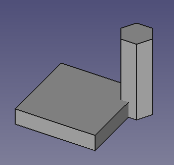
A sinistra: due solidi creati in due Corpi separati.
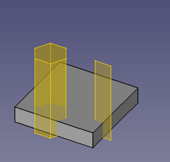
A destra: due SubShapeBinders estratti dal primo corpo, importati nel secondo corpo e spostati in una posizione diversa.
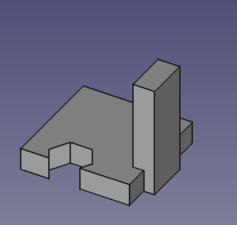
I due SubShapeBinders vengono utilizzati per creare un Taglio booleano e un Pad, con il secondo Corpo.
Utilizzo
Stesso documento
- Se nel documento sono presenti più Corpi: facoltativamente attivare il Corpo in cui verrà inserito il SubShapeBinder.
- Selezionare la geometria richiesta. I sottoelementi possono essere selezionati solo nella vista 3D.
- Esistono diversi modi per richiamare lo strumento:
- Premere il pulsante
Crea un riferimento di forma per i(l) sotto oggetti(o) di PartDesign.
- Selezionare l'opzione Part Design →
Crea un riferimento di forma per i(l) sotto oggetti(o) dal menu.
- Premere il pulsante
- Viene creato il SubShapeBinder.
- Se nel documento è presente un solo Corpo, il SubShapeBinder viene automaticamente aggiunto a questo e il Corpo viene attivato. Se in questo caso il SubShapeBinder non si desidera che sia inserito, può essere trascinato fuori dal Corpo e rilasciato sul nodo del documento
nella Vista ad albero.
Documento esterno
- Se necessario, aprire il documento sorgente (il documento esterno) e il documento di destinazione. Entrambi i documenti devono essere stati salvati almeno una volta.
- Se nel documento di destinazione sono presenti più Corpi: eventualmente attivare il Corpo in cui deve essere annidato il SubShapeBinder.
- Selezionare la geometria richiesta nel documento sorgente. I sottoelementi possono essere selezionati solo nella vista 3D.
- Passare al documento di destinazione cliccando sulla sua scheda nell'Area della vista principale.
- Richiamare lo strumento come descritto sopra.
Iniziare con uno SubShapeBinder vuoto
- Seguire le istruzioni descritte per lo Stesso documento come sopra, ma senza selezionare la geometria.
- Viene creato un SubShapeBinder vuoto.
- Selezionare la geometria richiesta. I sottoelementi possono essere selezionati solo nella vista 3D.
- Nella Vista ad albero trascinare e rilasciare la selezione sullo SubShapeBinder. Se si sono selezionati dei sottoelementi, i loro oggetti padre sono evidenziati nella Vista ad albero, indicando gli oggetti da trascinare.
- Se lo si desidera, aggiungere dell'altra geometria nello stesso modo.
- Per sostituire la geometria già selezionata, tenere premuto Ctrl durante l'operazione di trascinamento.
Note
- L'offset 2D è supportato per alcuni tipi di forma, incluse facce planari, bordi e linee. Poiché l'offset è un'operazione difficile per il software, non sempre riesce.
- Un SubShapeBinder non nidificato in un Corpo può essere utilizzato come Funzione di base per un nuovo Corpo.
- La proprietà DatiSupport contiene i collegamenti alla geometria referenziata. La proprietà è di sola lettura per impostazione predefinita, ma può essere modificata seguendo le istruzioni descritte in Iniziare con uno SubShapeBinder vuoto.
- Uno SubShapeBinder creato da uno schizzo può avere una "direzione utensile" opposta. Ad esempio, una Estrusione creata da uno schizzo può estendersi nella direzione +Y, mentre una Estrusione, con le stesse proprietà, creata dal SubShapeBinder si potrebbe estendere nella direzione -Y. L'attivazione della proprietà (o dalla casella di controllo) DatiReversed dovrebbere risolvere questo problema.
PartDesign SubShapeBinder vs. PartDesign ShapeBinder
Vedere ShapeBinder di PartDesign.
Proprietà
Un oggetto PartDesign SubShapeBinder deriva da un oggetto Funzione Part e ne eredita tutte le proprietà. Ha anche le seguenti proprietà aggiuntive:
Dati
Base
- DatiSupport (
XLinkSubList): supporto per la geometria. - DatiFuse (
Bool): se ètruefonde le forme solide legate. - DatiMake Face (
Bool): se ètruecrea una faccia dalle polilinee connesse. - DatiClaim Children (
PropertyBool): se ètruerichiama gli oggetti collegati come figli nella vista ad albero. - DatiRelative (
Bool): se ètrueabiliterà il collegamento relativo degli oggetti secondari. - DatiBind Mode (
Enumeration): modalità di legame,Synchronized,Frozen,Detached. - DatiPartial Load (
Bool): se ètrueabiliterà il caricamento parziale degli oggetti. - Dati (hidden)Context (
XLink): oggetto contenitore di questo oggetto raccoglitore. - DatiBind Copy On Change (
Enumeration) - DatiRefine (
Bool): setruei bordi in eccesso verranno rimossi (ad esempio dopo un'operazione booleana). - Dati (hidden)_ Version (
Integer): versione di questo tipo di oggetto. - Dati (hidden)_ Copied Link (
XLinkSub)
Cache
- Dati (hidden)Cache_* (
Matrix): matrice di unità (proprietà separata per ogni oggetto in DatiSupport).
Offsetting
- DatiOffset: offset 2D da applicare. Se Offset = 0, non viene applicato alcun offset. Se Offset < 0, l'offset viene applicato verso l'interno.
- DatiOffset Join Type: metodo di giunzione per l'offset di giunti non tangenti. Il metodo può essere
Arcs,TangentoIntersection. - DatiOffset Fill (
Bool): setrue, viene creata una faccia tra la nuova linea e la linea originale. Vedere anche la proprietà DatiMake Face. - DatiOffset Open Result (
Bool): influenza il modo in cui vengono elaborate le linee aperte. Sefalse, viene creato una linea aperta. Setrue, viene creata una linea chiusa da un offset bilaterale, con arrotondamenti attorno ai vertici aperti. - DatiOffset Intersection (
Bool): influenza il modo in cui vengono elaborati i compounds. Sefalse, tutti i figli vengono elaborati in modo indipendente. Setruee i figli sono spigoli e linee, i figli ricevono un offset in modo collettivo.
Vista
Base
- VistaUse Binder Style (
Bool): Setruei colori dell'oggetto collegato dipendono dal parametro di fine-tuning DefaultDatumColor. Sefalse, vengono applicati i colori delle forme normali.
Link
- New Sublink Link Feature, spiegazione sull'uso con video.
- Helper tools: New Body, New Sketch, Attach Sketch, Edit Sketch, Validate Sketch, Check Geometry, Sub-Shape Binder, Clone
- Modeling tools:
- Additive tools: Pad, Revolution, Additive Loft, Additive Pipe, Additive Helix, Additive Box, Additive Cylinder, Additive Sphere, Additive Cone, Additive Ellipsoid, Additive Torus, Additive Prism, Additive Wedge
- Subtractive tools: Pocket, Hole, Groove, Subtractive Loft, Subtractive Pipe, Subtractive Helix, Subtractive Box, Subtractive Cylinder, Subtractive Sphere, Subtractive Cone, Subtractive Ellipsoid, Subtractive Torus, Subtractive Prism, Subtractive Wedge
- Boolean: Boolean Operation
- Dress-up tools: Fillet, Chamfer, Draft, Thickness
- Transformation tools: Mirror, Linear Pattern, Polar Pattern, Multi-Transform, Scale
- Additional tools: Shape Binder, Involute Gear, Sprocket, Shaft Design Wizard
- Context menu: Suppressed, Set Tip, Move Object To…, Move Feature After…
- Preferences: Preferences, Fine tuning
- Getting started
- Installation: Download, Windows, Linux, Mac, Additional components, Docker, AppImage, Ubuntu Snap
- Basics: About FreeCAD, Interface, Mouse navigation, Selection methods, Object name, Preferences, Workbenches, Document structure, Properties, Help FreeCAD, Donate
- Help: Tutorials, Video tutorials
- Workbenches: Std Base, Assembly, BIM, CAM, Draft, FEM, Inspection, Material, Mesh, OpenSCAD, Part, PartDesign, Points, Reverse Engineering, Robot, Sketcher, Spreadsheet, Surface, TechDraw, Test Framework
- Hubs: User hub, Power users hub, Developer hub


