SheetMetal AddBase/it
This documentation is not finished. Please help and contribute documentation.
GuiCommand model explains how commands should be documented. Browse Category:UnfinishedDocu to see more incomplete pages like this one. See Category:Command Reference for all commands.
See WikiPages to learn about editing the wiki pages, and go to Help FreeCAD to learn about other ways in which you can contribute.
|
|
| Menu location |
|---|
| SheetMetal → Make Base Wall |
| Workbenches |
| SheetMetal |
| Default shortcut |
| C B |
| Introduced in version |
| - |
| See also |
| None |
Description
The ![]() SheetMetal AddBase command creates a SheetMetal base object from a sketch.
SheetMetal AddBase command creates a SheetMetal base object from a sketch.
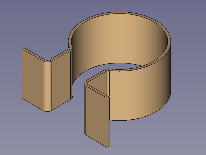
From an open contour it creates a prismatic profile:
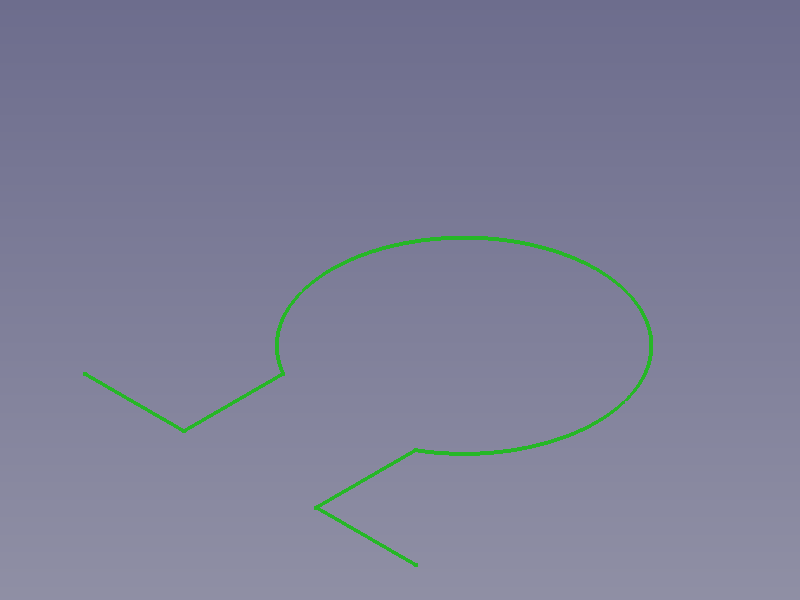
![]()
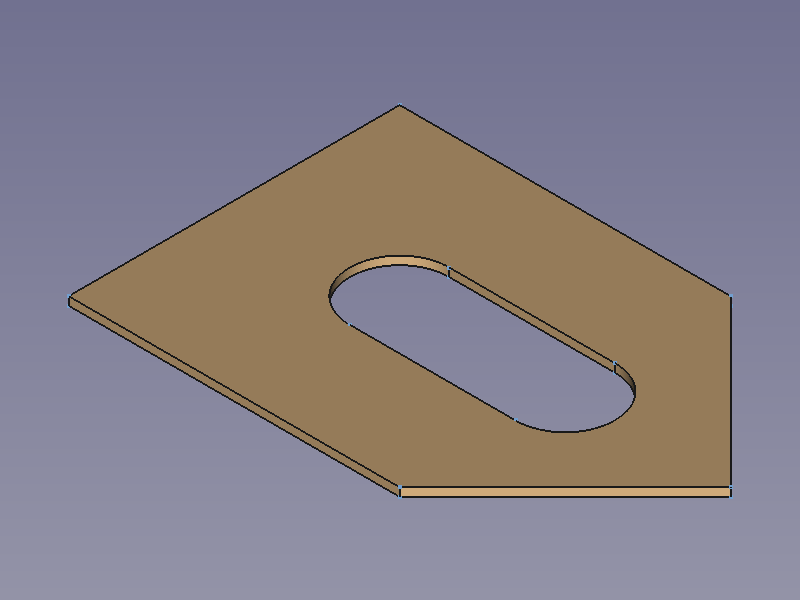
From a closed outline it creates a base plate (blank):
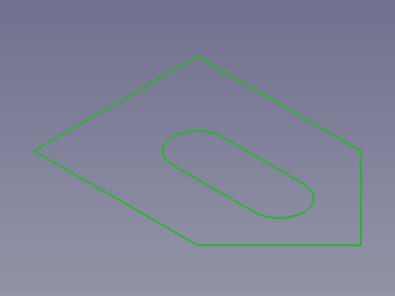
![]()
Usage
Profile
- Select an open contour
 sketch.
 - There are several ways to invoke the command:
- Press the
 Make Base Wall button.
 - Select the Sheet Metal → Make Base Wall option from the menu.
- Right-click in the Tree View or the 3D View and select the Sheet Metal → Make Base Wall option from the context menu.
- Use the keyboard shortcut: C then B.
- Press the
- A BaseBend object is created, corners along the contour are automatically converted into cylindrical bends, and the Sketched base shape properties Task Panel opens:
- Optionally press the Sketch button and select a different sketch.
- Adjust the profile parameters in the Task Panel.
- Press the OK button to close the Task Panel and finish the command.
- Optionally adjust the profile parameters in the Property View.
Plate
- Select a closed outline sketch.
- Invoke the command as described above.
- A BaseBend object is created and the Generate Sheet Metal base shape Task Panel opens:
- Optionally press the Sketch button and select a different sketch.
- Adjust the plate parameters in the Task Panel.
- Press the OK button to close the Task Panel and finish the command.
- Optionally adjust the plate parameters in the Property View.
Task Panel
A task panel was introduced in version 0.6.01
Double-click an existing BaseBend object in the Tree View to re-open the task panel and edit the parameters.

- Sketch: Links a different Sketch to the Bend Sketch property.
- Bend Plane: Sets the Bend Side property.
- Radius: Sets the Radius property.
- Thickness: Sets the Thickness property.
- Length: Sets the Length property.
- Symmetric: Toggles the Mid Plane property.
- Reverse Direction: Toggles the Reverse property. (hidden if Symmetric is checked)
The last entered values for Radius and Thickness will be saved as default values for the following new BaseBend object.
Properties
See also: Property View.
A SheetMetal BaseBend object is derived from a Part Feature object or, if it is inside a PartDesign Body, from a PartDesign Feature object, and inherits all its properties. It also has the following additional properties:
Data
Parameters
- DatiBend Side (
Enumeration): "Bend Plane", defines on which side of a profile curve the thickness applies.Outside(default),Inside,Middle. (not used for plates) - DatiBend Sketch (
Link): "Wall Sketch object". Link to the profile/outline sketch. - DatiLength (
Length): Extrusion length of a profile. Default:100,00 mm. (not used for plates) - DatiMid Plane (
Bool): "Extrude Symmetric to Plane". The length of a profile or the thickness of a plate extends to one side of the sketch plane iffalse(default) or symmetrically to both sides iftrue. - DatiRadius (
Length): Inner radius of automatically added bends. Default:1,00 mm. (not used for plates) - DatiReverse (
Bool): Reverses the direction of a profile extrusion or a plate thickness. Default:false. - DatiThickness (
Length): Wall thickness of a sheetmetal profile or plate. Default:1,00 mm.