SheetMetal AddWall
This documentation is not finished. Please help and contribute documentation.
GuiCommand model explains how commands should be documented. Browse Category:UnfinishedDocu to see more incomplete pages like this one. See Category:Command Reference for all commands.
See WikiPages to learn about editing the wiki pages, and go to Help FreeCAD to learn about other ways in which you can contribute.
|
|
| Menu location |
|---|
| SheetMetal → Make Wall |
| Workbenches |
| SheetMetal |
| Default shortcut |
| W |
| Introduced in version |
| - |
| See also |
| None |
Description
The ![]() SheetMetal AddWall command creates flanges on selected edges. By changing the Dataangle property a flange it can be turned into a hem.
SheetMetal AddWall command creates flanges on selected edges. By changing the Dataangle property a flange it can be turned into a hem.
A flange usually consists of a 90° cylindrical bend and a planar strip (wall).

![]()

Two selected edges → two flanges
It is called a hem instead if the bend is roughly 180°.

![]()

Two selected edges → two mitered hems
Usage
- Select one or more edges of a solid shape.
- There are several ways to invoke the command:
- A Bend object is created that consists of one new flange at each selected edge, and the Flange properties Task Panel opens:
- With the General tab selected:
- Optionally press the Select button to add more edges.
- Optionally press the Clear selection button to clear the list of selected edges (introduced in 0.7.11).
- Press the Preview button to finish the selection and display the changes.
- Optionally adjust the bend parameters in this tab. See the General section of the Task Panel description below
- Optionally press the Select button to add more edges.
- Optionally switch to another tab to adjust more parameters. See Offsets, Miter, or Perforation section of the Task Panel description below.
- With the General tab selected:
- Press the OK button to finish the command and close the Task Panel.
- Optionally adjust the parameters in the Property View.
Task Panel
A Task Panel with four tabs was introduced in 0.6.00
Double-click an existing Bend object in the Tree View to re-open the Task Panel and edit the parameters.
General

- Select: Changes the amount of edges in the base Object property.
- Length: Sets the length property.
 Reverse the wall: Toggles the invert property.
- Length mode: Sets the Length Spec property.
- Bend radius: Sets the radius property.
- Bend angle: Sets the angle property.
 Face reference: Switches the Bend angle option to read-only mode and displays two further options:
- Reference: Awaits a face to be selected in the 3D View and links it to the Angle Face Reference property.
- Relative angle: Sets the Relative Angle To Ref property.
- Wall position: Sets the Bend Type property.
- If set to
Offsettwo further options are available:
- Offset: Sets the offset property.
- Face reference: Switches the Offset option to read-only mode and displays two further options:
- Reference: Awaits a face to be selected in the 3D View and links it to the Offset Face Reference property.
- Offset position: Sets the Offset Type property.
- If set to
Offsetanother option is available:
- Offset from reference: Sets the Offset Type Offset property.
- If set to
- If set to
- Unfold: Toggles the unfold property.
Offsets

- Gap A: Sets the gap1 property.
- Gap B: Sets the gap2 property.
- Extend A: Sets the extend1 property.
- Extend B: Toggles the extend2 property.
- Rectangle and Round radio buttons: Toggle relief Type property.
- Width: Sets the reliefw property.
- Depth: Toggles the reliefd property.
Miter

- Auto Miter: Toggles the Auto Miter property.
- If checked:
- Minimum Gap: Sets the minGap property.
- Max Extend Distance: Sets the max Extend Dist property.
- If unchecked:
- Angle 1: sets the miterangle1 property.
- Angle 2: sets the miterangle2 property.
Perforation

- Perforate: Toggles the Perforate property.
- If checked:
- Angle: Sets the Perforation Angle property.
- Initial Cut Length: Sets the Perforation Initial Length property.
- Max Cut Length: Sets the Perforation Max Length property.
- Max Tab Length: Sets the Nonperforation Max Length property.
Notes
- See Create a sheet metal object for a basic workflow.
Properties
See also: Property View.
A SheetMetal Bend object is derived from a Part Feature object or, if it is inside a PartDesign Body, from a PartDesign Feature object, and inherits all its properties. It also has the following additional properties:
Data
Parameters
- DataBend Type (
Enumeration): "Bend Type".Material Outside(default),Material Inside,Thickness Outside,Offset. - DataLength Spec (
Enumeration): "Type of Length Specification".Leg(default),Outer Sharp,Inner Sharp,Tangential. - Dataangle (
Angle): "Bend Angle". Default angle:90,00°. - Database Object (
LinkSub): "Base Object". Link to the planar face to receive a bend. - Dataextend1 (
Distance): "Extend from Left Side". Default:0,00 mm. - Dataextend2 (
Distance): "Extend from Right Side". Default:0,00 mm. - Datagap1 (
Distance): "Gap from Left side". Default:0,00 mm. - Datagap2 (
Distance): "Gap from Right side". Default:0,00 mm. - Datainvert (
Bool): "Invert Bend Direction". Default:false. - Datalength (
Length): "Length of Wall". Default:10,00 mm. - Dataradius (
Length): "Bend Radius", the default value depends on the radius property of the parent feature:- That property is not existent: This property is set to
1,00 mm. - That property contains a numeric value: An expression linking that property is inserted into this property.
- That property contains an expression: The expression is copied into this property.
- That property is not existent: This property is set to
Parameters Ex
- DataAngle Face Ref Mode (
Bool): "Enable face reference for angle". Default:true. introduced in 0.7.11 and removed before 0.7.58 - DataAngle Face Referene (
LinkSub): "Face reference for angle". Default:true. introduced in 0.7.11 - DataAuto Miter (
Bool): "Enable Auto Miter". Default:true. - DataOffset Face Ref Mode (
Bool): "Enable face reference for offset". Default:true. introduced in 0.7.11 and removed before 0.7.58 - Data Offset Face Reference (
LinkSub): "Face reference for offset". Default:true. introduced in 0.7.11 - DataOffset Type (
Enumeration): "Offset Type". introduced in 0.7.11- Values:
Material Outside,Material Inside(default),Thickness Outside,Offset.
- Values:
- DataOffset Type Offset (
Distance): "Works when offset face reference is on. It offsets by a normal distance from the offset reference face". Default:0.00. introduced in 0.7.11 - DataRelative Angle To Ref (
Angle): "Relative angle to the face reference". Default:0.00. introduced in 0.7.11 - DataSuppl Angle Ref (
Bool): "Supplementary angle reference". Default:true. introduced in 0.7.11 - Datakfactor (
FloatConstraint): "Location of Neutral Line. Caution: Using ANSI standards, not DIN.".
Default:0,50. K factor (also known as neutral factor) for the bend. Used to calculate bend allowance when unfolding. - Datamax Extend Dist (
Length): "Auto Miter maximum Extend Distance". Default:5,00 mm. - Datamin Gap (
Length): "Auto Miter Minimum Gap". Default:0,20 mm. - Datamin Relief Gap (
Length): "Minimum Gap to Relief Cut". Default:1,00 mm. - Dataoffset (
Distance): "Offset Bend". Default:0,00 mm. - Dataunfold (
Bool): "Shows Unfold View of Current Bend". Default:false
trueunfolds the bend.
Parameters Ex2
- DataSketch (
Link): "Sketch Object". - Datasketchflip (
Bool): "Flip Sketch Direction". Default:false. - Datasketchinvert (
Bool): "Invert Sketch Start". Default:false.
Parameters Ex3
- DataLength List (
FloatList): "Length of Wall List". Default:[10.00]. - Databend AList (
FloatList): "Bend Angle List". Default:[90.00].
Parameters Miterangle
- Datamiterangle1 (
Angle): "Bend Miter Angle from Left Side". Default angle:0,00°. - Datamiterangle2 (
Angle): "Bend Miter Angle from Right Side". Default angle:0,00°.
Parameters Perforation
- DataNonperforation Max Length (
Length): "Non-Perforation Max Length". Default:5 mm. - DataPerforate (
Bool): "Enable perforation". Default:false. - DataPerforation Angle (
Angle): "Perforation Angle". Default:0 °. - DataPerforation initial Length (
Length): "Initial Perforation Length". Default:5 mm. - DataPerforation Max Length (
Length): "Perforation Max Length". Default:5 mm.
Parameters Relief
- DataRelief Factor (
Float): "Relief Factor". Default:0,70. - DataUse Relief Factor (
Bool): "Use Relief Factor". Default:false. - Datarelief Type (
Enumeration): "Relief Type".Rectangle(default),Round. Enabled only when a gap value is set. - Datareliefd (
Length): "Relief Depth". Default:1,00 mm. Enabled only when a gap value is set. - Datareliefw (
Length): "Relief Width". Default:0,80 mm. Enabled only when a gap value is set.
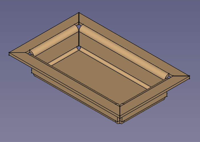
Example

A simple tray
Preparation
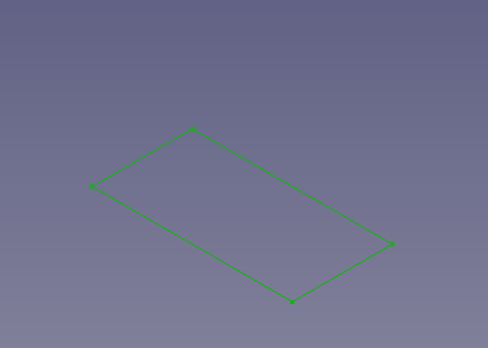
This tray is made of a rectangular blank with walls added to its outline edges. And so one outline sketch for the blank has to be prepared in advance.

Just a rectangular outline
Workflow
- Create a blank
- Select the outline sketch
- Press the
 Make Base Wall button
or use the keyboard shortcut: C then F
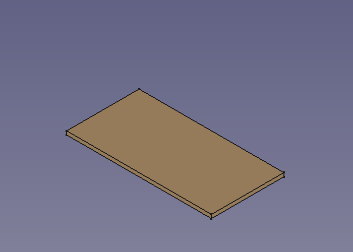
(The blank is padded in z direction
- Select the outline sketch
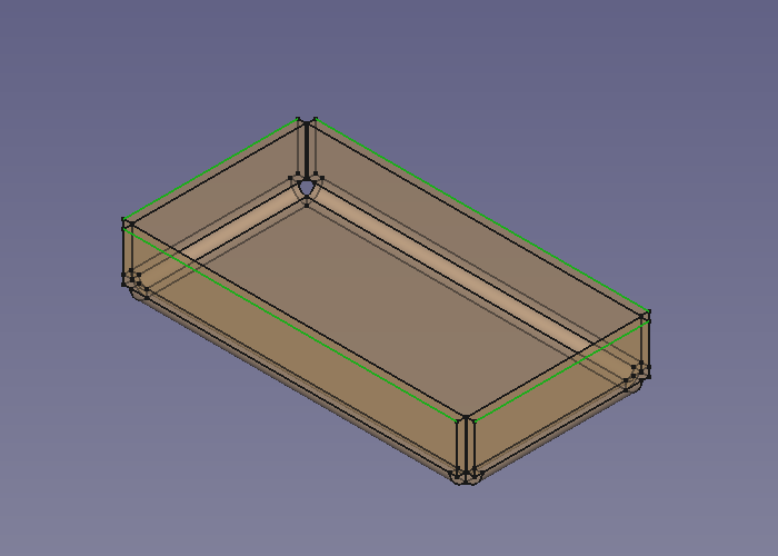
- Add walls to the outline edges
- Select the blank's outline edges
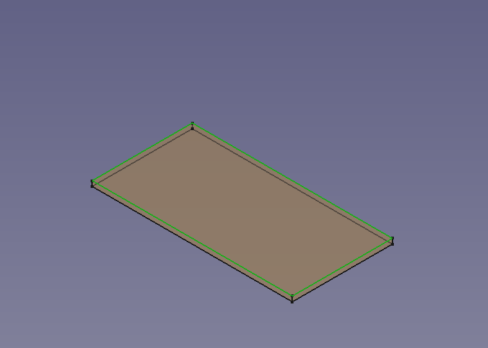
- Press the
 Make Wall button
or use the keyboard shortcut: W
- If the fold is 90° down set the value of invert property to true to reverse the direction (and length to a lower value for smaller walls)
- Select the blank's outline edges
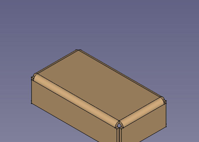
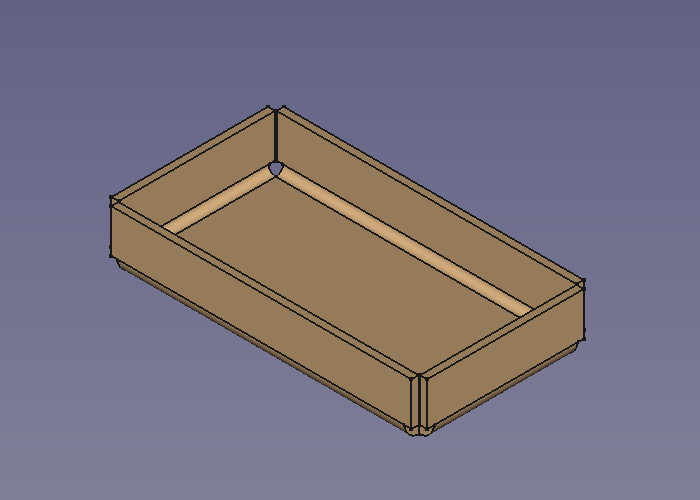
- Add some more walls
- Select the tray's upper outside edges
- Press the Make Wall button
or use the keyboard shortcut: W
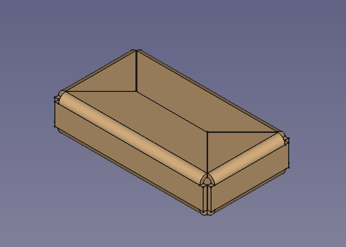
- The walls are a bit too long (but nicely trimmed) and so the length property has to be set to a lower value

- If you like the folds swing outward set the invert value to true
- Select the tray's upper outside edges


Done!