SheetMetal Extrude
This documentation is not finished. Please help and contribute documentation.
GuiCommand model explains how commands should be documented. Browse Category:UnfinishedDocu to see more incomplete pages like this one. See Category:Command Reference for all commands.
See WikiPages to learn about editing the wiki pages, and go to Help FreeCAD to learn about other ways in which you can contribute.
|
|
| Menu location |
|---|
| SheetMetal → Extend Face |
| Workbenches |
| SheetMetal |
| Default shortcut |
| E |
| Introduced in version |
| - |
| See also |
| SheetMetal ExtendBySketch |
Description
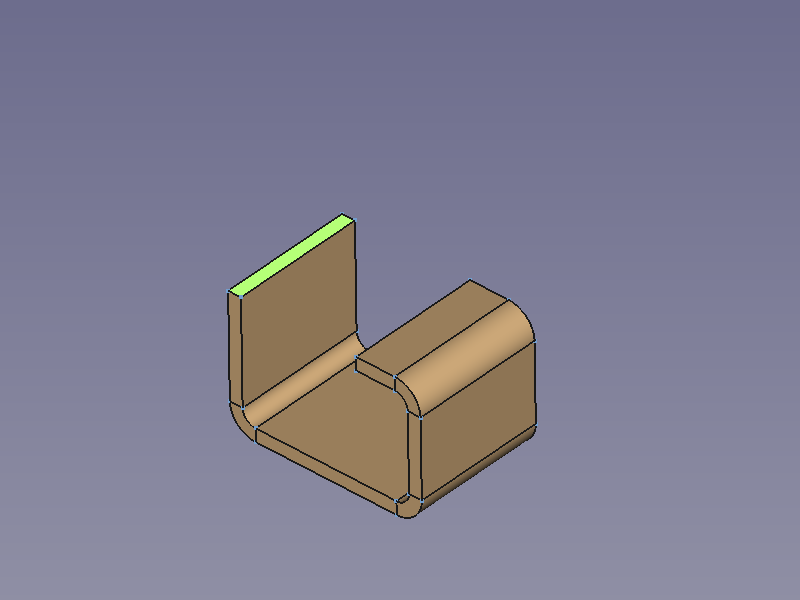
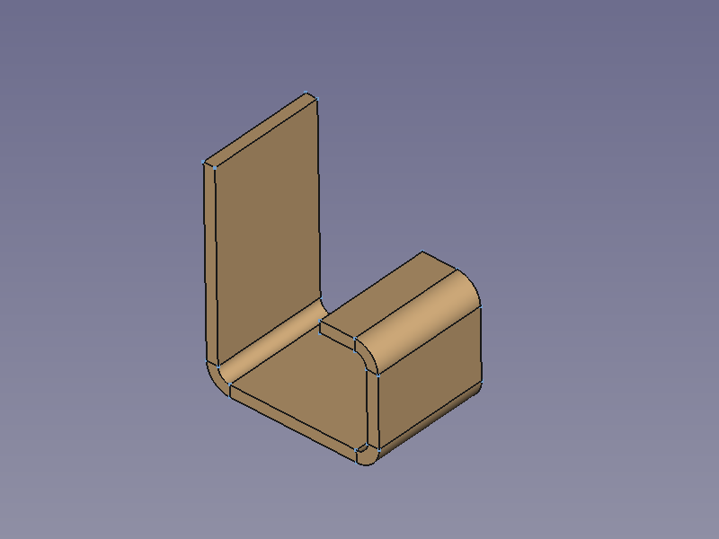
The SheetMetal Extrude command extends a sheet metal plate at a selected edge face.
It creates a simple extension along the face normal of the selected edge face:
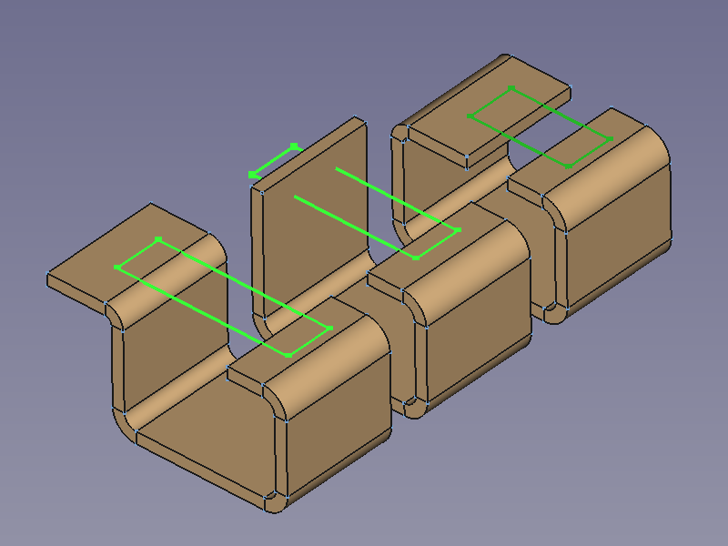
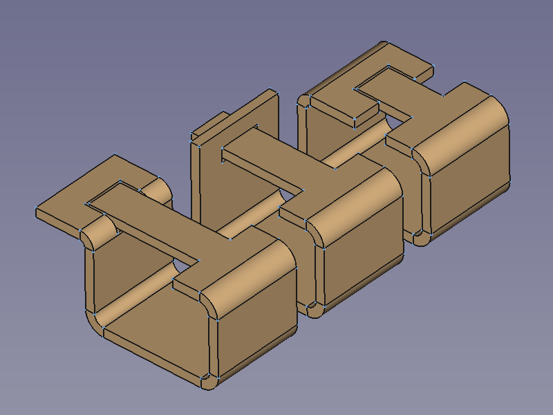
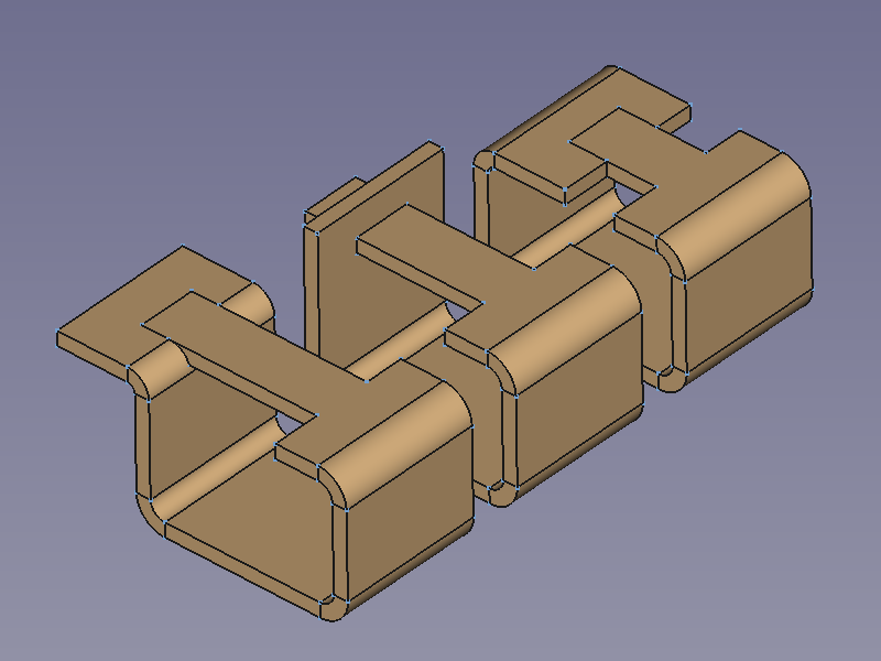
If an outline sketch is added it creates interlocking geometry to close a profile:
Three profiles with outline sketches to add → three results
Usage
Simple Extension
- Select one or more edge faces to be extended.
- There are several ways to invoke the command:
- Press the
Extend Face button.
- Select the Sheet Metal →
Extend Face option from the menu.
- Right-click in the Tree View or the 3D View and select the Sheet Metal →
Extend Face option from the context menu.
- Use the keyboard shortcut: E.
- Press the
- An Extend object will be created with a new face extension extruded from each selected face and the Extend properties Task Panel (introduced in version 0.5.00) opens:
- Optionally press the Select button and add or remove faces.
- Press the Preview button to finish the selection and display the changes.
- Optionally adjust Length, Offset A, and Offset B.
- Optionally check the Reversed check box to create a cut out instead of an extension (introduced in version 0.7.58).
- Optionally press the Select button and add or remove faces.
- Press the OK button to finish the command and close the Task Panel.
- Optionally adjust the parameters in the Property View.
Task Panel
A Task Panel was introduced in version 0.5.00
Double-click an existing Extend object in the Tree View to re-open the Task Panel and edit the parameters.
- Select: Changes the amount of faces in the base Object property.
- Length: Sets the length property.
- Offset A: Sets the gap 1 property.
- Offset B: Sets the gap 2 property.
- Reversed: Toggles the reversed property. introduced in version 0.7.58
- Refine: Toggles the Refine property.
Note: Since version 0.7.57 a different Task Panel will be displayed if the DataSketch property is not empty. See ExtendBySketch for additional information.
Interlocking Extension
Even though it still can be done this way it is recommended to use the Extend by Sketch command for this task now (version 0.7.57 and above).
- (Prepare a
sketch for interlocking tabs)
- Select the edge face to be extended.
- Invoke the command as described above.
- Press the OK button to finish the command and close the Task Panel.
- In the Property View press the … button of the DataSketch property.
- The Link dialog window opens.
- Select the prepared sketch from the list
- Press the OK button to close the dialog.
- Set the property DataUse Subtraction to
trueto create cut-outs to make room for the extensions. - Set the property DataOffset to adjust the clearance around the extension.
Three profiles → position of the sketches → results without cut-outs → final results
Notes
- A sketch can contain more than one outline.
- After inserting a sketch, at least one of its outlines must at least touch one opposite face or the tool will fail to create any extension or cut-out.
- Just one outline touching an opposite face is enough to create extension geometry from all outlines of the sketch.
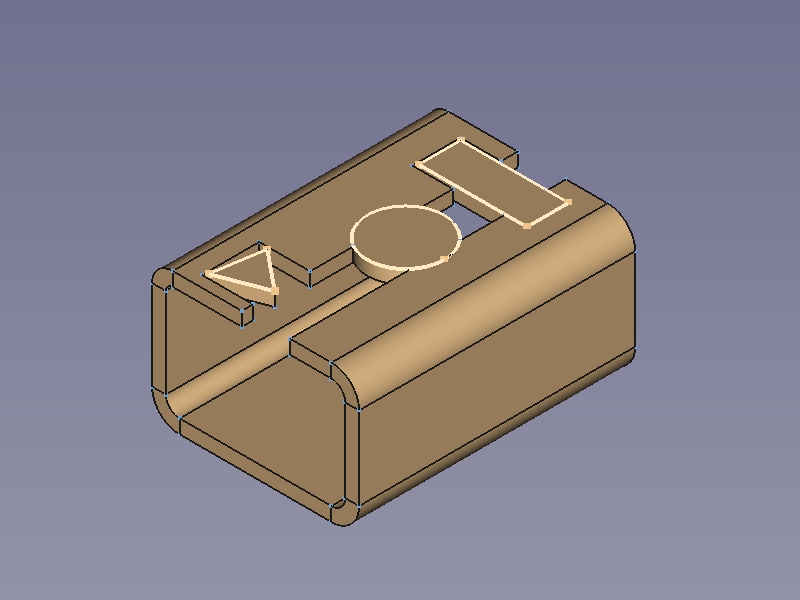
- Each cut-out will have a cuboid shape, no matter what shape the corresponding outline sketch is.
- Shapes other than rectangles may behave little bit strange and even though the object can be unfolded, the result will not turn out as expected.
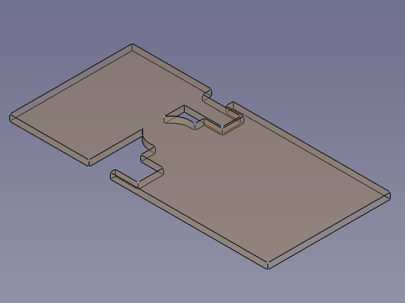
Three outline sketches and their resulting extensions: separate triangle plate with a rectangular cut-out, circle without clearance → unfold solid is split at an unexpected position
- In an extension operation it is recommended to leave the property DataRefine set to
true(default).
- The extension operation with a linked sketch may fail due to coplanar issues if the face on the sketch side and the face on the opposite side are coplanar, but with opposite orientations. A small offset may help in such a case.
Properties
See also: Property View.
A SheetMetal Extend object is derived from a Part Feature object or, if it is inside a PartDesign Body, from a PartDesign Feature object, and inherits all its properties. It also has the following additional properties:
Data
Parameters
- Database Object (
LinkSub): "Base object". Link to the object and the planar faces to be extended. - Datagap1 (
Distance): "Gap from the left side". Default:0,00 mm. - Datagap2 (
Distance): "Gap from the right side". Default:0,00 mm. - Datalength (
Length): "Length of Wall". Default:10,00 mm.- extension length if Datareversed =
false. - cut out length if Datareversed =
true. (introduced in Version 0.7.58)
- extension length if Datareversed =
- Datareversed (
Bool): "Reverse extend direction (cut)". Default:false. Toggles between extension and cut out. (introduced in Version 0.7.58)
Parameters Ext
- DataOffset (
Distance): "Offset for subtraction". Default:0,20 mm. Clearance for interlocking geometry - DataRefine (
Bool): "Use Refine". Default:true. - DataSketch (
Link): "Wall Sketch". Link to the sketch defining the interlocking geometry. Empty by default. - DataUse Subtraction (
Bool): "Use Subtraction". Default:falseToggles if intersected walls of the same object are cut out for tabs defined by the linked Sketch.
