Creating a simple part with Draft and Part WB/ru
| Topic |
|---|
| Моделирование |
| Level |
| Для начинающих |
| Time to complete |
| 1.5 часа |
| Authors |
| heda |
| FreeCAD version |
| 0.19 или выше |
| Example files |
| See also |
| Создание простой детали в верстаке Part, Создание простой детали с помощью верстаков Draft и Part |
Введение
Это руководство можно рассматривать как первое введение в Верстак Draft FreeCAD. В нем для создания трехмерных тел используются двухмерные виды с использованием Верстака Part. Рекомендуем читателю сначала проработать руководство Создание простой детали в верстаке Part, в котором одна и та же деталь создается с помощью различных способов с использованием большинства основных элементов пользовательского интерфейса FreeCAD. Предполагается, что пользователь уже вкратце знаком с пользовательским интерфейсом и некоторыми способами работы с FreeCAD. Целью руководства является не показать наиболее эффективный способ работы в программе, а скорее показать различный функционал FreeCAD. Как и где его использовать - решать пользователю.
Содержание руководства
- Описание модели
- Создание 2D профиля
- Почему вытягивание может вызвать сбой
- Вытягивание профиля
- Создание сквозного отверстия
- Создание эскиза из 2D профиля
- Качество моделей
- Подведение итогов
Создаваемая модель
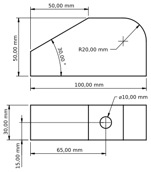
Создание 2D профиля
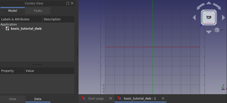
Создайте новый документ и сохраните его. Измените вид на Вид сверху и переключитесь на
Верстак Draft, ваш экран должен выглядеть так, как показано ниже. Если миллиметровая сетка не видна, включите ее нажатием
Переключить сетку.
Для создания профиля нарисуйте какой-нибудь Прямоугольник на XY плоскости щелкнув мышкой в двух точках 3D вида на концах диагонали прямоугольника. В этот момент откроется Панель задач, в ней конечно вы можете ввести координаты концов диагонали, но можете обойтись и без нее. На вашем 3D виде должен быть изображен прямоугольник как на картинке ниже.
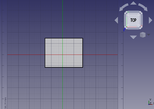
Когда работаете в Верстаке Draft, то почти всегда работаете с 2D плоскостью. Эта плоскость называется Рабочей плоскостью, и если используются настройки по умолчанию, она будет автоматически выравнивать себя с текущим 3D видом. Поэтому, пока 2D профиль не закончен, лучше просто работать на виде сверху и не крутить изображение в пространстве. Если положение в пространстве изменилось, вернитесь к виду сверху прежде чем выполнять любую другую команду Верстака Draft.
На виде сбоку наша модель имеет размеры 100х50 мм, и было бы хорошо, если бы ее нижний левый угол был помещен в нулевую точку глобальной системы координат. Это можно сделать через Редактор свойств. Для этого выделите мышкой Rectangle, затем измените свойство Position прямоугольника (0, 0, 0), исправьте height на 50 мм и length на 100 мм как на картинке ниже.
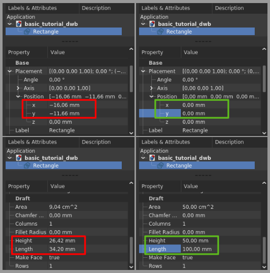
Прямоугольник завершен и после нажатия на кнопку Уместить все он должен выглядеть как на картинке ниже.
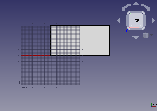
Затем мы разобьем прямоугольник на четыре отрезка. Для этого сначала выберите Rectangle, а затем вызовите команду Упростить чертеж. Заштрихованный прямоугольник исчезнет, а объект в Дереве проекта теперь называется Wire/Проволока вместо Rectangle/Прямоугольник, как на картинке ниже. Повторный вызов Упростить чертеж разобьет Проволоку на Отрезки как показано на средней картинке ниже.

Внимательный читатель заметит, что на дереве проекта уже для объекта проволока иконка сменилась на синий кубик. Эта иконка с синим кубиком используется для общих геометрических объектов (геометрические объекты верстака Part имеют свою специфику, но это оставим продвинутым читателям). Выберите левый вертикальный отрезок и вызовите команду Улучшить чертеж, бывший отрезок теперь будет иметь другую иконку и сменит наименование на Line/Линия. Это теперь объект Верстака Draft у которого можно задать свойства, например, начальная точка и конечная точка в Редакторе свойств. Это невозможно сделать для объектов Отрезок.
Создание скругления
Start by selecting the upper right corner edges, use menu Edit → Box selection Box selection, hold down the
Left Mouse Button and drag from right to left and release the LMB. When dragging from right to left the resulting selection includes everything fully or partially within the selection area. If one drags from left to right, only objects fully enclosed by the selection area are included in the resulting selection. The actual selection happens when the left mouse button is released, and there is no preview of what will be selected.

With the top right corner edges selected, invoke the command Fillet in the Draft Workbench. Check Delete original objects and change the radius to 20 mm and hit enter.
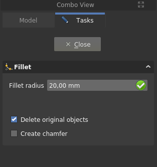
The Fillet is created and your model should now look like below.

Creating the chamfer
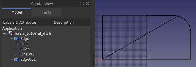
To make the chamfer we need to have a line with the correct inclination and also be able to position it correctly. Let us begin with the position, which is on coordinate (50, 50, 0). In the current profile we do not have a point there, so let’s create one by making a temporary help line. First select the left vertical Line, then create the help line by Duplicate selection in Edit → Duplicate selection, Line001 is created. Use the Property editor and move Line001 50 mm in x-direction using the Placement property. Next duplicate the lower horizontal edge, and change the angle of the edge to 30 degrees, once again using the Placement property. The model should now look like the image below.
Next, move the angled line into position. For this we make use of Draft Move along with the snap functionality in the Draft Workbench, more specifically end point snap. First make sure that your snap toolbar looks similar to below.

Then select the angled line, Edge001, press Move and a task panel opens up.
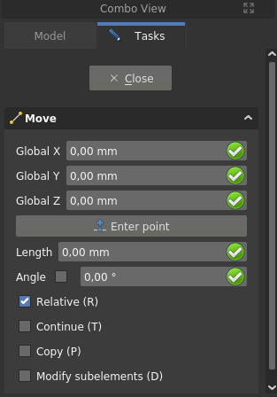
Make sure that Copy is unchecked. Hover the mouse over the upper quarter of the angled line, once the white dot is displayed at the right spot and the end point symbol shows, click the LMB. Move the mouse to the upper quarter of the help line, once the white dot and end point symbol appear, click the LMB. The sequence is illustrated below.
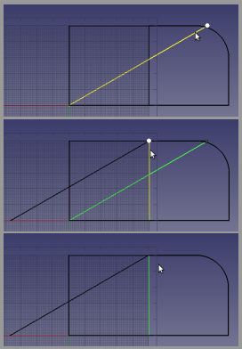
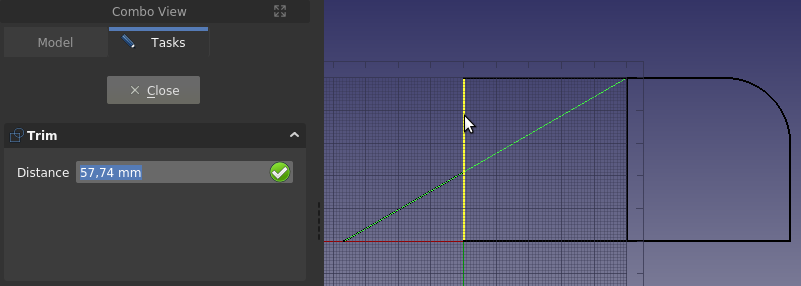
The line is now in the correct position, but it is too long. To adjust the length Draft Trimex will be used. Select the angled line, Edge001, press Trim and then click on the lower part of the left-most vertical line, Line, to use it as the cutting edge. The projection of the point where the cutting edge is selected onto the edge to be cut, determines the result. If you select the left-most vertical line near its top end, the wrong part of the angled line would be trimmed. The image below shows the Trim command invoked, the pre-selected vertical line, and the cursor hovering over the wrong end of that line. If you look carefully you can see the preview of the result.
Also trim the left-most vertical line to form the lower corner of the chamfer. Select the angled line, Edge001, near its top right endpoint for a correct result. If you make a mistake while trimming, just use Undo and
Refresh (the latter often called recompute) and try again.
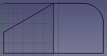
To trim the upper horizontal edge, the Fillet needs to be downgraded so that the upper edge is its own object in the Tree View. If you attempt to trim it without first having done the downgrade, the trimming function attempts to trim the arc in the fillet. Because the trimming edge, the middle vertical line, is perpendicular to the edge to be trimmed, you cannot control the trim result by picking a correct point on the trimming edge. Here you need the flip the default solution by holding down the Alt key as you select the cutting edge.
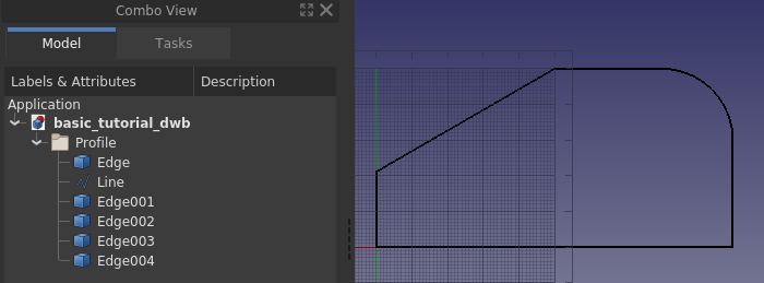
The profile is ready and shown below with the edges organized in a Group named Profile (or labeled to be precise in FreeCAD lingo), along with the help line deleted. Groups can be used to organize the features in your FreeCAD documents, its usage is similar to a folder structure on a computer’s file system. To move things in and out of the group, use drag and drop in the Tree View.
Why extruding can fail
Save the document. We will experiment in this paragraph and we want to be able to go back to the current model.
Let’s jump right in: select all the edges and the line in the group Profile, and in the Part Workbench invoke the command
Extrude. A task panel opens, accept all the defaults and click OK.

That did not work out, but it sounds easy enough to fix the error, we just need to specify a direction. Click OK to get back to the task panel and select custom direction.
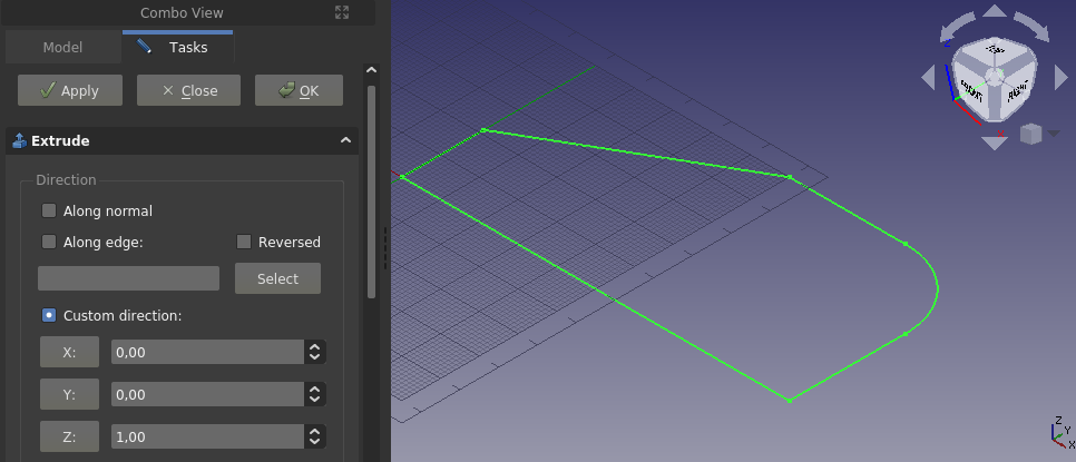
Accept the default z-axis and once more click OK.
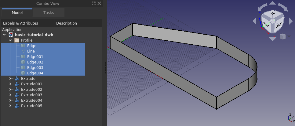
We managed to make a fence like structure, judging from the Tree View every edge is treated separately. It is not the filled solid that we want. Hit Undo, and let’s try something else.
Scrolling all the way to the bottom of the Extrude task panel there is an option Create solid, check that option and click OK.
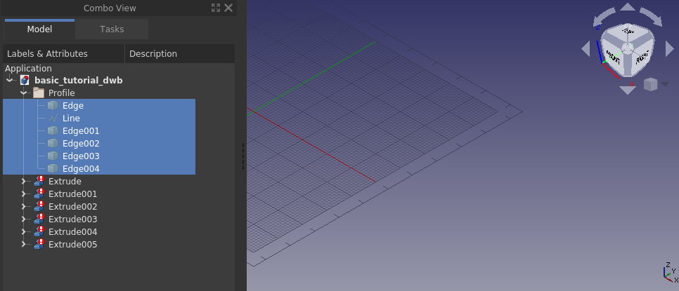
Everything disappeared, clearly that did not work either. Let’s go through why none of these ways are working. In the first case we got an error that the direction could not be determined. A flat face has a normal, i.e. direction, a line does not. Since from our second attempt we know that it worked when providing a direction, the error simply comes from trying to extrude a line without knowing a direction. The observant will say that an arc has a normal (direction), this is true. If you select only the edge that is the arc, FreeCAD will extrude it, also with default settings.
In the second case it worked, but we also got an extrusion for each edge we had in our selection. The resulting features however are not what we want, i.e. a solid.
In the third case we checked Create solid, and ended up with everything disappearing. The objects in the Tree View have a different icon as well, there is a white exclamation mark on a red background, that particular overlay icon means that the object has an error that has to be tended to. One can read up on the different types of overlay icons on the wiki.
Hovering over any of the Tree View objects with the overlay icon a tool tip is displayed, it says Wire is not closed.

In our case the error is not fixable. It is geometrically impossible to create a solid out of an extruded single line. An extruded line simply becomes a sheet, or shell in FreeCAD lingo. In other words, this is not a FreeCAD limitation, it is a fundamental outcome of geometrical theory. The reason why the 3D view goes completely blank is that the created features, or objects in the Tree View, have errors in the produced shape, and thus contain nothing to render. FreeCAD does however create the new document objects (in this case extrusions) and thus hides any geometry/object used for making the new document objects. That is why the screen goes blank when trying to make a solid out of a line, or lines.
The tool tip says it all, in order to extrude into a solid one needs a closed wire, or a face. A face is, per definition, simply a closed wire that is filled. One way to create a closed wire out of our profile edges is to select them all and apply Draft Upgrade. If applied once it becomes a wire, while at the same time it consumes the individual edges from the Tree View. If applied twice it becomes a face, either of those allows for a successful solid extrusion.
Before going on to the next paragraph: open the previous version of the document.
Extruding the profile
Another way to create the closed wire is with the Shape builder command from the Part Workbench, which allows for making a wire without consuming the individual edges. Part Shape builder is a powerful tool to create any geometric entity in FreeCAD that can be used further to create complex solids, the simplest example is creating a line between two vertices. Click Part Shape builder to bring up the task panel.
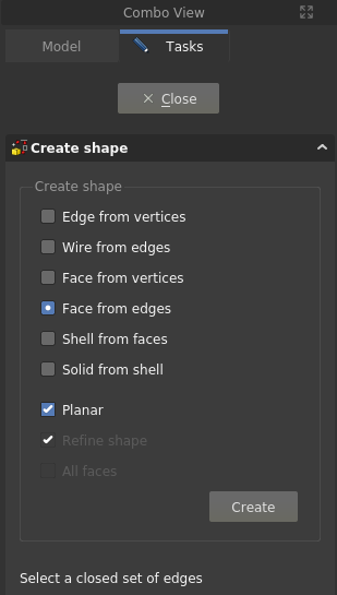
We can use either Wire from edges or Face from edges. Multiple selections have to be made with the Ctrl key pressed down. Let’s use Face from edges, once that option is selected one can also select Planar, do that as well. Then select all edges in the profile, the order does not matter (in this case) and click Create, and then Close to come back to the Tree View. The face has been created.

Select the Face and invoke Part Extrude, set the extrusion length to 30 mm and click OK.
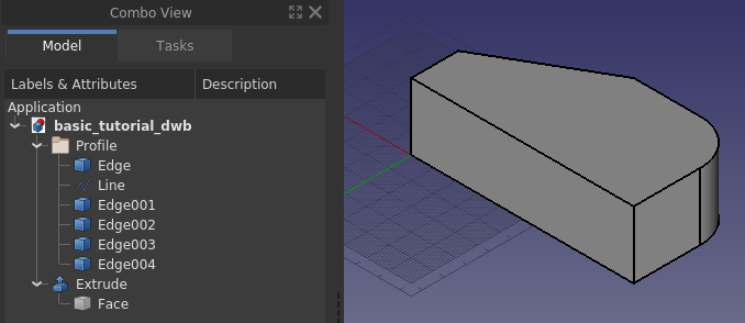
Creating the through hole
To make the through hole we need a cylinder correctly positioned to make a boolean cut with.
Create a cylinder, and position it correctly. In this case the radius is 5 mm, the height is set to 60 mm. For the placement, first it is rotated -90 degrees around the x-axis, then positioned at (65, -5, 15). The negative 5 in the y-direction is because the height is 10 mm longer than needed.

It does not hurt to make the height of the cylinder longer than needed. For a simple model like this it will not matter if the cylinder is the exact height of the profile. It is however good practice to avoid co-planar faces to prevent numerical errors in the geometric kernel that can sometimes result in strange effects, or failures in subsequent operations.
With a final boolean cut, and after changing the appearance of the resulting object, the model is completed.
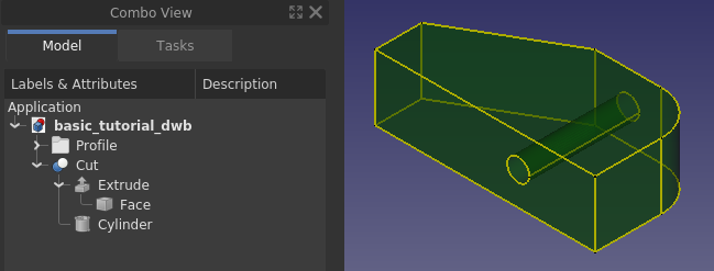
Making a sketch out of the 2D profile
Using the Draft Workbench is one way of creating a 2D profile. In the Draft Workbench a wire can be made in 3D space. FreeCAD provides another tool to make 2D profiles – the Sketcher Workbench. Using a sketch is a more versatile way to create a 2D profile. Any 2D profile made in the Draft Workbench can be converted to an unconstrained sketch.
Start by hiding the Cut feature and make the edges and the line in the profile visible. Select the edges and the line and from the Draft Workbench press the toolbar button Draft to Sketch. You should see the same as in the image below.
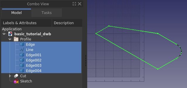
Next, hide the original edges and double-click the Sketch object in the Tree View, bringing you to the following state, i.e. the Sketcher task panel opened.
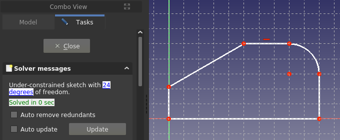
This is how it looks when one edits a sketch. Since this is not a tutorial for using the Sketcher just go ahead and close it. If you want an introduction to sketching, which is a core workflow in any 3D parametric CAD, please follow the sister tutorial Creating a simple part with PartDesign.
With the Sketch closed and selected, from the Part Workbench use Extrude in the same way as before. The basic block of the simple model is ready once again.
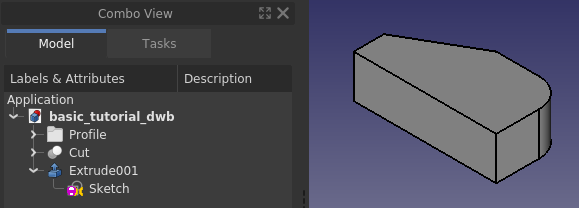
Quality of models
Sooner or later when working with 3D parametric CAD you will come across a broken model, either one you have made yourself, or a model that you have imported. A broken model can work for its purpose, but more often than not, there are subsequent operations that simply will not work. To repair a broken model one has to know what to repair, this is where the built-in quality check tools in FreeCAD come in.
First let us check the quality of the recently created Extrude001. With the Part Workbench active, first select Extrude001 and then use the command Check geometry. Check all settings checkboxes except the top one, and click the Run check button.
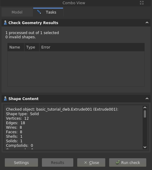
Our model is OK, no errors are reported. There is also a listing of the models content, or in FreeCAD lingo, the content of the shape, i.e. how it is put together from ground up. Here one can see that apparently to make a solid one also needs a shell, and the shell is made out of faces, and so on. In other words, you can create any solid by simply starting out by making points, or vertices, from those one makes edges, and from those one creates wires, and out of the wires one makes faces which are then stitched into a shell, from which one finally arrives at a solid. A solid can only be made from a watertight shell. A not watertight shell is a common source of troublesome CAD models, it can for example happen with imported geometry created in a different software, especially when using the commonly available neutral file formats.
Another check one can do is related to the Sketch. Close the task panel for the geometry check. Select the Sketch, expand Extrude001 in the Tree View if needed in order to see the sketch object. Switch to the Sketcher Workbench, use the command
Validate sketch, a task panel opens. In the task panel, click the Find button for Missing coincidences. It highlights and reports 6 of them, i.e. all the points where the edges meet.
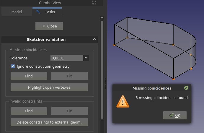
Click OK in the pop-up dialog and then click the Fix button to heal the Missing coincidences. If you close the task panel, and go into edit mode of the Sketch, it reports 12 degrees of freedom, as opposed to the earlier 24. That was achieved through adding coincident constraints to the endpoints of the edges.
The observant reader notices that when using edges from Draft those had to be joined into a closed wire to make a solid extrusion, whereas in Sketcher that was apparently not needed. The logic here is that the sketch is one object, and the extrusion of one object is treated as if it was a closed wire (in this case).
Finally it should be pointed out that, although creating subsequent objects from sketches with open vertices can work, it is best practice to not have any, as well as to have a fully constrained sketch (as opposed to an under-constrained sketch). The reason why it works here is that the sketch is created from a Draft profile constructed in such a way that the endpoints of the edges match without any gaps. If you draw by hand in a sketch, and also try to match endpoints by hand, it is virtually guaranteed that endpoints will not match, i.e. the gaps (although not really visible on the screen) will be large enough that the geometric kernel cannot consider the edges to be geometrically joined.
Wrapping up
Having gone through the tutorial you have become somewhat familiar with the basic functionality of FreeCAD, along with the core workbenches Part and Draft. You are also aware of the existence of the Sketcher Workbench, which for many experienced users is the sole tool used to create 2D profiles later utilized in solid feature operations. The use of sketches is a core concept in the PartDesign Workbench. It is suggested that you learn sketches and PartDesign Workbench next if your focus is on creating solids. The sister-tutorial Creating a simple part with PartDesign makes the same model as this tutorial. If your focus is modeling buildings your next learning should be the Draft and Arch workbenches.
At last, FreeCAD is made by volunteers in their spare time. If you want to further advance FreeCAD’s capabilities, consider contributing to FreeCAD, for example by improving the documentation.