FEM CalculiX Cantilever 3D/es
| Tema |
|---|
| Finite Element Analysis |
| Nivel |
| Beginner |
| Tiempo para completar |
| 10 minutes |
| Autores |
| Bernd |
| Versión de FreeCAD |
| 0.16.6377 or above |
| Archivos de ejemplos |
| Ver también |
| None |
Introduction
Introducción
Este ejemplo pretende mostrar cómo se ve un simple Análisis de elementos finitos (FEA) en FreeCADs FEM Workbench y cómo se pueden visualizar los resultados. Se muestra cómo activar un FEA y cómo cambiar el valor de la carga y la dirección de la carga. Además, dado que el archivo de ejemplo se proporciona con cualquier instalación de FreeCAD, es fácil verificar si el módulo FEM está configurado correctamente.
Requirements
Requisitos
- Versión de FreeCAD = 0.16.6377 o superior.
- Esto se puede verificar en el menú Ayuda -> acerca de FreeCAD. El número de Revisión tiene que ser superior a 6377
- No se necesita software externo para cargar el archivo de ejemplo, ver la malla y la geometría, así como para visualizar los resultados.
- Para volver a ejecutar el FEA, el software de resolución de problemas CalculiX debe estar instalado en su computadora. Probablemente el solucionador ya se haya instalado junto con FreeCAD. Si el solucionador CalculiX no está instalado, consulte FEM Install.
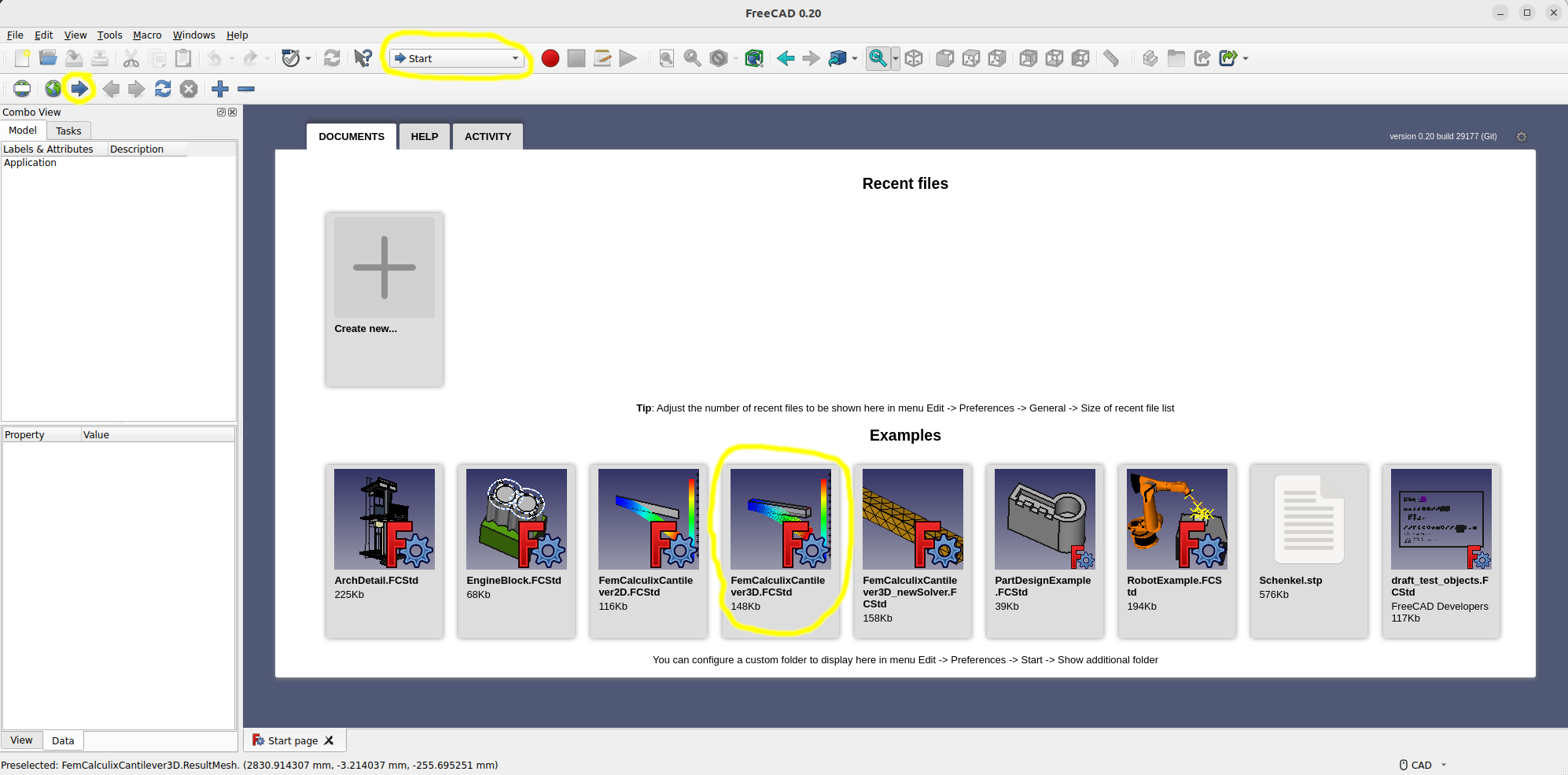
Set up the example file
Load the example file
- Start FreeCAD.
- If the Start Workbench is not activated, load it and open the start page.
- Open the example file FemCalculixCantilever3D.FcStd 0.21 and below, or FEMExample.FcStd 1.0 and above.
Activate the analysis container
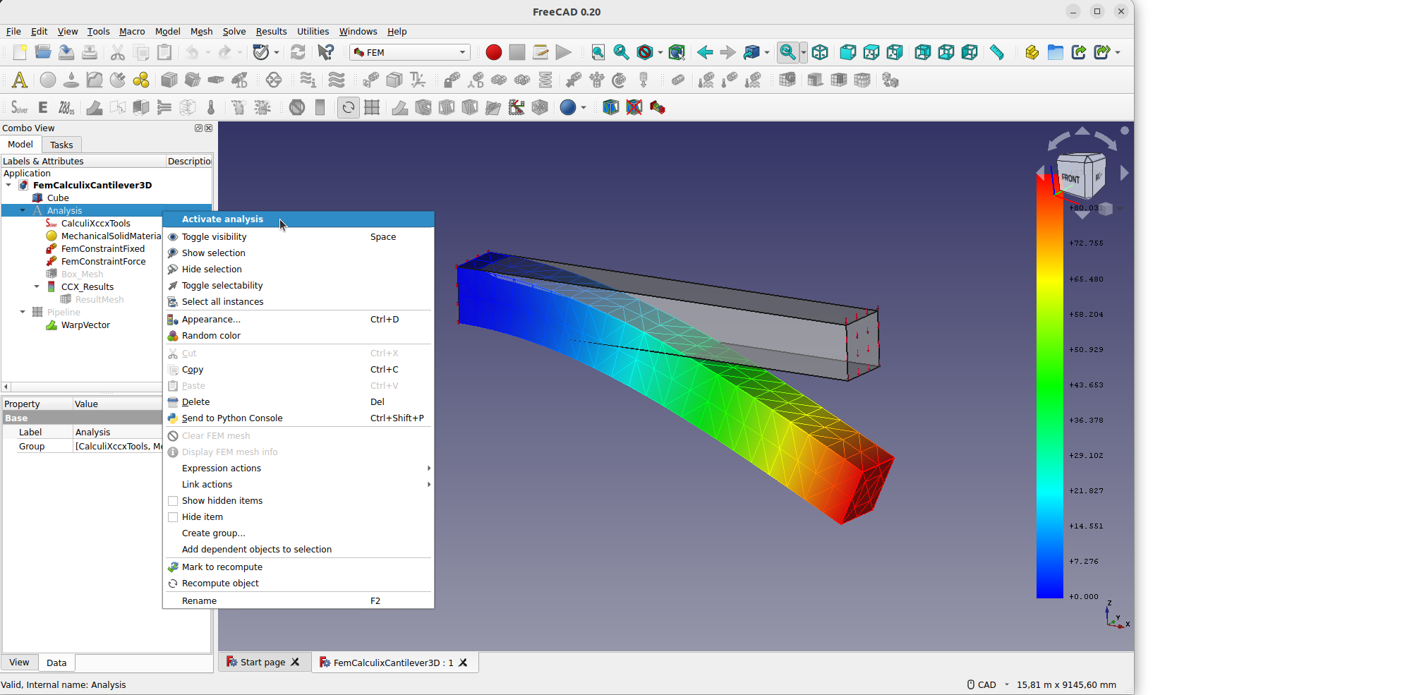
Analysis container and its objects
- If the analysis is activated, FreeCAD itself will change the current workbench to FEM.
- 1.0 and above: The following objects can be found in the
 Group container 3D.
 - The
 Analysis container holds at least the 5 objects needed to make a static mechanical analysis:
 a solver
 a material
 a fixed boundary condition
 a force load
 a FEM mesh
- In this example,
 results are already included as well.
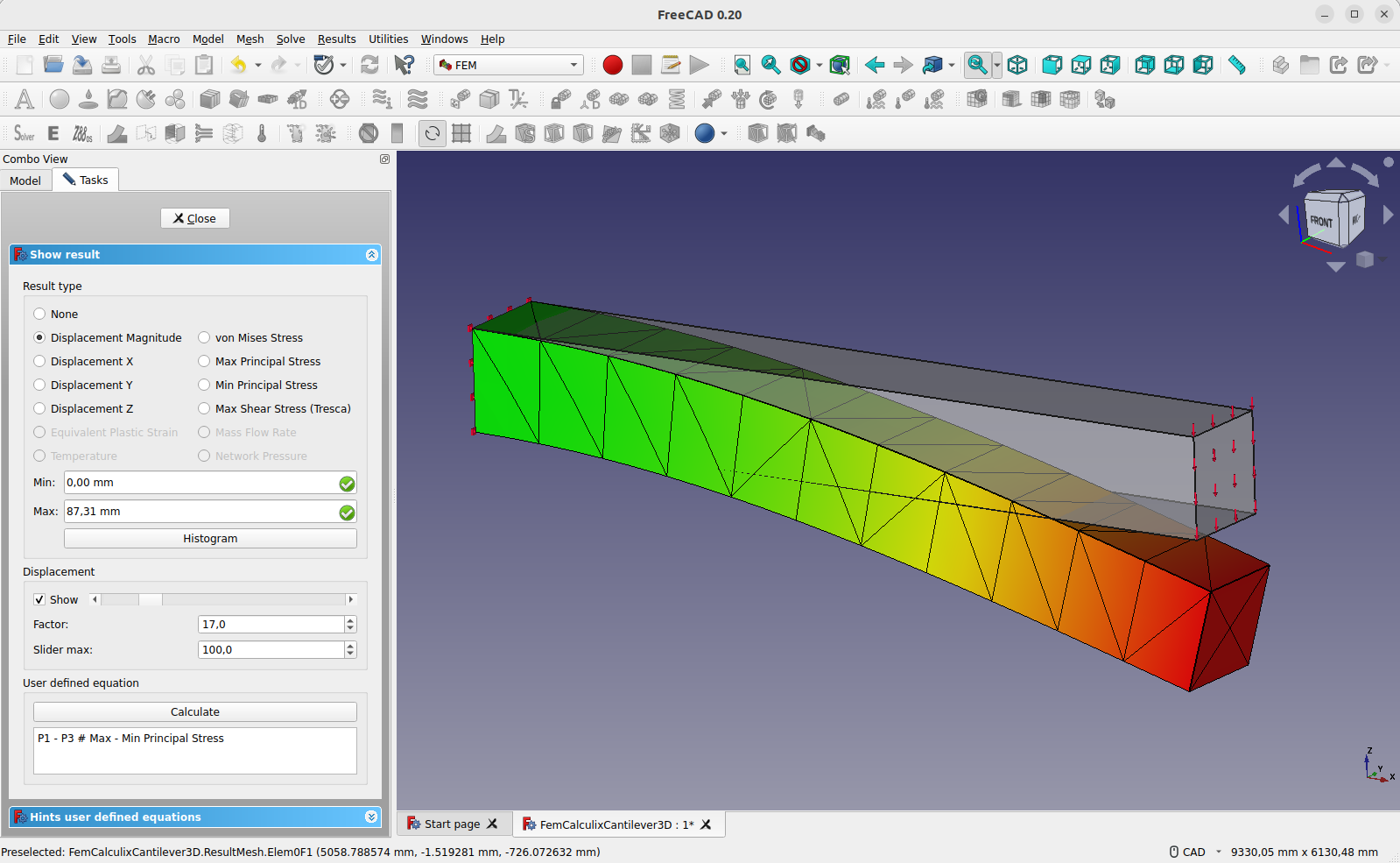
Visualizing Results
- Be sure the analysis is activated.
- Be sure the analysis still contains the result object, if not just reload the example file.
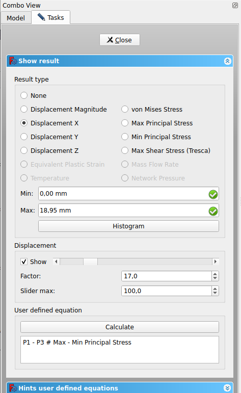
- Double click the result object , or select it and press the Show result button.
- In the task window, choose
z-Displacement. It shows-86.93 mmin negative z-direction. This makes sense since the force is in negative z-direction as well. - Activate the check box besides the bottom slider of displacement show.
- The slider can be used to alter the mesh to view the deformation in a simplified manner.
- Choose among the different Result types to view all in the GUI available result types.

Purging Results
- Be sure the analysis is activated.
- To remove the results: press the
 Purge results button.
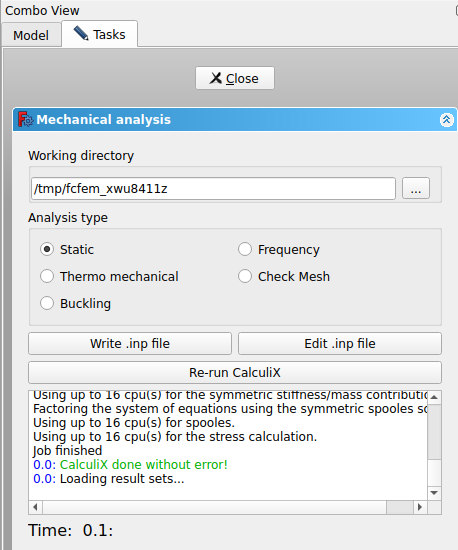
Running the FEA
- In the tree view double click on the solver object .
- The task panel of the solver object opens.
- Make sure that analysis type Static is selected.
- Press the Write .inp file button and watch the log window until it prints "write completed".
- Press the Run CalculiX button. Since this is a very small analysis it should take less than a second to run.
- Wait for the text window to print "CalculiX done without error!" in green letters, and "loading result sets ..." in the following line.
- You just have finished your first FEA in FreeCAD if there has not been any error message.
- Press the Close button in the task panel.
- A new result object should be created. You know how to visualize the results already.
- If you get the error message "no solver binary" or a similar one when triggering the analysis check FEM Install.
Running the FEA the fast Way
- In tree view select the solver object of the analysis .
- Press the
 Run solver calculations button.
 - The Calculix input file will be written, CalculiX will be triggered and the result object should be created.
Changing Load Direction and Load Value
- In the tree view expand CCX_Results and select the
 ResultMesh object and press the Space key.
- Result: The visibility of the FEM mesh will be turned off. The geometrical model is still visible.
- In the tree view double click on the FEMConstraintForce object.
- The task panel of the analysis element opens:
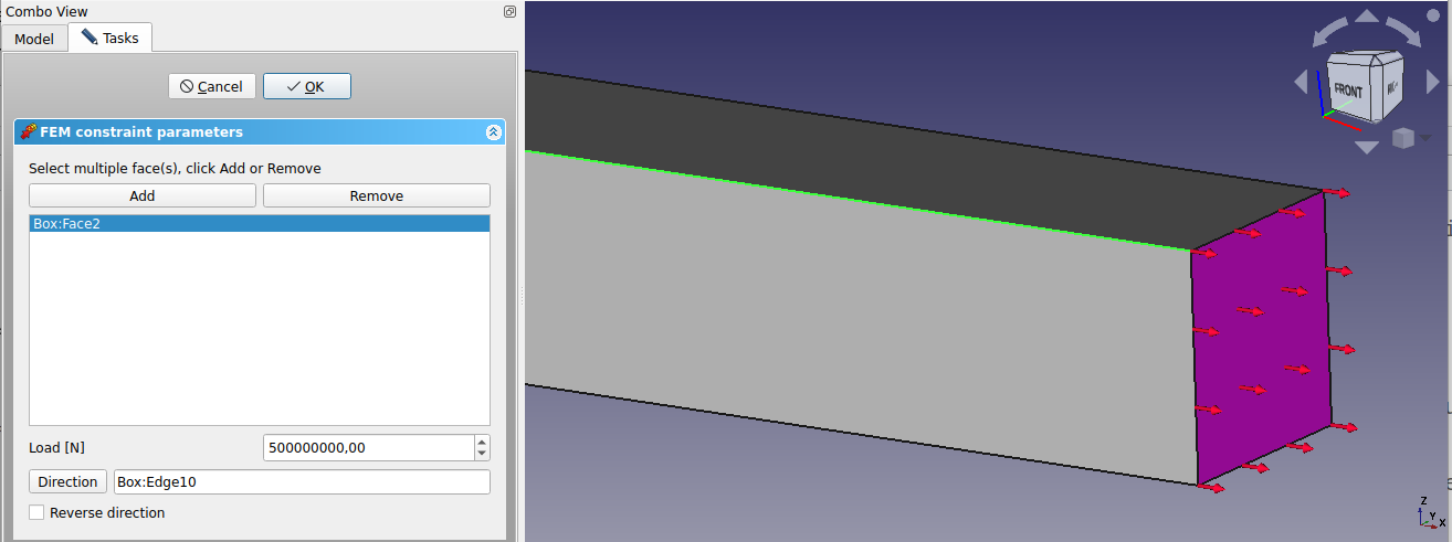
- Change the load value to 500000000 N = 500 MN (Note 0.21 and below: force unit in task window has to be in N)
- On the geometrical model click on one of the long edges in x-direction.
- Click on the Direction button.
- Result: The red arrows that illustrate force will change their direction in x-direction. They indicate the force direction.
- Since tension should be applied towards the box Reverse Direction has to be checked.
- The red arrows of the force will change their direction.
- Press the OK button in task panel.
- You know how to trigger an analysis and how to visualize results already.
- The deformation in x-direction should be 18.95 mm.
What next?
¿Qué sigue?
- Ahora hemos terminado con el flujo de trabajo básico para el Módulo FEM.
- Ahora está preparado para hacer el segundo FEM tutorial.
- Crearemos el cantilever CalculiX por nosotros mismos y compararemos los resultados con la teoría del haz.
- Materials: Solid, Fluid, Nonlinear mechanical, Reinforced (concrete); Material editor
- Element geometry: Beam (1D), Beam rotation (1D), Shell (2D), Fluid flow (1D)
Constraints
- Electromagnetic: Electrostatic potential, Current density, Magnetization
- Geometrical: Plane rotation, Section print, Transform
- Mechanical: Fixed, Displacement, Contact, Tie, Spring, Force, Pressure, Centrif, Self weight
- Thermal: Initial temperature, Heat flux, Temperature, Body heat source
- Overwrite Constants: Constant vacuum permittivity
- Solve: CalculiX Standard, Elmer, Mystran, Z88; Equations: Deformation, Elasticity, Electrostatic, Electricforce, Magnetodynamic, Magnetodynamic 2D, Flow, Flux, Heat; Solver: Solver control, Solver run
- Results: Purge, Show; Postprocessing: Apply changes, Pipeline from result, Warp filter, Scalar clip filter, Function cut filter, Region clip filter, Contours filter, Line clip filter, Stress linearization plot, Data at point clip filter, Filter function plane, Filter function sphere, Filter function cylinder, Filter function box
- Additional: Preferences; FEM Install, FEM Mesh, FEM Solver, FEM CalculiX, FEM Concrete; FEM Element Types
- Getting started
- Installation: Download, Windows, Linux, Mac, Additional components, Docker, AppImage, Ubuntu Snap
- Basics: About FreeCAD, Interface, Mouse navigation, Selection methods, Object name, Preferences, Workbenches, Document structure, Properties, Help FreeCAD, Donate
- Help: Tutorials, Video tutorials
- Workbenches: Std Base, Assembly, BIM, CAM, Draft, FEM, Inspection, Material, Mesh, OpenSCAD, Part, PartDesign, Points, Reverse Engineering, Robot, Sketcher, Spreadsheet, Surface, TechDraw, Test Framework
- Hubs: User hub, Power users hub, Developer hub