SheetMetal Examples
This documentation is not finished. Please help and contribute documentation.
GuiCommand model explains how commands should be documented. Browse Category:UnfinishedDocu to see more incomplete pages like this one. See Category:Command Reference for all commands.
See WikiPages to learn about editing the wiki pages, and go to Help FreeCAD to learn about other ways in which you can contribute.
Introduction
The ![]() SheetMetal workbench (an external workbench available through the Addon Manager) has grown quite powerful and merits to be appropriately documented.
SheetMetal workbench (an external workbench available through the Addon Manager) has grown quite powerful and merits to be appropriately documented.
To avoid the overcrowding of the tool pages with examples this page was added to collect parts showing and explaining special SheetMetal features.
Planned phases to generate content:
- Collecting pictures
- Adding workflow descriptions
- Adding more detailed tutorials
Hinge


Workflow Hinge:
![]() Make Base Wall,
Make Base Wall,
![]() PartDesign Pocket,
PartDesign Pocket,
![]() PartDesign Hole,
PartDesign Hole,
![]() Unfold.
Unfold.
Hinge step by step
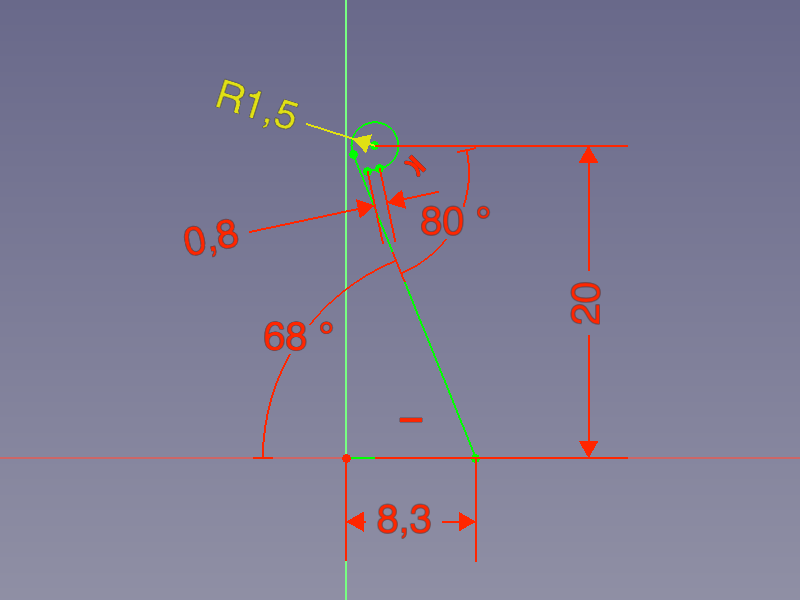
- Create a profile (a line and a tangent arc), preferably using the
 Sketcher Workbench.
 - Activate the
 Make Base Wall command to create a BaseBend object.
 - Edit the BaseBend object's parameters:
- Set DataMid Plane to
trueto let the profile extend symmetrically to both sides of the sketch plane. - Set Dataradius and Datathickness to values of your choice.
- Set DataMid Plane to
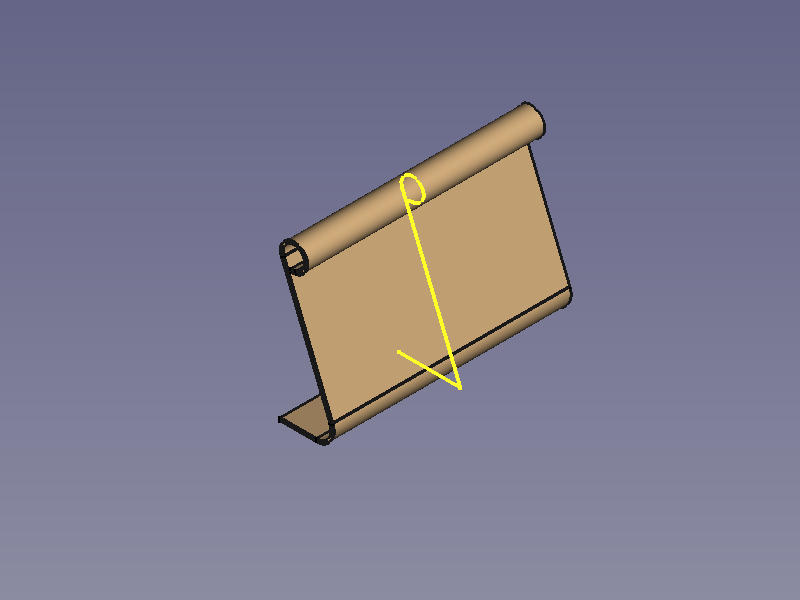
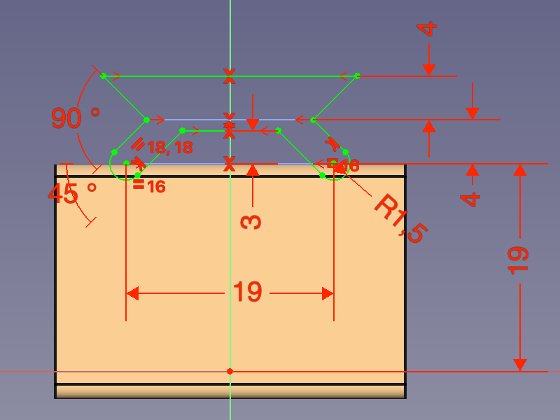
- Create a cut-out contour with the Sketcher Workbench.
- Use the
 PartDesign Pocket command to cut off one half of the Round bit.
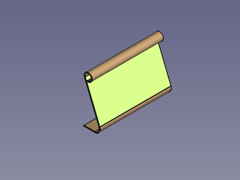
 - Create a hole pattern with the Sketcher Workbench.
- Use the
 PartDesign Hole command. Avoid the countersink and counterbore options to keep the body unfoldable.
 - Activate the
 Unfold command to get an Unfold object.
 - Done!
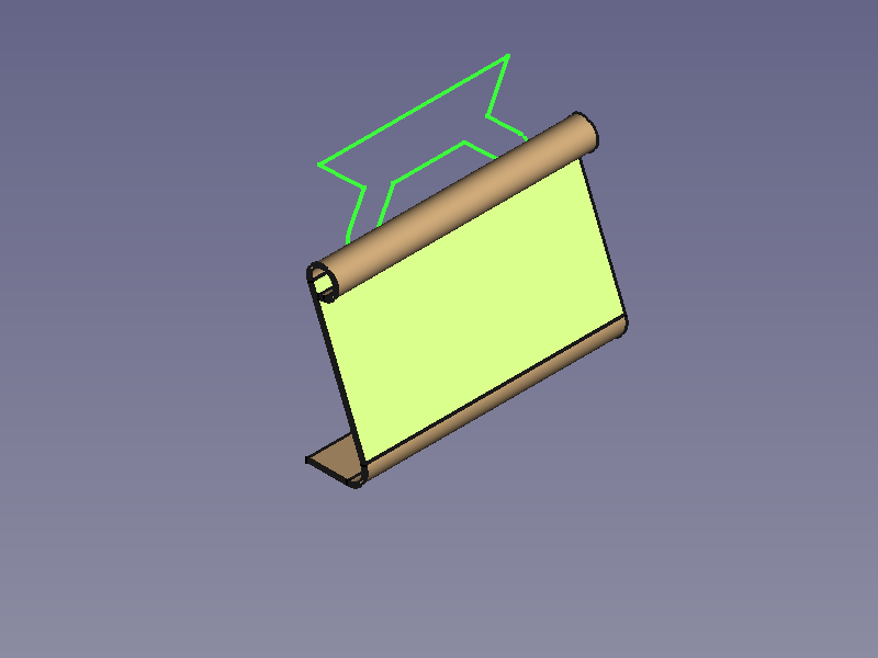
Paper clip


Workflow Paper Clip:
![]() Make Base Wall,
Make Base Wall,
![]() Sketch on Sheet,
clone, flip and fuse,
Sketch on Sheet,
clone, flip and fuse,
![]() Unfold.
Unfold.
Paper clip step by step
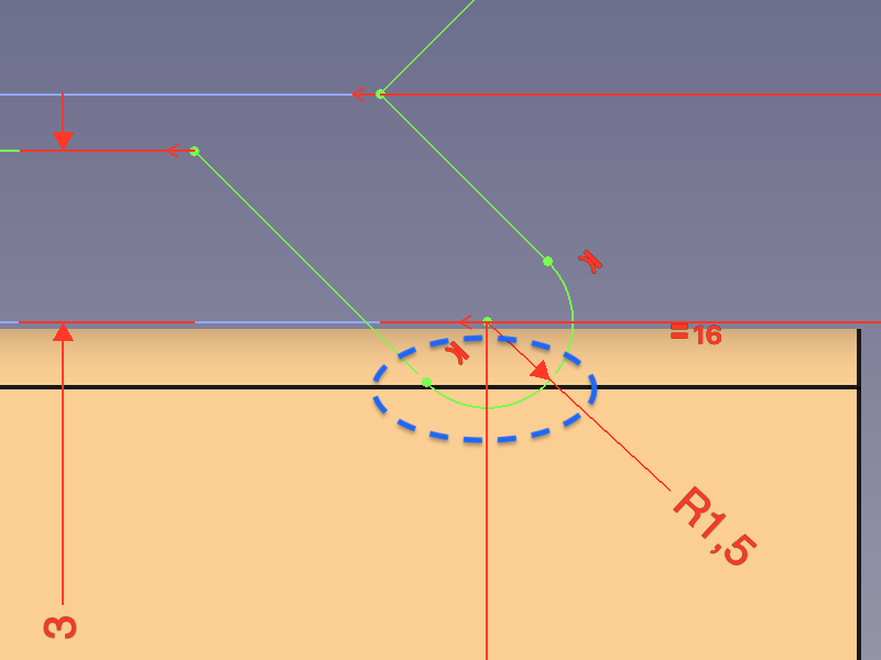
- Create a profile, preferably using the Sketcher Workbench on the XZ-plane.
- Activate the Make Base Wall command to create a BaseBend object.
- Edit the BaseBend object's parameters in the properties panel:
- Set DataMid Plane to
trueto let the profile extend symmetrically to both sides of the sketch plane. - Set Datalength to 32 mm.
- Set Dataradius to 2 mm.
- Set Datathickness to 0.3 mm.
- Set DataMid Plane to
- Select the face between the round sections and activate the Sketcher Workbench.
- To hide the curled part use the
 Sketcher View section command.
 - Create the cut-out contour.
- Finish the sketch using the
 Sketcher Leave sketch command.
 - Select the face again and add the Cut-out sketch to the selection.
- Use the
 Sketch on Sheet command to cut around the curled bit.
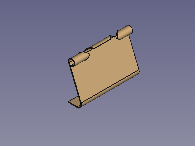
- One side is finished. We now need to find a way to mirror the body.
Potential mirror options:
- The
 PartDesign Mirrored command fails because it cannot handle SheetMetal features for some reason. So that does not work.
 - The
 Part Mirror command creates a mirrored part, but this is no longer unfoldable. So that does not work either.
 - One way that can work is to use a clone. This still can't be mirrored, but it can use axial symmetry (turn it 180°).
- Another way that works is to use a link object.
Mirror using a clone:
- Select the body from the Tree View.
- Use the
 PartDesign Clone command. It adds a new body containing a clone object.
To apply a 180° turn set the DataAngle under the Placement property of either the body or the clone to 180°. (Z-axis is default and should be fine if you started on the XZ-plane as described).

- With the body still active, use the
 PartDesign Boolean operation command to add the body of the clone and fuse both halves.
- Activate the Unfold command to get an Unfold object.
- Done!
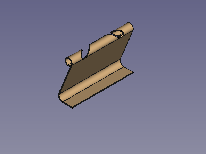
Mirror using a link object:
- Select the body from the Tree View.
- Use the
 Make link command. This adds a new link object.
 - Duplicate the link object by setting the property DataElement Count to 2.
- To apply a 180° turn set the DataAngle under the Placement property of either of the sub-linked objects to 180°. (Z-axis is default and should be fine if you started on the XZ-plane as described).
- Select both sub-linked objects in the Tree View.
- Activate the
 Part Fuse command to fuse both halves.
- Activate the Unfold command to get an Unfold object.
- Done!
Omega clamp


Workflow Omega Clip:
![]() Make Base Wall,
Make Base Wall,
![]() PartDesign Hole,
PartDesign Hole,
![]() PartDesign Fillet,
PartDesign Fillet,
![]() Unfold.
Unfold.
Hex bowl


Workflow Hex Bowl:
![]() Make Base Wall,
Make Base Wall,
![]() Make Wall,
6x
Make Wall,
6x ![]() Add Corner Relief,
Add Corner Relief,
![]() Unfold.
Unfold.

When a Corner Relief is added (right side) it can be necessary to adjust the value of the Size property.
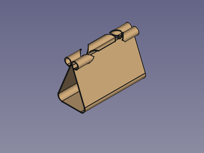
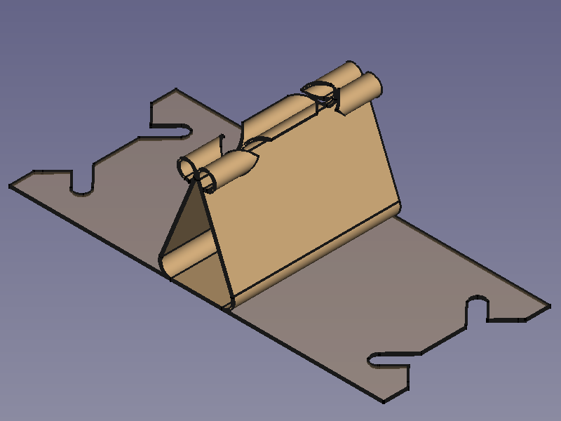
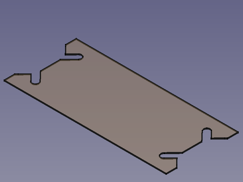
Pen clip


Workflow Pen Clip:
![]() Make Base Wall,
Make Base Wall,
![]() PartDesign Pocket,
3x
PartDesign Pocket,
3x ![]() Make Wall,
Make Wall,
![]() Unfold.
Unfold.
Extend face example


Workflow Extend Face Example:
![]() Make Base Wall,
Make Base Wall,
![]() Make Wall,
Make Wall,
![]() Extend Face,
Extend Face,
![]() Extend Face,
Extend Face,
![]() Unfold.
Unfold.
For the second use of Extend Face a Sketch with two contours is used for shape of the extension(s); and with the value of "use subtraction" set to true it provides the shape for the cut-outs, as well
USB shield contact


Workflow USB shield contact:
![]() Make Base Wall,
Make Base Wall,
![]() Extend Face,
Extend Face,
![]() PartDesign Pocket,
PartDesign Pocket,
![]() Extend Face,
Extend Face,
![]() Make Wall,
Make Wall,
![]() Unfold.
Unfold.
(The pull relief is just an artistic expression of what could be hidden inside a real plug)
SheetMetal properties
This section tries to explain the properties of each SheetMetal object with simple images, where applicable.
BaseBend object

![]()

Selected sketch +
![]() Make Base Wall
→ BaseBend object with default settings
Make Base Wall
→ BaseBend object with default settings
![]()

Edit Datalength: Default length → Reduced length

![]()

Switch DataMid Plane from false to true: Extrusion in one direction → Symmetric extrusion
![]()

Switch DataReverse from false to true: Default direction → Inverted direction
![]()

![]()

Select DataBend Side: Outside (default) → Inside → Middle
![]()

Edit Dataradius: Default radius → Enlarged radius.
This property is the inner radius of the bends created at the vertices where two edges in the sketch have a non-tangential transition.
![]()

Edit Datathickness: Default Thickness → Enlarged thickness
Bend object 
A Bend object consists of sets of one cylindrical bend and one planar strip each. Each pair extends from a selected edge of a blank.

![]()

Selected edges +
![]() Make Wall
→ Bend objects with default settings
Make Wall
→ Bend objects with default settings
(Two Bend objects in two separate bodies.)
Edit Dataradius to vary the inner radius of all bends supplied by a Bend object. (See BaseBend object above)
Edit Datalength to vary the length of all planar strips extending from the bends of a Bend object.
- Don't confuse the Datalength with a flange length which is the sum of this length, radius, and thickness (90° only).
![]()

Switch Datainvert from false to true:Default flanges (Bend objects) → Inverted flanges
![]()

![]()

Edit Dataangle:Default angle (90°) → Enlarged angle → Decreased angle
We don't have to care about trimming the edges, because Auto Miter is activated by default.
If deactivated, the result would look like this:

![]()

![]()

Switch DataAuto Miter from true to false: Default angle (90°) → Enlarged angle → Decreased angle
(Auto Miter has no effect on single flanges)
To manually miter a flange edge miterangle1 and miterangle2 are used:
![]()

![]()

Edit Datamiterangle1 and Datamiterangle2: No miter (default) → Differently mitered edges, positive angle → Symmetrically mitered edges, negative angles
Mitering only effects the planar strips, not the bends.
- (It takes the whole edge into account and so cannot be used to chamfer flange edges)
To display the different choices of Bend Type we introduce an auxiliary cuboid that extrudes from the same outline as the blank and has the same height as the Bend object (its flange length).

![]()

![]()

![]()

Select DataBend Type: Material Outside (default) → Material Inside → Thickness Outside → Offset
- Outside: The bend starts at the selected edge (The whole Bend object lies outside the cuboid).
- Inside: The outer side of the bend ends on the cuboid surface (The whole Bend object lies inside the cuboid).
- Thickness Outside: The inner side of the bend ends on the cuboid surface (only the planar strip is protruding from the cuboid surface).
- Offset: According to the value of Dataoffset the bend is moved in outward direction from its default position.
- An extension is inserted for positive values (high-lighted strip).
- Negative values are allowed to move the bend inwards.
If we don't want to use the whole length of an edge we can use gap1 and gap2.
![]()

Edit Datagap1 and Datagap2: Default flanges → Flanges with different values for gap1 and gap2
If the length of a gap reaches or extends the value of Datamin Relief Gap, a relief will be added to the gap.
Reliefs are controlled by Datarelief Type, Datareliefd (relief depth), and Datareliefw (relief width) which are enabled only when a gap value is set.

![]()

![]()

Edit Datareliefd and Datareliefw: Default values → Relief depth enlarged → Relief depth and width enlarged
![]()

Switch Datarelief Type from Rectangle to Round: Default rectangular relief → Round relief
The round option will only be applied, if the relief depth is larger than the relief width.
Switch DataUse Relief Factor from false (default) to true to set the values of Datareliefd and Datareliefw automatically. Both are set to the object's (inherited) thickness multiplied by the value of DataRelief Factor.
- In this case the round option is useless, since the relief depth is as large as the relief width. (See above)
A new property DataLength Spec introduced in 0.21 enables us to choose how to measure the length of the Bend object:

Side view of four 120° flanges with default length (10 mm) and different DataLength Spec values:
Leg (default), Outer Sharp, Inner Sharp, Tangential
With the Tangential option selected the property Datalength is the equivalent of the flange length.
Outer Sharp and Tangential are identical for 90° angles.
Extend object 
An Extend object extends a sheet metal plate at one or more selected edge faces or edges.

![]()

Selected edge face and edges +
![]() Extend Face
→ One Extend object with default settings.
Extend Face
→ One Extend object with default settings.
A first issue occurs here: Although the property DataRefine is set to true two of the extensions still show their seam lines. Only the extension of the last selected element will be refined.
To refine all extensions they have to be created separately:

![]()

![]()

![]()

3x Selected edge face or edge +
![]() Extend Face
→ Three Extend objects completely refined and with default settings.
Extend Face
→ Three Extend objects completely refined and with default settings.
Altered properties apply to all edges listed in the related Database Object of the Extension object.
Edit Datalength to adjust the length of the extension.


Edit Datagap1 and Datagap2 to reduce the width of the extension.
Left: Extension object with 3 edges. Right: One of the Extension objects with one single edge.
Link a sketch to the property DataSketch to shape an extension. The properties Datalength, Datagap1 and Datagap2 will be ignored once a sketch is linked. (This seems not to work with still unbent blanks).

![]()

A selected sketch lying on the flange to be extended → Resulting extension
It is plain to see that it doesn't matter which edge was selected for the Extend object, the shape of the flange is changed wherever sketch geometry protrudes, the new shape can even contain parts that are disconnected from the original flange. Multiple outlines are no problem, but the flange is not cut into.
This example shows that designers are responsible for their construction and shouldn't rely on the results of their tools, which do not make sense in this case. The Sketch attached to a flange face is problematic as well due to the toponaming problem, but for this a solution is in sight.
But there are better use cases for this tool involving almost closed shapes such as one of the examples on the SheetMetal Extrude page:

![]()

An almost closed profile → The added default extension is fused with the opposite side creating a closed profile (a tube) that is not unfoldable
![]()

Link a rectangular sketch to the property DataSketch: Closed profile → Profile with rectangular extension, still fused
![]()

Switch DataUse Subtraction to true to provide a (hardly visible) default gap between the Extension object and the opposite side, then increase DataOffset to widen the gap:
Fused profile → Profile with interlocking extension, this final result is unfoldable
Fold object 
A Fold object is the result of a sheet metal plate bent at a given line.
Change the property DataPosition to control where the bend is positioned according to the bend line.

Cross-section of the bend: The bend line lies on the upper face of the blank (black) with a 10 mm offset from the edge, its position is marked with a pentagon. It also defines the virtual intersection of the blank and the bent wall