Assembly Workbench/ko
소개
조립 작업대는 프리캐드에 새롭게 내장된 작업대입니다. 오픈 소스 Ondsel 솔버를 사용합니다.
도구
조립
어셈블리 만들기: 현재 문서에 루트 어셈블리를 만들거나 기존 활성 어셈블리에 하위 어셈블리를 만듭니다.
Component: inserts a component into the active assembly.
새 부품 삽입: 새 부품을 삽입합니다.
Solve Assembly: solves the currently active assembly.
Exploded View: creates an exploded views container in the active assembly that contains one or more exploded views.
Simulation: creates a simulation of the current assembly. introduced in 1.1
Bill of Materials: creates a bill of materials (BOM) from a selected assembly or from the document.
Export ASMT File: exports data of the currently active assembly as an ASMT file for debugging purposes.
- This tool aims at developers and will not be included in future releases. (see forum thread)
Joints
Toggle Grounded: fixes the position and orientation of a shape in relation to the coordinate system of the assembly it belongs to.
Fixed Joint: creates a joint locking two assembly parts together, preventing any movement or rotation but can be also used to define other types of joints.
Revolute Joint: creates a hinged joint, allowing rotation around a single axis between two selected parts.
Cylindrical Joint: creates a cylindrical joint between two selected parts, allowing rotation around a single axis and a movement along the same axis.
Slider Joint: creates a slider (prismatic) joint between two selected parts, allowing a linear movement along a single axis while restricting rotation.
Ball Joint: creates a spherical joint between two selected parts at a single point, allowing free rotation around the point while keeping both parts connected at this point.
Distance Joint: creates a distance joint between two selected parts, fixing the distance between both parts.
Parallel Joint: creates a parallel joint between two selected parts, setting the Z-Axes of selected coordinate systems parallel.
Perpendicular Joint: creates a perpendicular joint between two selected parts, setting the Z-Axes of selected coordinate systems perpendicular.
Angle Joint: creates an angle joint between two selected parts, fixing the angle between the Z-Axes of selected coordinate systems.
Rack and Pinion Joint: creates a rack and pinion joint that couples the translation of a part of a slider joint and the rotation of a part of a revolute joint.
Screw Joint: creates a screw (helical) joint that couples the translation of a part of a slider joint and the rotation of a part of a revolute joint.
Gears Joint: creates a gears joint that couples the rotation of two parts of two different revolute joints.
Belt Joint: creates a belt joint that couples the rotation of two parts of two different revolute joints.
Preferences
Preferences: preferences for the Assembly workbench.
크랭크 슬라이더 예제
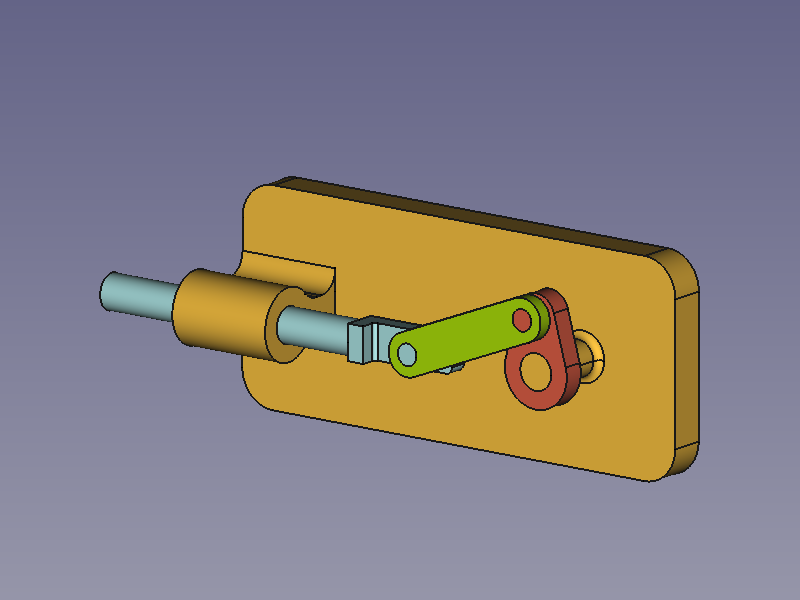
크랭크 슬라이더 조립품
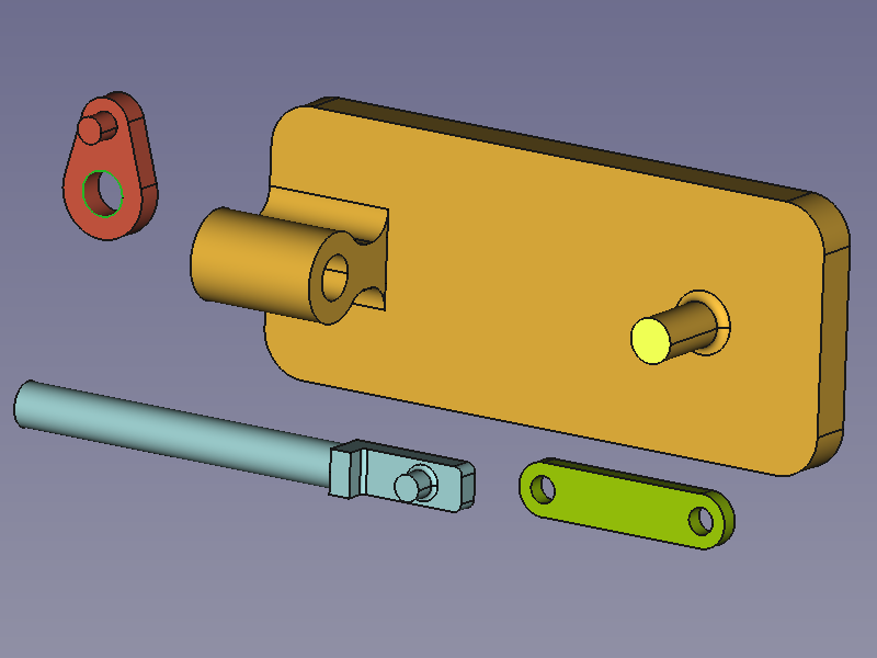
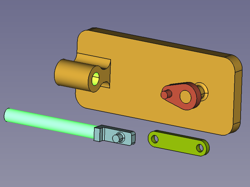
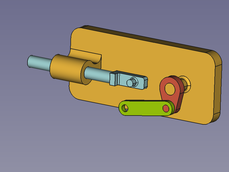
제작할 어셈블리는 베이스, 슬라이더 로드, 크랭크, 커넥팅 로드의 네 부분으로 구성됩니다. 각 부분은 네 개의 조인트로 연결됩니다.
Assembled parts: Base (amber), Slider Rod (light blue), Crank (red), Connecting Rod (green)
부품 준비
이 예에서는 모든 부품과 어셈블리가 하나의 문서에 생성됩니다.
The cylindrical geometries of the objects are either parallel or perpendicular, the rest of the shapes is not relevant for this example unless there are clashes. With this in mind you can model your own objects or create them with the Python code below. The code will create a new document with the four objects (simpler than in the images). Just copy-paste the following lines in the Python Console:
import FreeCAD as App
import FreeCADGui as Gui
import Part

doc = App.newDocument()

box1 = Part.makeBox(140, 40, 7, App.Vector(0, -20, 0))
cyl1 = Part.makeCylinder(4, 8, App.Vector(120, 0, 7))
box2 = Part.makeBox(20, 12, 10, App.Vector(5, -6, 7))
cyl2 = Part.makeCylinder(6, 20, App.Vector(25, 0, 17), App.Vector(-1, 0, 0))
cyl3 = Part.makeCylinder(4, 20, App.Vector(25, 0, 17), App.Vector(-1, 0, 0))
shape = box1.fuse([cyl1, box2, cyl2]).removeSplitter().cut(cyl3)
base = doc.addObject("Part::Feature", "Base")
base.Shape = shape

box1 = Part.makeBox(4, 12, 12, App.Vector(-12, -6, 0))
box2 = Part.makeBox(14, 12, 4, App.Vector(-8, -6, 0))
cyl1 = Part.makeCylinder(4, 8, App.Vector(0, 0, 4))
cyl2 = Part.makeCylinder(4, 88, App.Vector(-12, 0, 6),App.Vector(-1, 0, 0))
shape = box1.fuse([box2, cyl1, cyl2]).removeSplitter()
slider_rod = doc.addObject("Part::Feature", "SliderRod")
slider_rod.Shape = shape
slider_rod.Placement.Base = App.Vector(100, -40, 0)

cyl1 = Part.makeCylinder(7.5, 4)
box1 = Part.makeBox(15, 30, 4, App.Vector(-7.5, 0, 0))
cyl2 = Part.makeCylinder(7.5, 4, App.Vector(0, 30, 0))
cyl3 = Part.makeCylinder(4, 6, App.Vector(0, 30, 4))
cyl4 = Part.makeCylinder(4, 4)
shape = cyl1.fuse([box1, cyl2]).removeSplitter().fuse(cyl3).cut(cyl4)
crank = doc.addObject("Part::Feature", "Crank")
crank.Shape = shape
crank.Placement.Base = App.Vector(125, -70, 0)

cyl1 = Part.makeCylinder(6, 4)
box1 = Part.makeBox(50, 12, 4, App.Vector(0, -6, 0))
cyl2 = Part.makeCylinder(6, 4, App.Vector(50, 0, 0))
cyl3 = Part.makeCylinder(4, 4)
cyl4 = Part.makeCylinder(4, 4, App.Vector(50, 0, 0))
shape = cyl1.fuse([box1, cyl2]).removeSplitter().cut(cyl3.fuse(cyl4))
connecting_rod = doc.addObject("Part::Feature", "ConnectingRod")
connecting_rod.Shape = shape
connecting_rod.Placement.Base = App.Vector(25, -70, 0)

mat = base.ViewObject.ShapeAppearance[0]
mat.DiffuseColor = (0.80, 0.60, 0.15, 0.0)
base.ViewObject.ShapeAppearance = (mat,)

mat = slider_rod.ViewObject.ShapeAppearance[0]
mat.DiffuseColor = (0.55, 0.70, 0.70, 0.0)
slider_rod.ViewObject.ShapeAppearance = (mat,)

mat = crank.ViewObject.ShapeAppearance[0]
mat.DiffuseColor = (0.70, 0.30, 0.20, 0.0)
crank.ViewObject.ShapeAppearance = (mat,)

mat = connecting_rod.ViewObject.ShapeAppearance[0]
mat.DiffuseColor = (0.55, 0.70, 0.0, 0.0)
connecting_rod.ViewObject.ShapeAppearance = (mat,)

doc.recompute()
view = Gui.ActiveDocument.ActiveView
view.viewIsometric()
view.fitAll()
어셈블리 추가
With the New Assembly tool add an assembly to the document.
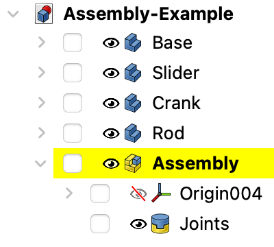
Tree View of Parts and Assembly
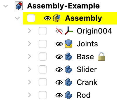
부품을 어셈블리로 옮기기
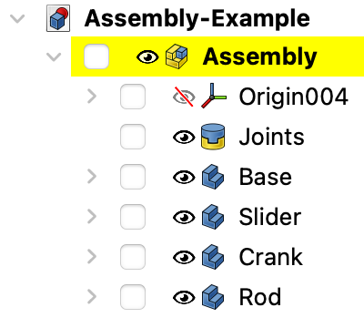
In the Tree View drag and drop the parts on the Assembly object. They can now be handled by the Assembly's solver.
The Parts are in the Assembly container now
Ground a part
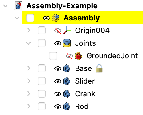
To keep the assembly at the desired position, the base part should be locked, or grounded as it is called here. Select the Base in the Tree View or in the 3D View and use the Toggle Grounded tool. This fixes the position of the Base in relation to the local coordinate system (LCS) of the Assembly container. A GroundedJoint object is added to the Joints container.
Expand the Joints container to find the GroundedJoint object
Alternative: Insert Link
Instead of the two steps mentioned above it is also possible to use the Component tool to place objects inside an assembly. The first object automatically becomes the grounded part. So you need to start with the Base object. The tool creates links and the original objects remain outside the assembly. To avoid confusion it is advisable to make them invisible.
조인트 적용
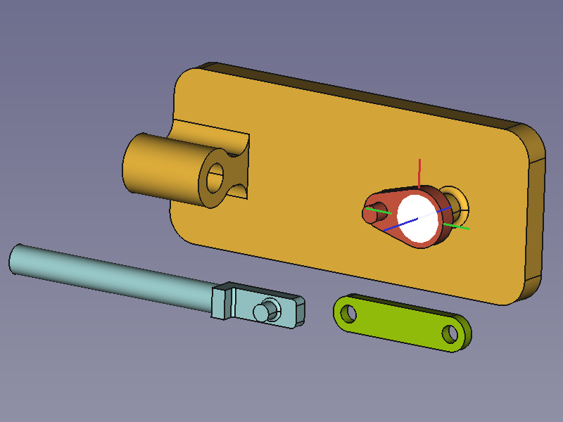
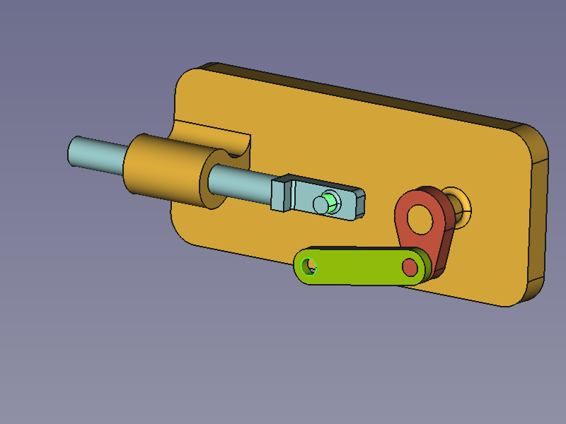
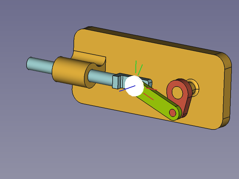
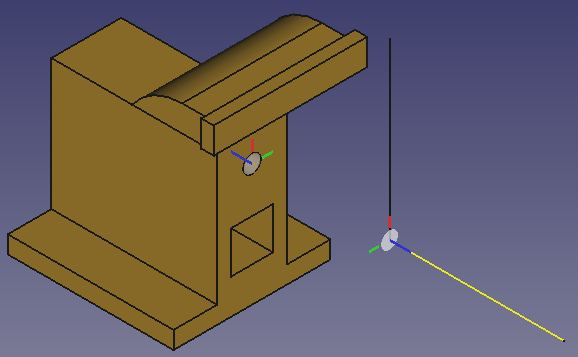
A joint connects exactly two elements of different parts. They can optionally be selected before the desired joint tool is invoked (any number of selected elements other than two results in an empty selection). The elements define the position and orientation of a LCS represented by a filled circle on the local XY-plane and three lines along the local X- (red), Y- (green), and Z-axis (blue).
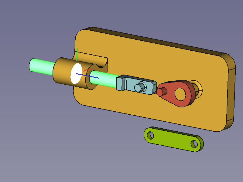
- 베이스와 크랭크 사이의 회전 조인트
Selected elements + Revolute Joint → rearranged Crank
크랭크는 마우스 왼쪽 버튼을 사용하여 움직이세요. 피벗을 중심으로 회전만 가능합니다.
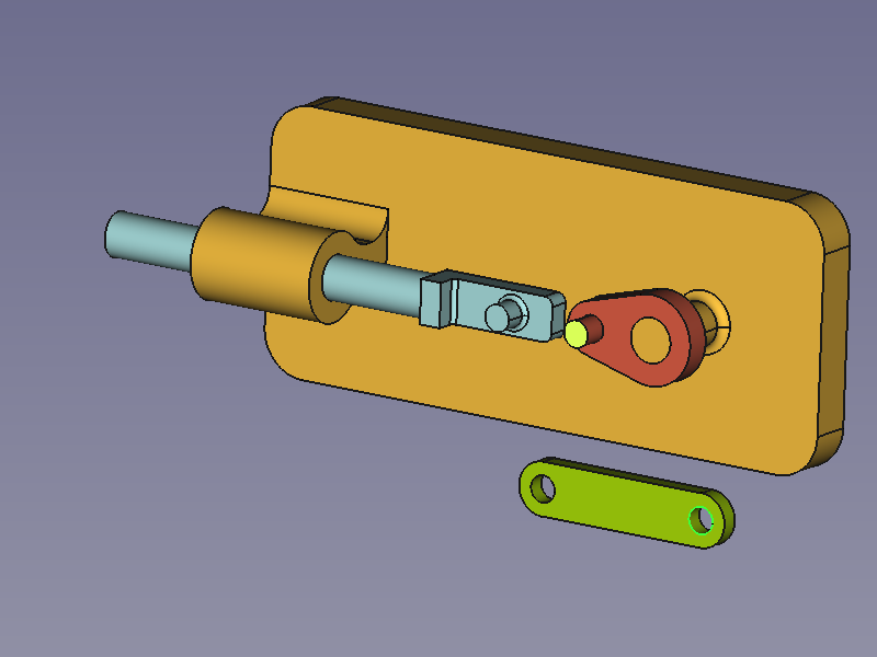
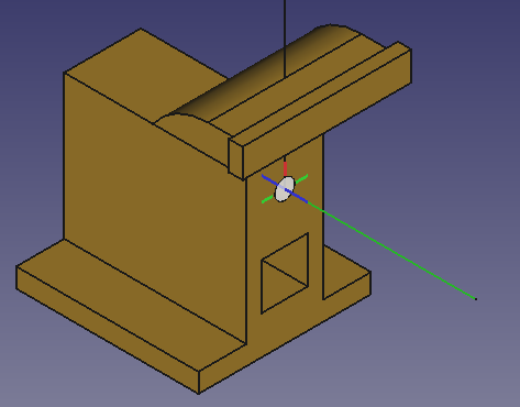
- A Slider joint between Base and Slider Rod
Selected elements + Slider Joint → rearranged Slider Rod
슬라이더로드를 마우스 왼쪽 버튼으로 이동하세요. 중심선을 따라서만 이동이 가능합니다.
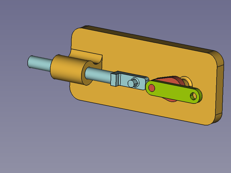
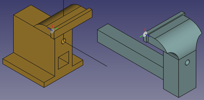
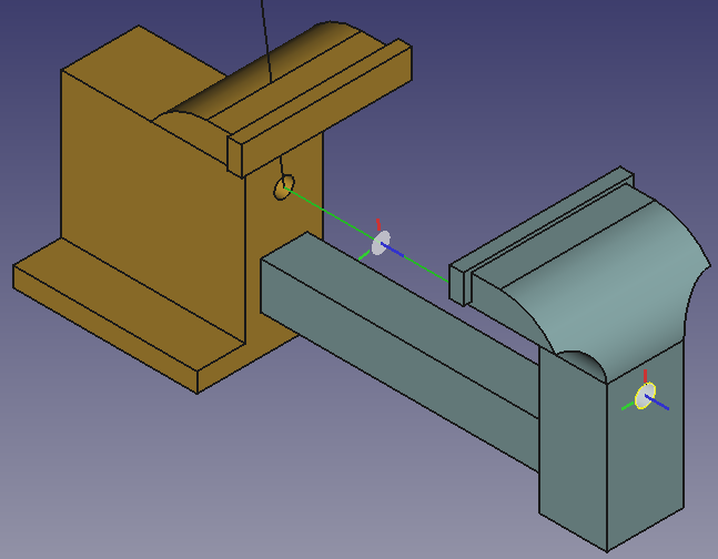
- A Revolute joint between Crank and Connecting Rod
Selected elements + Revolute Joint → rearranged Connecting Rod
크랭크는 마우스 왼쪽 버튼을 사용하여 움직이세요. 피벗을 중심으로 회전만 가능합니다.
If there are several joints in a line we have to help the solver find a sensible solution.
If required, click and drag the parts into an easier to compute position.
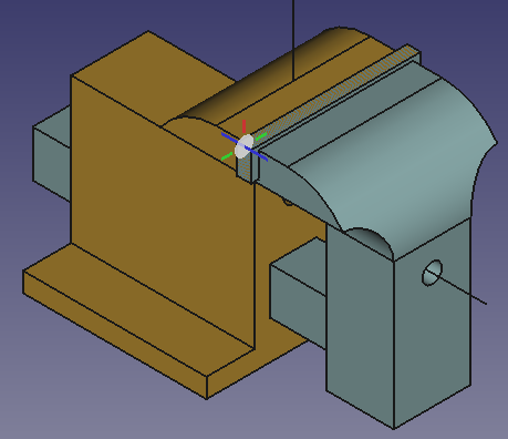
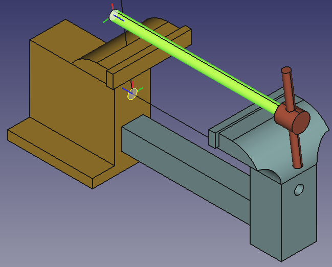
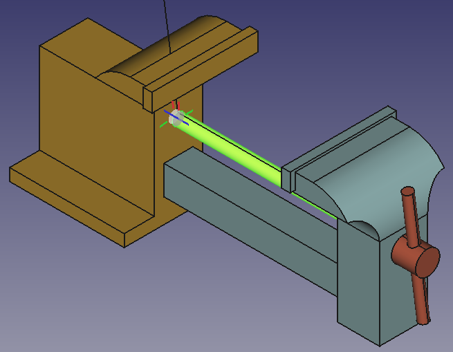
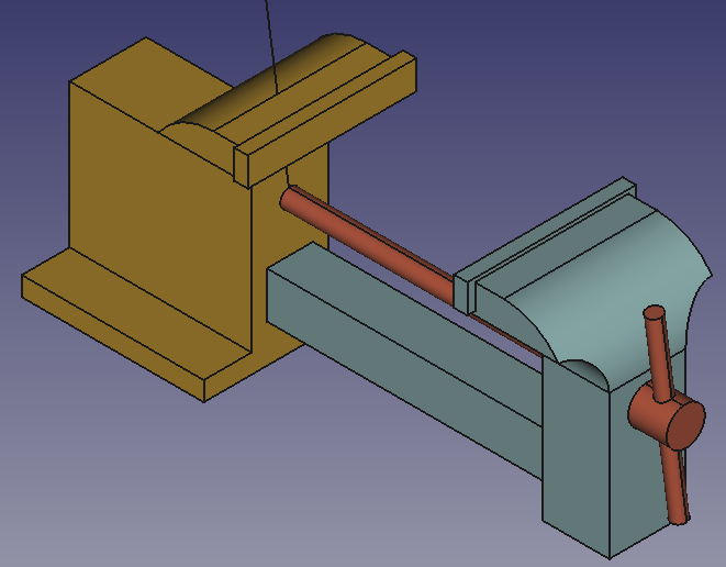
- A Cylindrical joint between Connecting Rod and Slider Rod
Selected elements + Cylindrical Joint → finished Assembly
완성된 조립품에서 마우스 포인터를 사용하여 사용된 조인트에 따라 부품을 드래그합니다.
참고
The pin of the Slider Rod is redundantly orientated. Its centerline is parallel to the pin of the Base through the kinematic chain from Base via Crank and Connecting Rod, i.e. its local Z-Axis cannot rotate around any X- or Y-axis. The Slider joint also prevents the rotation of its Z-Axis around two local axes and so results in two redundantly constrained degrees of freedom. A Cylindrical joint instead of the Slider joint would only lock one rotation resulting in only a single redundantly constrained degree of freedom.
크랭크를 돌리세요
To control the layout of the assembly by the angle between the Base and the Crank we have to change the Revolute joint between them to a Fixed joint. To do so double-click the Revolute object in the Tree View. In the dialog change Revolute to Fixed and change the Rotation value as desired (the movement should follow the mouse wheel action).
Note that a joint type change will change the joint's Label, but not its Name. In this case the Label is changed to "Fixed".
To animate the assembly we can change the Rotation (Offset1.Angle) of the Fixed joint with Python code. Just copy-paste the following lines in the Python Console:
import math
import FreeCAD as App
import FreeCADGui as Gui

actuator = App.ActiveDocument.getObjectsByLabel("Fixed")[0]

for angle in range(0, 361, 10):
    # A full rotation of the Crank in steps of 10°
    actuator.Offset1.Rotation.Angle = math.radians(angle)
    App.ActiveDocument.recompute()
    Gui.updateGui()
The end of the range must be greater than 360 to also include this angle as a valid result.
범용 조인트의 예
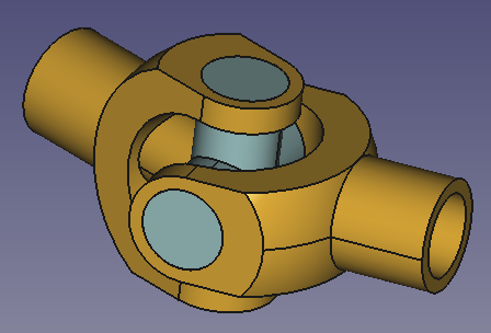
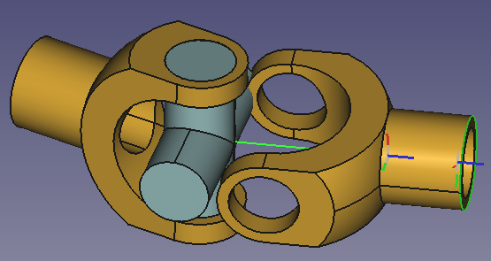
유니버설 조인트 어셈블리
In this example a universal joint is created.
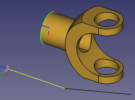
The assembly consists of three solid parts: two identical Forks and a Cross. Two additional non solid elements, Axle1 and Axle2, representing the angled axles, are also needed. The axles and the solid parts are connected with several joints.
부품 준비
In this example all parts and the assembly are created in one document.
The Python code below will create a new document with four objects (only 1 Fork). Just copy-paste the following lines in the Python Console:
import math
import FreeCAD as App
import FreeCADGui as Gui
import Part

doc = App.newDocument()

axle1 = doc.addObject("Part::Line", "Axle1")
axle1.X2 = -80
axle1.Y2 = 0
axle1.Z2 = 0

axle2 = doc.addObject("Part::Line", "Axle2")
axle2.X2 = 80
axle2.Y2 = 0
axle2.Z2 = 0
axle2.Placement.Rotation.Angle = math.radians(20)

sph1 = Part.makeSphere(50, App.Vector(0, 0, 0), App.Vector(-1, 0, 0), 0, 90, 360)
box1 = Part.makeBox(50, 40, 80, App.Vector(-50, -20, -40))
cyl1 = Part.makeCylinder(20, 80, App.Vector(0, 0, -40))
cyl2 = Part.makeCylinder(20, 80, App.Vector(0, 0, 0), App.Vector(-1, 0, 0))
cyl3 = Part.makeCylinder(30, 60, App.Vector(0, -30, 0), App.Vector(0, 1, 0))
box2 = Part.makeBox(30, 60, 60, App.Vector(0, -30, -30))
cyl4 = Part.makeCylinder(15, 80, App.Vector(0, 0, -40))
cyl5 = Part.makeCylinder(15, 80, App.Vector(0, 0, 0), App.Vector(-1, 0, 0))
shape = sph1.common(box1).fuse([cyl1, cyl2]).cut(cyl3.fuse([box2, cyl4, cyl5]))
fork = doc.addObject("Part::Feature", "Fork")
fork.Shape = shape.removeSplitter()
fork.Placement.Base = App.Vector(0, 100, 0)

cyl1 = Part.makeCylinder(15, 80, App.Vector(0, 0, -40))
cyl2 = Part.makeCylinder(15, 80, App.Vector(0, -40, 0), App.Vector(0, 1, 0))
shape = cyl1.fuse([cyl2])
cross = doc.addObject("Part::Feature", "Cross")
cross.Shape = shape.removeSplitter()
cross.Placement.Base = App.Vector(70, 100, 0)

mat = fork.ViewObject.ShapeAppearance[0]
mat.DiffuseColor = (0.80, 0.60, 0.15, 0.0)
fork.ViewObject.ShapeAppearance = (mat,)

mat = cross.ViewObject.ShapeAppearance[0]
mat.DiffuseColor = (0.55, 0.70, 0.70, 0.0)
cross.ViewObject.ShapeAppearance = (mat,)

doc.recompute()
view = Gui.ActiveDocument.ActiveView
view.viewIsometric()
view.fitAll()
축의 각도 변경
The angle between the axles is set to 20 degrees. If you want to change this value select Axle2 and change the Placement.Angle property. This property must be changed before moving Axle2 into the assembly.
Warning: parts may collide if the angle is too large.
어셈블리 추가
With the New Assembly tool add an assembly to the document.
축을 어셈블리로 이동
In the Tree View drag and drop the axles on the Assembly object.
Ground the axles
Select the two axles in the Tree View and use the Toggle Grounded tool.
축을 어셈블리로 이동
For the other objects we will use the Component tool:
- Invoke the tool.
- In the dialog that opens click the Cross object once, and the Fork object twice.
- Press the OK button.
- Make the objects outside the assembly invisible.
- If the objects inside the assembly overlap too much you can drag them to a new position.
Apply joints
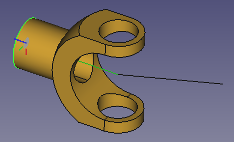
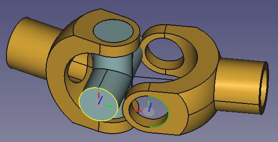
- A Revolute joint between Axle1 and Fork001
Selected elements + Revolute Joint + Offset of +40mm or -40mm → rearranged Fork001
If you invoke the tool first and then select the elements, you can click near the correct endpoint of Axle1 to avoid having to enter an offset.
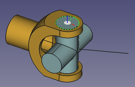
- A Cylindrical joint between Fork001 and Cross001
Selected elements + Cylindrical Joint → rearranged Cross001
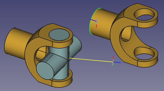
- A Cylindrical joint between Axle2 and Fork002
Selected elements + Cylindrical Joint → rearranged Fork002
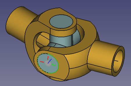
- A Cylindrical joint between Cross001 and Fork002
Selected elements + Cylindrical Joint → rearranged Cross001 and Fork002
유니버셜 조인트 구동
The universal joint can be driven by moving Fork001 with the left mouse.
If you want to check the situation at distinct rotation angles do the following:
- Change the Cylindrical joint between Axle1 and Fork001 to a Fixed joint.
- Select the Offset1.Angle property of the Fixed joint and roll the mouse wheel.
- The universal joint may be positioned to any angle.
예시 바이스
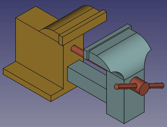
바이스 조립
In this example a vise is created.
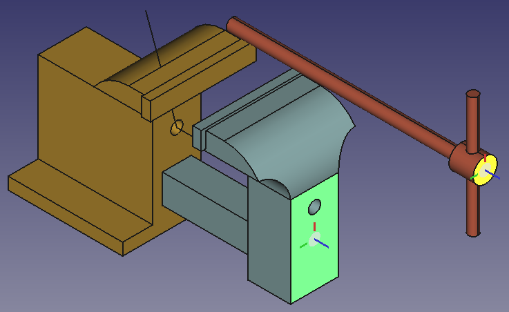
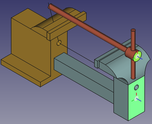
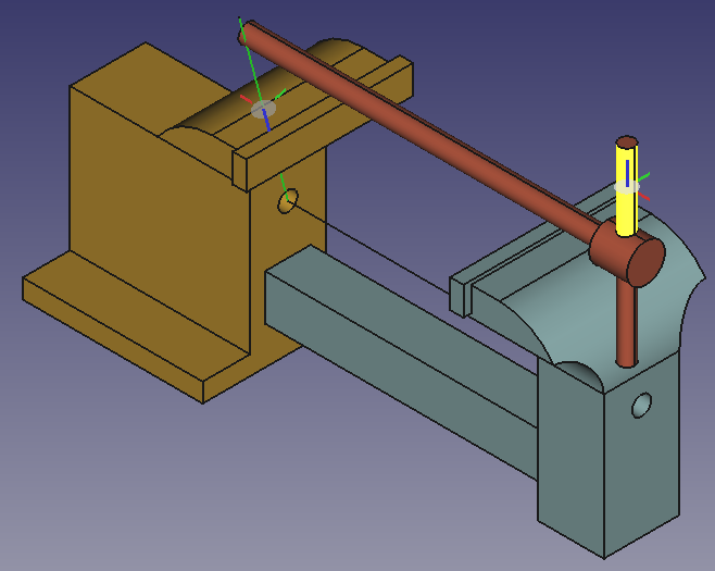
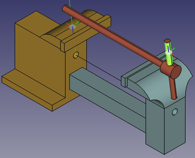
The assembly consists of three solid parts: a fixed and a movable jaw and a screw with a lever. One additional non solid element, a crank, is also needed. The crank and the solid parts are connected with several joints.
A Screw Joint couples the translation of a part with a Slider Joint to the rotation of a part with a Revolute Joint. The screw part shall make both a translation and a rotation movement hence it must be a part with a Cylindrical Joint. In this assembly, the screw part will be coupled to the movable jaw with a Distance Joint, to the non solid crank with a Parallel Joint, and to the fixed jaw with a Cylindrical Joint.
부품 준비
In this example all parts and the assembly are created in one document.
The Python code below will create a new document with four objects. Just copy-paste the following lines in the Python Console:
import math
import FreeCAD as App
import FreeCADGui as Gui
import Part

doc = App.newDocument()

box1 = Part.makeBox(95, 40, 75, App.Vector(0, -20, -22))
cyl1 = Part.makeCylinder(35, 80, App.Vector(0, -40, 53), App.Vector(0, 1, 0), 90)
box2 = Part.makeBox(20, 80, 30, App.Vector(-20, -40, 58))
cyl2 = Part.makeCylinder(15, 80, App.Vector(-15, -40, 58), App.Vector(0, 1, 0), 90)
box3 = Part.makeBox(5, 80, 15, App.Vector(-20, -40, 58))
box4 = Part.makeBox(35, 24, 24, App.Vector(0, -12, -12))
box5 = Part.makeBox(60, 34, 69, App.Vector(35, -17, -19))
cyl3 = Part.makeCylinder(20, 55, App.Vector(-20, -40, 53), App.Vector(1, 0, 0))
cyl4 = Part.makeCylinder(20, 55, App.Vector(-20, 40, 53), App.Vector(1, 0, 0))
cyl5 = Part.makeCylinder(5, 35, App.Vector(0, 0, 38), App.Vector(1, 0, 0))
box6 = Part.makeBox(7, 88, 15, App.Vector(-22, -44, 75))
box7 = Part.makeBox(95, 90, 10, App.Vector(0, -45, -32))
shape = box1.fuse([cyl1, box2, box6, box7]).cut(cyl2.fuse([box3, cyl3, cyl4, cyl5, box4, box5]))
fixedJaw = doc.addObject("Part::Feature", "FixedJaw")
fixedJaw.Shape = shape.removeSplitter()
fixedJaw.Placement.Rotation.Axis = App.Vector(0, 0, 1)
fixedJaw.Placement.Rotation.Angle = math.radians(180)

box1 = Part.makeBox(35, 40, 75, App.Vector(0, -20, -22))
cyl1 = Part.makeCylinder(35, 80, App.Vector(0, -40, 53), App.Vector(0, 1, 0), 90)
box2 = Part.makeBox(20, 80, 30, App.Vector(-20, -40, 58))
cyl2 = Part.makeCylinder(15, 80, App.Vector(-15, -40, 58), App.Vector(0, 1, 0), 90)
box3 = Part.makeBox(160, 24, 24, App.Vector(-160, -12, -12))
box4 = Part.makeBox(5, 80, 15, App.Vector(-20, -40, 58))
box5 = Part.makeBox(160, 18, 18, App.Vector(-160, -9, -9))
cyl3 = Part.makeCylinder(20, 55, App.Vector(-20, -40, 53), App.Vector(1, 0, 0))
cyl4 = Part.makeCylinder(20, 55, App.Vector(-20, 40, 53), App.Vector(1, 0, 0))
cyl5 = Part.makeCylinder(5, 35, App.Vector(0, 0, 38), App.Vector(1, 0, 0))
box6 = Part.makeBox(7, 88, 15, App.Vector(-22, -44, 75))
shape = box1.fuse([cyl1, box2, box3, box6]).cut(cyl2.fuse([box4, cyl3, cyl4, box5, cyl5]))
movableJaw = doc.addObject("Part::Feature", "MovableJaw")
movableJaw.Shape = shape.removeSplitter()
movableJaw.Placement.Base = App.Vector(150, 100, 0)

cyl1 = Part.makeCylinder(5, 190, App.Vector(0, 0, 0), App.Vector(1, 0, 0))
cyl2 = Part.makeCylinder(10, 20, App.Vector(190, 0, 0), App.Vector(1, 0, 0))
cyl3 = Part.makeCylinder(4, 100, App.Vector(200, 0, -50), App.Vector(0, 0, 1))
shape = cyl1.fuse([cyl2, cyl3])
leverScrew = doc.addObject("Part::Feature", "LeverScrew")
leverScrew.Shape = shape.removeSplitter()
leverScrew.Placement.Base = App.Vector(150, -100, 0)

wire1 = Part.makePolygon([App.Vector(0, 0, 100), App.Vector(0, 0, 0), App.Vector(100, 0, 0)])
crank = doc.addObject("Part::Feature", "Crank")
crank.Shape = wire1
crank.Placement.Base = App.Vector(0, -100, 0)

mat = fixedJaw.ViewObject.ShapeAppearance[0]
mat.DiffuseColor = (0.80, 0.60, 0.15, 0.0)
fixedJaw.ViewObject.ShapeAppearance = (mat,)

mat = movableJaw.ViewObject.ShapeAppearance[0]
mat.DiffuseColor = (0.55, 0.70, 0.70, 0.0)
movableJaw.ViewObject.ShapeAppearance = (mat,)

mat = leverScrew.ViewObject.ShapeAppearance[0]
mat.DiffuseColor = (0.70, 0.30, 0.20, 0.0)
leverScrew.ViewObject.ShapeAppearance = (mat,)

doc.recompute()
view = Gui.ActiveDocument.ActiveView
view.viewIsometric()
view.fitAll()
어셈블리 추가
With the New Assembly tool add an assembly to the document.
Move the parts into the assembly container
In the Tree View drag and drop the parts on the Assembly object. They can now be handled by the Assembly's solver.
Ground a part
To keep the assembly at the desired position, the FixedJaw part should be locked, or grounded as it is called here. Select the FixedJaw in the Tree View or in the 3D View and use the Toggle Grounded tool. A GroundedJoint object is added to the Joints container.
Apply joints
- A Revolute joint between FixedJaw and Crank
Selected elements + Revolute Joint → rearranged Crank
- A Slider joint between FixedJaw and MovableJaw
Selected elements + Slider Joint → rearranged MovableJaw
Set the Min length to -77 mm and the Max length to -7 mm. This limits the opening of the vise to 70 mm.
The next three joints are necessary to force the LeverScrew to: translate like the MovableJaw, rotate like the Crank, and rotate around the main axis.
- A Distance joint between LeverScrew and MovableJaw
Selected elements + Distance Joint → rearranged LeverScrew
두 면을 선택하세요. 거리 값을 20mm로 설정하세요.
- A Parallel joint between LeverScrew and Crank
Selected elements + Parallel Joint → rearranged LeverScrew
- A Cylindrical joint between LeverScrew and FixedJaw
Selected elements + Cylindrical Joint → rearranged LeverScrew
- A Screw joint between MovableJaw and Crank
Selected elements (LeverScrew invisible) + Screw Joint → complete vise mechanism (LeverScrew visible)
If necessary make the LeverScrew invisible during selection.
피치 반지름을 5mm로 설정합니다.
바이스를 돌리세요
The vise can be driven by moving Crank or MovableJaw with the left mouse.
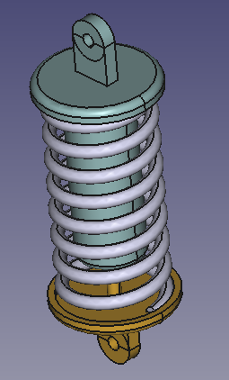
Example shock absorber
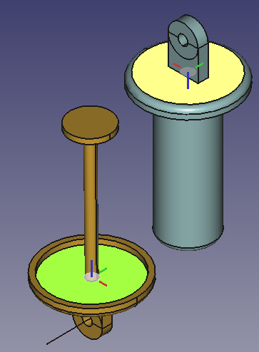
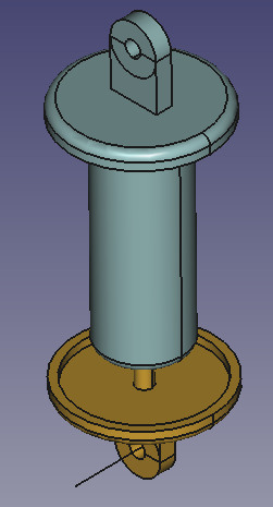
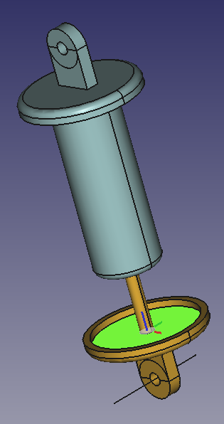
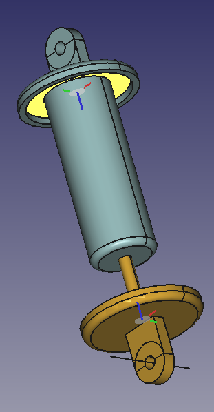
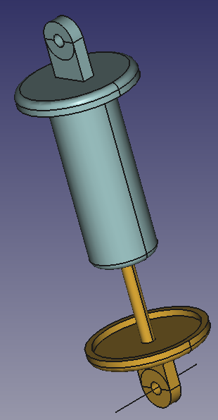
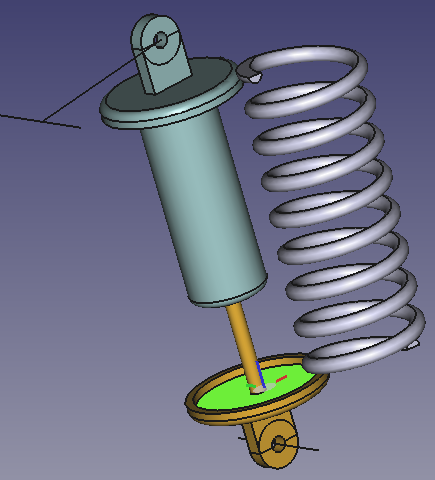
Assembly of a shock absorber
In this example a shock absorber is created.
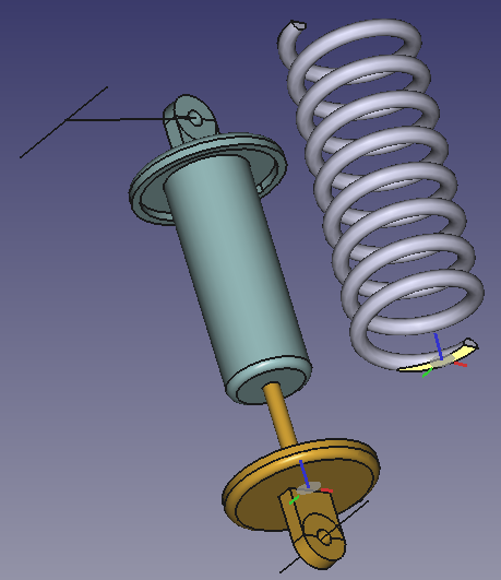
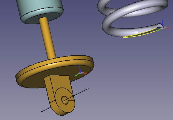
The assembly consists of three solid parts: a piston, a cylinder and a spring. Three additional non solid elements, two axles and a rod are also needed. All parts are connected with several joints.
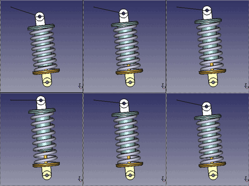
The hinge of the piston rotates around Axle2, while the hinge of the cylinder moves on an arc of circle centered on Axle1. The non solid Rod is used for this movement. The length of the Rod is the radius of the arc.
Prepare parts
The Python code below will create a new document with 6 objects. Create a new macro and copy-paste the code below in the Python editor (not in the Python Console). Then run the macro.
The code below cannot be run from the Python Console because the spring must be a Part::FeaturePython object defined by of a class with the callback functions execute() and onChanged(). Only then can its height be changed via a property.
import math
import FreeCAD as App
import FreeCADGui as Gui
import Part

doc = App.newDocument()

class Spring():
    def __init__(self, spring):
        spring.addProperty("App::PropertyLength", "Height", "Spring", "Height of the helix").Height = 200.0
        spring.Proxy = self
        spring.ViewObject.Proxy = 0

    def execute(self, spring):
        helix = Part.makeHelix(spring.Height/8.5, spring.Height, 35)
        startPnt = helix.Edges[0].Curve.value(0)
        section = Part.Wire([Part.Circle(startPnt, App.Vector(0, 1, 0), 5).toShape()])
        hel1 = helix.makePipeShell([section], True, True)
        box1 = Part.makeBox(80, 80, 10, App.Vector(-40, -40, -10))
        box2 = Part.makeBox(80, 80, 10, App.Vector(-40, -40, spring.Height))
        shape = hel1.cut(box1).cut(box2)
        spring.Shape = shape

    def onChanged(self, spring, prop):
        if prop == "Height":
            self.execute(spring)

spring = doc.addObject("Part::FeaturePython", "Spring")
Spring(spring)
spring.Placement.Base = App.Vector(0, 100, 0)

axle1 = doc.addObject("Part::Line", "Axle1")
axle1.X2 = 0
axle1.Y2 = 80
axle1.Z2 = 0

axle2 = doc.addObject("Part::Line", "Axle2")
axle2.X2 = 0
axle2.Y2 = 80
axle2.Z2 = 0
axle2.Placement.Base = App.Vector(120, 0, -250)

rod = doc.addObject("Part::Line", "Rod")
rod.X2 = 100
rod.Y2 = 0
rod.Z2 = 0
rod.Placement.Base = App.Vector(0, -50, 0)

cyl1 = Part.makeCylinder(40, 10,App.Vector(0, 0, -5))
tor1 = Part.makeTorus(40, 5)
cyl2 = Part.makeCylinder(45, 5)
box1 = Part.makeBox(30, 10, 30,App.Vector(-15, -5, -35))
cyl3 = Part.makeCylinder(15, 10, App.Vector(0, -5, -35), App.Vector(0, 1, 0))
cyl4 = Part.makeCylinder(40, 5)
cyl5 = Part.makeCylinder(5, 10,App.Vector(0, -5, -35), App.Vector(0, 1, 0))
cyl6 = Part.makeCylinder(5, 130)
cyl7 = Part.makeCylinder(20, 5,App.Vector(0, 0, 130))
shape = cyl1.fuse([tor1,cyl2, box1, cyl3]).cut(cyl4.fuse([cyl5])).fuse([cyl6, cyl7])
piston = doc.addObject("Part::Feature", "Piston")
piston.Shape = shape.removeSplitter()
piston.Placement.Base = App.Vector(200, 100, -200)

cyl1 = Part.makeCylinder(40, 10,App.Vector(0, 0, -5))
tor1 = Part.makeTorus(40, 5)
cyl2 = Part.makeCylinder(45, 5)
box1 = Part.makeBox(30, 10, 30,App.Vector(-15, -5, -35))
cyl3 = Part.makeCylinder(15, 10,App.Vector(0, -5, -35), App.Vector(0, 1, 0))
cyl4 = Part.makeCylinder(40, 5)
cyl5 = Part.makeCylinder(5, 10,App.Vector(0, -5, -35), App.Vector(0, 1, 0))
cyl6 = Part.makeCylinder(25, 130)
tor2 = Part.makeTorus(20, 5,App.Vector(0, 0, 130))
cyl7 = Part.makeCylinder(20, 135)
cyl8 = Part.makeCylinder(20, 130)
cyl9 = Part.makeCylinder(5, 135)
shape = cyl1.fuse([tor1, cyl2, box1, cyl3]).cut(cyl4.fuse([cyl5])).fuse([cyl6, tor2, cyl7]).cut(cyl8.fuse([cyl9]))
cylinder = doc.addObject("Part::Feature", "Cylinder")
cylinder.Shape = shape.removeSplitter()
cylinder.Placement.Rotation.Axis = App.Vector(0, 1, 0)
cylinder.Placement.Rotation.Angle = math.pi
cylinder.Placement.Base = App.Vector(100, 100, 0)

mat = piston.ViewObject.ShapeAppearance[0]
mat.DiffuseColor = (0.80, 0.60, 0.15, 0.0)
piston.ViewObject.ShapeAppearance = (mat,)

mat = cylinder.ViewObject.ShapeAppearance[0]
mat.DiffuseColor = (0.55, 0.70, 0.70, 0.0)
cylinder.ViewObject.ShapeAppearance = (mat,)

doc.recompute()
view = Gui.ActiveDocument.ActiveView
view.viewIsometric()
view.fitAll()
어셈블리 추가
With the New Assembly tool add an assembly to the document.
부품을 조립 용기로 옮기세요
In the Tree View drag and drop the parts on the Assembly object. They can now be handled by the Assembly's solver.
두 축을 접지합니다
To keep the assembly at the desired position, the two axles should be locked, or grounded as it is called here. Select the two axles in the Tree View or in the 3D View and use the Toggle Grounded tool. Two GroundedJoint objects are added to the Joints container.
조인트 적용
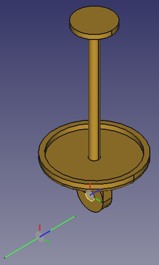
- A Revolute joint between Axle2 and Piston
Revolute Joint + Selected elements → rearranged Piston
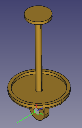
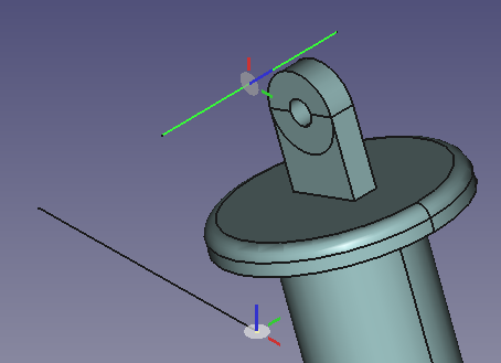
- 피스톤과 실린더 사이의 슬라이더 조인트
Slider Joint + Selected elements → rearranged and moved Cylinder
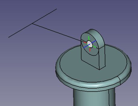
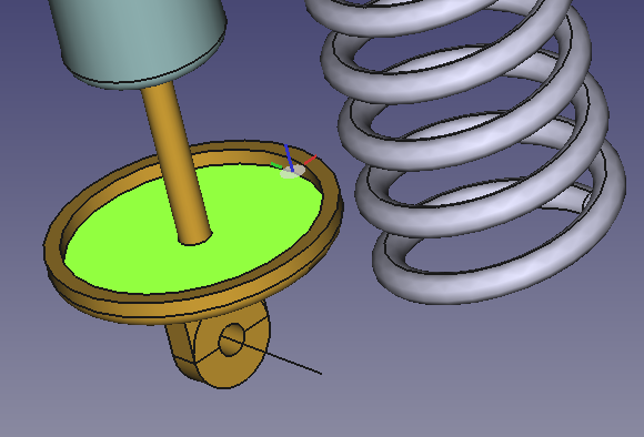
면을 선택하기 전에 좌표계의 위치를 확인하세요. 각 면의 중앙에 있어야 합니다.
실린더를 드래그하여 피스톤과 실린더 사이에 뚜렷한 차이를 만드세요. 스프링 지지면이 보여야 합니다.
- 피스톤과 실린더 사이의 거리 조인트
Distance Joint + Selected faces → rearranged Cylinder Distance set to 200 mm
거리 값을 200mm로 설정합니다.
다음 두 개의 관절은 실린더의 힌지를 원호를 따라 움직이게 하는 데 필요합니다.
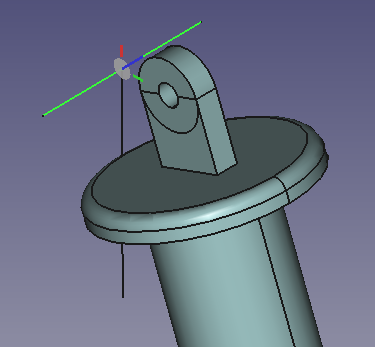
- Axle1과 Rod 사이의 원통형 조인트
Cylindrical Joint + Selected elements → rearranged Rod
끝점을 선택하여 좌표계의 Z축(파란색)이 막대에 수직인지 확인하세요.
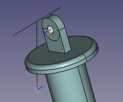
- 로드와 실린더 사이의 회전 조인트
Revolute Joint + Selected elements → rearranged Cylinder
다시 한번 좌표계의 Z축(파란색)이 막대에 수직인지 확인하세요.
이 조인트에 문제가 발생할 수 있습니다. 문제가 발생하면 다음을 시도해 보세요.
- 조인트를 삭제합니다.
- 정면 뷰로 전환합니다.
- 피스톤을 드래그하여 어셈블리를 회전하고, 실린더의 힌지 구멍 중심이 로드에 오도록 로드를 회전합니다.
- 조인트를 다시 생성합니다.
다음 두 개의 조인트는 스프링을 지지면에 고정하는 데 필요합니다.
- 스프링과 피스톤 사이의 평행 조인트
Parallel Joint + Selected faces → rearranged Spring
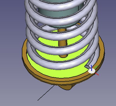
피스톤 지지면의 중심과 스프링 바닥면의 중심을 선택합니다. 거리 값은 0으로 유지합니다.
- 스프링과 피스톤 사이의 고정 조인트
Fixed Joint + Selected elements → rearranged Spring
피스톤에서 실린더 솔기의 아래쪽 정점을 선택하고 스프링에서 모서리 정점을 선택합니다.
- 표현식을 사용하여 Distance 조인트의 거리 속성을 스프링의 Height 속성에 연결합니다.
- 트리 뷰에서 스프링을 선택합니다.
- 높이 속성 필드에서 파란색 아이콘
을 선택합니다.
- 표현식 편집기에 다음을 입력합니다:
<<Distance>>.Distance
쇼바를 구동하세요
이렇게 하려면 트리 뷰에서 Distance 객체를 두 번 클릭하고 Distance 속성을 변경합니다. 문서를 다시 계산합니다. 스프링의 길이가 변경됩니다.
- Assembly: New Assembly, Component, New Part, Solve Assembly, Exploded View, Simulation, Bill of Materials
- Joints: Toggle Grounded, Fixed Joint, Revolute Joint, Cylindrical Joint, Slider Joint, Ball Joint, Distance Joint, Parallel Joint, Perpendicular Joint, Angle Joint, Rack and Pinion Joint, Screw Joint, Gears Joint, Belt Joint
- Preferences: Preferences
- Getting started
- Installation: Download, Windows, Linux, Mac, Additional components, Docker, AppImage, Ubuntu Snap
- Basics: About FreeCAD, Interface, Mouse navigation, Selection methods, Object name, Preferences, Workbenches, Document structure, Properties, Help FreeCAD, Donate
- Help: Tutorials, Video tutorials
- Workbenches: Std Base, Assembly, BIM, CAM, Draft, FEM, Inspection, Material, Mesh, OpenSCAD, Part, PartDesign, Points, Reverse Engineering, Robot, Sketcher, Spreadsheet, Surface, TechDraw, Test Framework
- Hubs: User hub, Power users hub, Developer hub
