TechDraw LengthDimension/ko
|
기술도면 길이 치수 |
| Menu location |
|---|
| 기술도면→ 치수 → 길이 치수 삽입 |
| Workbenches |
| 기술도면 작업대 |
| Default shortcut |
| None |
| Introduced in version |
| - |
| See also |
| 기술도면 수평 치수, 기술도면 수직 치수 |
설명
기술도면 길이치수 도구는 보기에 선형 치수를 추가합니다. 치수는 두 점 사이의 거리, 직선 모서리의 길이, 두 모서리 사이의 수직 거리, 또는 점과 모서리 사이의 수직 거리가 될 수 있습니다.

두 지점에서 가져온 길이 치수
용법
- Select the points and/or edges which define your measurement. The geometry may be selected in the 3D View (first two options) or in the drawing (all options):
- Select two points.
- Select a single straight edge.
- Select two edges. If both edges are straight they must be parallel. This will produce a perpendicular dimension if an endpoint of one of the edges has a perpendicular projection on the other edge (the resultant point must lie on the actual edge). If multiple solutions are possible, the endpoint that is closest to its projected point is used. If there is no valid perpendicular projection, the dimension will be the distance between the nearest endpoints of the edges.
- Select a point and an edge. This will produce a perpendicular dimension. In 0.21 and below the dimension will only be perpendicular if the point has a perpendicular projection on the actual edge. Else the dimension will be the distance between the point and the nearest endpoint of the edge.
- If you have selected geometry in the 3D View: add the correct TechDraw View to the selection by selecting it in the Tree View.
- There are several ways to invoke the tool:
- introduced in 1.0: If the Dimensioning tools preference is set to
Single tool(default): press the down arrow to the right of the
 button and select the
  Length Dimension option from the dropdown.
 - If this preference has a different value (and in 0.21 and below): press the Length Dimension button.
- Select the TechDraw → Dimensions → Length Dimension option from the menu.
- introduced in 1.0: If the Dimensioning tools preference is set to
- A dimension is added to the View.
- The dimension may be dragged to the desired position.
- If needed, add tolerances as described on this page.
3D 측정 표시
The dimension will initially display the projected measurement (i.e. as shown in the drawing). If required, and if the dimension is based on 3D references, it can be changed to the actual 3D measurement by changing its 데이터Measure Type property to True. To base a dimension on 3D references select geometry from the 3D View at creation time, or use the ![]() TechDraw DimensionRepair tool to update existing dimensions.
TechDraw DimensionRepair tool to update existing dimensions.
Change properties
To change the properties of a dimension object either double-click it in the drawing or in the Tree View. This will open the Dimension task panel.
치수 대화 상자

치수 대화 상자는 다음과 같은 설정을 제공합니다.
Dimension
- Number of decimals: Changes the number of decimals in the next input field.
- Format specifier: How the dimension value will be formatted. By default the specifier is
%.xwwherexis the number of decimals and trailing zeros are removed. For the formatting syntax see this Wikipedia page. There is also an additional%.xfformat that prints the number of decimals without removing trailing zeros.
- Arbitrary text: If checked, the dimension is replaced by the content of the Format specifier field.
- Reference: If checked, the dimension value is enclosed in parenthesis to indicate it is for reference only.
허용 오차(Tolerancing)
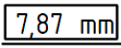
- 이론적으로 정확함: 체크하면 치수가 이론적으로 정확하게 지정됩니다. 따라서 허용 오차가 없어야 합니다. 치수는 값 주위에 사각틀이 표시됩니다:
- 동일 허용 오차: 체크 시, 위치수 허용 오차와 아래치수 허용 오차가 동일하며, 위치수 허용 오차의 음수 값이 아래치수 허용 오차로 사용됩니다. 표시 방법은
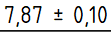 또는
또는 입니다.
입니다.
- 위 치수 허용 오차: 치수가 더 커질 수 있는 양.
- 아래 치수 허용 오차: 치수가 더 작아질 수 있는 양.
- Overtolerance format specifier: How the overtolerance value will be formatted. By default the specifier is
%.xwwherexis the number of decimals. For the formatting syntax see this Wikipedia page.
- Undertolerance format specifier: How the undertolerance value will be formatted. By default the specifier is
%.xwwherexis the number of decimals. For the formatting syntax see this Wikipedia page.
- Arbitrary tolerance text: If checked, the tolerances are replaced by the content of the Overtolerance format specifier and Undertolerance format specifier fields.
Display Style
- Flip arrowheads: Flips the direction of the dimension line arrows. By default they are inside the dimension line/arc and point outwards.
- Color: The color for lines and text.
- Font size: The dimension text size.
- Drawing style: The standard (and its style) according to which the dimension is drawn. See the property Standard And Style for details.
Lines
- Override angles: If checked, the usual angles for the dimension line and extension lines will be overridden by the specified values.
- Dimension line angle: Override value for angle of dimension line with view X-axis (in degrees).
- Use Default: Set dimension line angle to the usual angle.
- Use Selection: Set dimension line angle to match the angle of the selected edge (or 2 vertices) in the view.
- Extension line angle: Override value for angle of extension lines with view X-axis (in degrees).
- Use Default: Set extension line angle to the usual angle.
- Use Selection: Set extension line angle to match the angle of the selected edge (or 2 vertices) in the view.
제한사항
치수 대상체는 "위상적 명명 문제(TNP)"에 취약합니다. 즉, 3D 형상을 수정하면 모형의 면과 모서리 이름이 내부적으로 변경될 수 있습니다. 치수가 모서리에 부착된 후 수정되는 경우 치수가 깨질 수 있습니다. 일반적으로, 투상된 2D 치수를 실제 3D 대상체와 동기화하는 것은 불가능합니다.
따라서 3D 모형이 더 이상 수정되지 않을 때 치수를 추가하는 것이 좋습니다.
보충 설명
- Edge selection. Edges can be difficult to select. You can adjust the selection area for edges by changing the Edge Fuzz preference.
- Decimal places. Dimensions use the global decimal places setting by default. This can be changed in the preferences or by changing the FormatSpec property.
속성
Data
Base
- 데이터References 2D (
LinkSubList): The 2D drawing View object(s) on which the measurement is based. Used if 데이터Measure Type isProjected. - 데이터References 3D (
LinkSubList): The 3D object(s) on which the measurement is based. Used if 데이터Measure Type isTrue. - 데이터Type (
Enumeration): Length, radius, diameter, etc. Not normally manipulated by the end user. - 데이터Measure Type (
Enumeration): How the measurement is performed.
True- based on 3D geometry.Projected- based on 2D drawing View geometry.
- 데이터Theoretical Exact (
Bool): Specifies a theoretically exact (or basic) dimension.
false- a common dimension by default, possibly with tolerances.true- a theoretical value. As such, it shall not bear any tolerances. The dimension will be displayed by a frame around the value:
- 데이터Equal Tolerance (
Bool): If over- and undertolerance are equal. Then the negated value of the overtolerance is used as undertolerance.
true- the negated value of the 데이터Over Tolerance is used as 데이터Under Tolerance. The display will befalse- the 데이터Under Tolerance is taken into account. The display will be
- 데이터Over Tolerance (
QuantityConstraint): The amount by which the dimension may be larger. - 데이터Under Tolerance (
QuantityConstraint): The amount by which the dimension may be smaller. - 데이터Inverted (
Bool): Marks whether the dimension represents a common or an inverted value.
false- the ordinary value is used. For length it is a positive number, for angle the oblique value (0° - 180°).true- the inverted value is used. For length a negative number, for angle the reflex value (180° - 360°).
- 데이터X (
Distance): Horizontal position of the dimension text relative to the View. - 데이터Y (
Distance): Vertical position of the dimension text relative to the View. - 데이터 (Hidden)Lock Position (
Bool): Locks the position of the dimension text whentrue. - 데이터 (Hidden)Rotation (
Angle): Read only. - 데이터 (Hidden)Scale Type (
Enumeration): Read only. - 데이터 (Hidden)Scale (
FloatConstant): Read only. - 데이터 (Hidden)Caption (
String): Not used.
Format
- 데이터Format Spec (
String): How the dimension value will be formatted. See Formatting. - 데이터Format Spec Over Tolerance (
String): Like 데이터Format Spec, but for overtolerances. - 데이터Format Spec Under Tolerance (
String): Like 데이터Format Spec, but for undertolerances. - 데이터Arbitrary (
Bool): Whether the dimension is replaced by the content of the Format Spec field.
false- the content of the Format Spec is used to format the actual dimensional value.true- the content of the Format Spec will be displayed as text instead of the dimension value.
- 데이터Arbitrary Tolerances (
Bool): Like 데이터Arbitrary, but for the tolerance.
Override
- 데이터Angle Override (
Bool): Whether the direction of dimension and extension lines is overridden.
false- the directions are computed as usual.true- the directions are overridden by LineAngle and ExtensionAngle property values.
- 데이터Line Angle (
Angle): Angle of dimension line with view X-axis (in degrees). - 데이터Extension Angle (
Angle): Angle of extension line(s) with view X-axis (in degrees).
References
- 데이터 (Hidden)Saved Geometry (
TopoShapeList): Reference geometry. introduced in 0.21
View
Base
- 보기Keep Label (
Bool): Not used. - 보기Stack Order (
Integer): Over or underlap relative to other drawing objects. introduced in 0.21
Dimension Format
- 보기Arrowsize (
Length): The size of the dimension arrows. introduced in 0.21 - 보기Color (
Color): Color for lines and text. - 보기Flip Arrowheads (
Bool): By default the value inside the dimension line/arc means the arrows pointing outwards. If placed outside the dimension line/arc, the arrows point inwards the dimension line/arc.
false- Let the direction of arrows to be selected automatically according to the rule above.true- Override the automatically chosen direction and force the opposite one.
- 보기Font (
Font): The name of the font to use for the dimension text. - 보기Fontsize (
Length): Dimension text size. - 보기Gap Factor ASME (
Float): Adjusts the gap between the dimension points and the start of the extension lines. The gap is this value times the line width. introduced in 0.21 - 보기Gap Factor ISO (
Float): Adjusts the gap between the dimension points and the start of the extension lines. The gap is this value times the line width. introduced in 0.21 - 보기Line Spacing Factor (
Float): Adjusts the gap between the dimension text and the dimension line. The gap is this value times the line width. introduced in 0.21 - 보기Line Width (
Length): Dimension line weight. - 보기Rendering Extent (
Enumeration): Rather universal property specifying how much space the dimension drawing may take up:
None- no lines or arrows are drawn, only the bare dimension value is displayed.Minimal- for lengths and angles a single headed line connecting the dimensional value and the end point's virtual extension line is drawn. The extension line itself is not added.- Diameters are rendered following
Confinedextent, radii followingReducedextent. Confined- for lengths and angles a double headed line (or arc) connecting the start and end point's virtual extension lines is drawn, though the extension lines themselves are not added.- Diameters are drawn with a minimal single headed line from dimensional value to the closest point on circle, radii as with
Reducedextent. Reduced- for lengths and angles a single headed line connecting the dimensional value and the end point's extension line is drawn along with the extension line itself.- Diameters are drawn with a single headed line from the center to the closest point on circle, radii with a minimal single headed line from dimensional value to the closest arc point.
Normal- the default value. For lengths and angles a double headed line (or arc) connecting the start and end point's extension lines is drawn, the extension lines themselves as well.- Diameters are drawn as double headed lines striking the center and connecting the closest and farthest points on the circle.
- Radii are drawn as a single headed line from center to the closest arc point.
Expanded- Only diameters support this value, rendering them in a horizontal or vertical length-like way. Other dimension types are rendered as withNormalextent.
- 보기Standard And Style (
Enumeration): Specifies the standard (and its style) according to which the dimension is drawn:
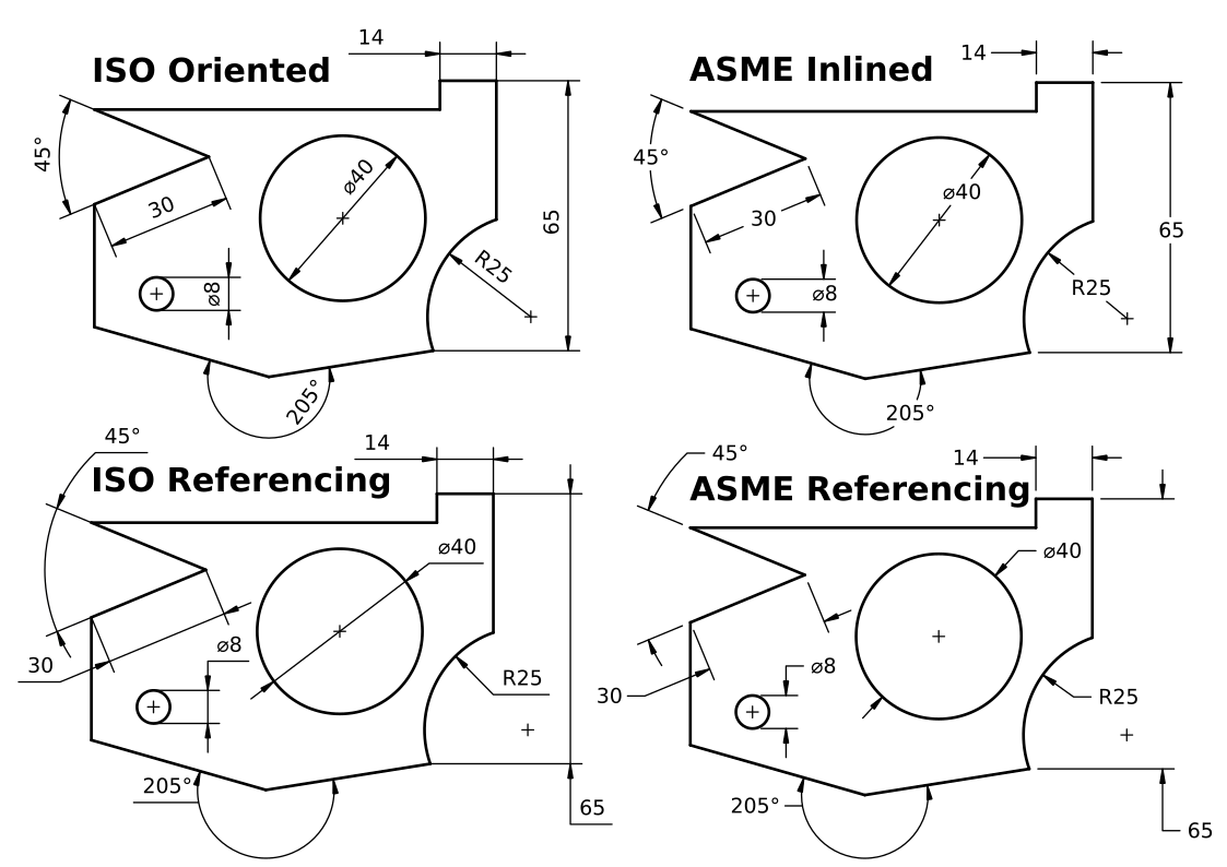
ISO Oriented- drawn according to the standard ISO 129-1, text is rotated to be parallel with the dimension line tangent.ISO Referencing- drawn in compliance with ISO 129-1, text is always horizontal, above the shortest possible reference line.ASME Inlined- drawn according to the standard ASME Y14.5M, text is horizontal, inserted in a break within the dimension line or arc.ASME Referencing- drawn in compliance with ASME Y14.5M, text is horizontal, short reference line is attached to one side's vertical center.

Scripting
See also: Autogenerated API documentation and FreeCAD Scripting Basics.
The Length Dimension tool can be used in macros and from the Python Console by using the following functions:
dim1 = FreeCAD.ActiveDocument.addObject("TechDraw::DrawViewDimension", "Dimension")
dim1.Type = "Distance"
dim1.References2D=[(view1, "Edge1")]
page.addView(dim1)
- Pages: Insert Default Page, Insert Page using Template, Update template fields, Redraw Page, Print All Pages, Export Page as SVG, Export Page as DXF
- Views:
- TechDraw views: Insert View, Insert Broken View, Insert Section View, Insert Complex Section View, Insert Detail View, Insert Projection Group, Insert Clip Group, Insert SVG Symbol, Insert Bitmap Image, Share View, Turn View Frames On/Off, Project Shape
- Views from other workbenches: Insert Active View, Insert Draft Workbench Object, Insert BIM Workbench Object, Insert Spreadsheet View
- Stacking: Move view to top of stack, Move view to bottom of stack, Move view up one level, Move view down one level
- Dimensions: Insert Dimension, Insert Length Dimension, Insert Horizontal Dimension, Insert Vertical Dimension, Insert Radius Dimension, Insert Diameter Dimension, Insert Angle Dimension, Insert 3-Point Angle Dimension, Insert Area Annotation, Create Arc Length Dimension, Insert Horizontal Extent Dimension, Insert Vertical Extent Dimension, Create Horizontal Chain Dimensions, Create Vertical Chain Dimensions, Create Oblique Chain Dimensions, Create Horizontal Coordinate Dimensions, Create Vertical Coordinate Dimensions, Create Oblique Coordinate Dimensions, Create Horizontal Chamfer Dimension, Create Vertical Chamfer Dimension, Insert Balloon Annotation, Insert Axonometric Length Dimension, Insert Landmark Dimension, Dimension Repair, Link Dimension to 3D Geometry
- Hatching: Hatch Face using Image File, Apply Geometric Hatch to Face,
- Annotations: Insert Annotation, Add Leaderline to View, Insert Rich Text Annotation, Add Cosmetic Vertex, Add Midpoint Vertices, Add Quadrant Vertices, Add Centerline to Faces, Add Centerline between 2 Lines, Add Centerline between 2 Points, Add Cosmetic Line Through 2 points, Add Cosmetic Circle, Change Appearance of Lines, Show/Hide Invisible Edges, Add Welding Information to Leader, Add Surface Finish Symbol, Add Hole or Shaft Tolerances
- Extensions:
- Attributes and modifications: Select Line Attributes, Cascade Spacing and Delta Distance, Change Line Attributes, Extend Line, Shorten Line, Lock/Unlock View, Position Section View, Position Horizontal Chain Dimensions, Position Vertical Chain Dimensions, Position Oblique Chain Dimensions, Cascade Horizontal Dimensions, Cascade Vertical Dimensions, Cascade Oblique Dimensions, Calculate the area of selected faces, Calculate the arc length of selected edges, Customize format label
- Centerlines and threading: Add Circle Centerlines, Add Bolt Circle Centerlines, Add Cosmetic Thread Hole Side View, Add Cosmetic Thread Hole Bottom View, Add Cosmetic Thread Bolt Side View, Add Cosmetic Thread Bolt Bottom View, Add Cosmetic Intersection Vertex(es), Add an offset vertex, Add Cosmetic Circle, Add Cosmetic Arc, Add Cosmetic Circle 3 Points, Add Cosmetic Parallel Line, Add Cosmetic Perpendicular Line
- Dimensions: Insert '⌀' Prefix, Insert '□' Prefix, Insert 'n×' Prefix, Remove Prefix, Increase Decimal Places, Decrease Decimal Places
- Miscellaneous: Remove Cosmetic Object
- Additional: Line Groups, Templates, Hatching, Geometric dimensioning and tolerancing, Preferences
- Getting started
- Installation: Download, Windows, Linux, Mac, Additional components, Docker, AppImage, Ubuntu Snap
- Basics: About FreeCAD, Interface, Mouse navigation, Selection methods, Object name, Preferences, Workbenches, Document structure, Properties, Help FreeCAD, Donate
- Help: Tutorials, Video tutorials
- Workbenches: Std Base, Assembly, BIM, CAM, Draft, FEM, Inspection, Material, Mesh, OpenSCAD, Part, PartDesign, Points, Reverse Engineering, Robot, Sketcher, Spreadsheet, Surface, TechDraw, Test Framework
- Hubs: User hub, Power users hub, Developer hub