TechDraw Geometric dimensioning and tolerancing
Concept
The main purpose of a technical drawing is that others understand what the designer created with what tolerances AND how to manufacture the design. Since most parts have to fit to assemblies, also the geometric relations to other parts are important. To achieve this, the system of Geometric Dimensioning and Tolerancing (GD&T) was developed.
Take for example this part:
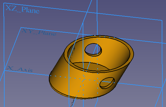
In the application an axis should be put through the 2 holes of the part. That means we have to specify the following things
- The diameter of the holes and their positions.
- That the holes are along a certain axis that is not perpendicular to the XZ base plane.
- That the axis part must have a certain straightness.
The straightness is important because a bent axis would not fit through the holes. The hole alignment is important because just drilling each hole at the given position without taking care of the axis, would lead to holes through which the axis will not fit. So just specifying the hole dimension and position is not sufficient. The first point is "classical" dimensioning while the 2 others are geometric information, thus GD&T comes into play. The example also makes clear that GD&T is essential to assure that parts fit well to assemblies.
If you are not familiar with the concept of GD&T, we highly recommend to learn about it now. For example a quick introduction is given in this video. For more like the concept of the "maximum material condition", have a look at this video. For details to all sorts of GD&T features, look around in the Internet. For example this YouTube channel provides some good explanations.
GD&T is defined in the standards ISO 1101 and ASME Y14.5.
TechDraws' capabilities to fulfill the common GD&T standards is limited (as of FreeCAD 0.20) but you can achieve already many things. This Wiki page explains what is implemented and what tricks can be used for non-implemented features. Note: this Wiki page is not about to teach GD&T!
Dimensioning
TechDraw provides several tools to create different types of dimension. Please have a look at the different dimensions on how to create and modify them.
Formatting
The default font for new dimension is determined by the preferences setting Label Font. The default font size is specified by the preferences setting Font Size.
Note: It is recommended to use a font in which the minus sign has the same width as the plus sign because this assured that tolerances will be formatted as proposed by the GD&T norms. Such a font is for example osifont that is part of all FreeCAD installations.
The default format for new dimension numbers depends on the preferences options Use Global Decimals and Alternate Decimals. This specifies the number of decimals, but in every case the dimension is a floating point number. For example if the setting is to have 2 decimals, the used format specifier is "%.2f" (floating point number with 2 decimals).
The number format can be changed:
- Either double-click on the dimension in the drawing or onto the dimension object in the model tree
- In the appearing dimension dialog the field Format Specifier contains the format specifier, so change it to what you need
The syntax of the format specifier is explained here. You can also use this online tool to see what formatting specifier will format numbers.
Examples:
- You use 2 decimals but for an angle you want to have only one decimal use the format specifier %.1f.
- You use 2 decimals but don't like that trailing zeroes are printed (you prefer 4 instead of 4.00). Then use this format specifier: %g. The 'g' will use the shortest possible output and thus it omits trailing zeroes. Moreover it will automatically switch to scientific notation if necessary.
With the property DataInverted you can make length dimensions negative and flip angles from the range 0 - 180° to the the reflex range 180° - 360°.
Setting the option Theoretically Exact in the dimension dialog will mark the dimension as theoretically exact by adding a frame around it.
You can use your own text instead of a formatted number by setting the option Arbitrary Text in the dimension dialog. Then the content of the field Format Specifier will be printed as dimension.
With the properties DataX and DataY you can change the horizontal and vertical position of the dimension text relative to the view. Alternatively you can change the position by dragging the dimension number or text.
Tolerances
Creation
- Create a dimension in your drawing
- Either double-click on the dimension in the drawing or onto the dimension object in the model tree
- In the appearing dimension dialog specify as Overtolerance the amount by which the dimension can be exceeded.
This will result in an equal tolerance like this: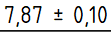
- If you have unequal tolerances, specify as Undertolerance the amount by which the dimension can be smaller and uncheck the option Equal Tolerance.
This will result in an unequal tolerance like this:
Deletion
To get rid of a tolerance, change Overtolerance and Undertolerance to each zero.
Formatting
The default font for new tolerances is the same than for dimensions. The default font size is specified by the preferences setting Tolerance Text Scale. This scale is a factor of the font size used for the dimension.
The default number format for new tolerances is by default the same format than for the dimension. It can be changed in the dimension dialog.
You can also use your own text instead of a formatted number by checking the option Arbitrary Tolerance Text in the dimension dialog. Then the content of Tolerance Format Specifier will be used as tolerance text.
Geometrical Tolerancing
Tolerances are created by using the Balloon feature of TechDraw. Since for most features a frame is required, it is helpful to change in the TechDraw preferences the Balloon Shape to Rectangle.
Tolerance indicator
The tolerance indicator of GD&T is a frame, also called "feature control frame". It can be created by using the Balloon feature of TechDraw:
- after adding a Balloon and if its shape is not already a frame, double-click on it in the model tree and set in the appearing dialog the Shape to Rectangle.
- add the corresponding Unicode character for the feature you need to the Balloon Text. (You can copy them from the reference tables below or use TechDraw ExtensionCustomizeFormat.)
- by adding the character '|' to the Text, you start a new indicator field.
There is no rule that defines if or how the tolerance indicator must have a leader line or not, so you can either:
- set the property Line Visible to False in the balloon dialog.
- set End Symbol to Filled Arrow or Dot.
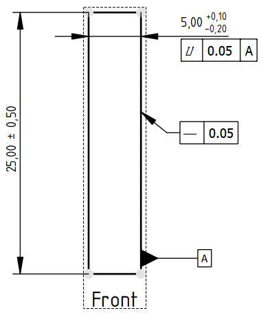
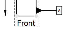
The example at the right side shows the two possible tolerance indicator layouts.
Datums
Datums in the GD&T sense of the meaning are surfaces your tolerance is relative to. They are created as Balloon:
- after adding a Balloon, set End Symbol to Filled Triangle in the balloon dialog.
- if the bubble shape is not already a frame, set Bubble Shape to Rectangle.
- drag the bubble with the mouse so that the triangle points away from the datum surface.
- since it is common to have a straight line for datums unless the datum surface is not perpendicular to X or Y, assure that either the properties DataX and DataOrigin X or DataY and DataOrigin Y are equal to get a straight Balloon line.
Symbol reference
To insert GD&T symbols TechDraw provides the Customize format label feature.
As reference, here are lists of characters to be used for geometric tolerancing:
| Type of control | Geometric characteristics | Symbol | Unicode character | Datum necessary | Notes |
|---|---|---|---|---|---|
| Form | Straightness | ||||
| Form | Flatness | ||||
| Form | Roundness | In older norms also called circularity. | |||
| Form | Cylindricity | ||||
| Form / Orientation / Location | Line profile | No datum necessary when used for form purpose | |||
| Form / Orientation / Location | Surface profile | No datum necessary when used for form purpose | |||
| Orientation | Parallelism | ||||
| Orientation | Perpendicularity | ||||
| Orientation | Angularity | ||||
| Location | Position | No datum necessary when working with norm ISO 5458. | |||
| Location | Concentricity / Coaxiality | Named concentricity when used for center points and coaxiality when used for median lines. In the norm ASME Y14.5 it was eliminated since the version from 2018. | |||
| Location | Symmetry | In the norm ASME Y14.5 from 2018, the symmetry was eliminated. | |||
| Run-out | Circular run-out | ||||
| Run-out | Total run-out |
| Symbol | Unicode character | Modifier | Notes |
|---|---|---|---|
 |
Free state | Applies only when part is otherwise restrained | |
 |
Least material condition (LMC) | Useful to maintain minimum wall thickness | |
 |
Maximum material condition (MMC) | Provides bonus tolerance only for a feature of size | |
 |
Projected tolerance zone | Useful on threaded holes for long studs | |
 |
Regardless of feature size (RFS) | Not part of the 1994 version. See para. A5, bullet 3. Also para. D3. Also, Figure 3-8. | |
 |
Tangent plane | Useful for interfaces where form is not required | |
 |
Continuous feature | Identifies a group of features that should be treated geometrically as a single feature | |
 |
Statistical tolerance | Appears in the 1994 version of the standard, assumes appropriate statistical process control. | |
 |
Unequal bilateral | Added in the 2009 version of the standard, and refers to unequal profile distribution. Number after this symbol indicates tolerance in the "plus material" direction. |
- Pages: Insert Default Page, Insert Page using Template, Update template fields, Redraw Page, Print All Pages, Export Page as SVG, Export Page as DXF
- Views:
- TechDraw views: Insert View, Insert Broken View, Insert Section View, Insert Complex Section View, Insert Detail View, Insert Projection Group, Insert Clip Group, Insert SVG Symbol, Insert Bitmap Image, Share View, Turn View Frames On/Off, Project Shape
- Views from other workbenches: Insert Active View, Insert Draft Workbench Object, Insert BIM Workbench Object, Insert Spreadsheet View
- Stacking: Move view to top of stack, Move view to bottom of stack, Move view up one level, Move view down one level
- Dimensions: Insert Dimension, Insert Length Dimension, Insert Horizontal Dimension, Insert Vertical Dimension, Insert Radius Dimension, Insert Diameter Dimension, Insert Angle Dimension, Insert 3-Point Angle Dimension, Insert Area Annotation, Create Arc Length Dimension, Insert Horizontal Extent Dimension, Insert Vertical Extent Dimension, Create Horizontal Chain Dimensions, Create Vertical Chain Dimensions, Create Oblique Chain Dimensions, Create Horizontal Coordinate Dimensions, Create Vertical Coordinate Dimensions, Create Oblique Coordinate Dimensions, Create Horizontal Chamfer Dimension, Create Vertical Chamfer Dimension, Insert Balloon Annotation, Insert Axonometric Length Dimension, Insert Landmark Dimension, Dimension Repair, Link Dimension to 3D Geometry
- Hatching: Hatch Face using Image File, Apply Geometric Hatch to Face,
- Annotations: Insert Annotation, Add Leaderline to View, Insert Rich Text Annotation, Add Cosmetic Vertex, Add Midpoint Vertices, Add Quadrant Vertices, Add Centerline to Faces, Add Centerline between 2 Lines, Add Centerline between 2 Points, Add Cosmetic Line Through 2 points, Add Cosmetic Circle, Change Appearance of Lines, Show/Hide Invisible Edges, Add Welding Information to Leader, Add Surface Finish Symbol, Add Hole or Shaft Tolerances
- Extensions:
- Attributes and modifications: Select Line Attributes, Cascade Spacing and Delta Distance, Change Line Attributes, Extend Line, Shorten Line, Lock/Unlock View, Position Section View, Position Horizontal Chain Dimensions, Position Vertical Chain Dimensions, Position Oblique Chain Dimensions, Cascade Horizontal Dimensions, Cascade Vertical Dimensions, Cascade Oblique Dimensions, Calculate the area of selected faces, Calculate the arc length of selected edges, Customize format label
- Centerlines and threading: Add Circle Centerlines, Add Bolt Circle Centerlines, Add Cosmetic Thread Hole Side View, Add Cosmetic Thread Hole Bottom View, Add Cosmetic Thread Bolt Side View, Add Cosmetic Thread Bolt Bottom View, Add Cosmetic Intersection Vertex(es), Add an offset vertex, Add Cosmetic Circle, Add Cosmetic Arc, Add Cosmetic Circle 3 Points, Add Cosmetic Parallel Line, Add Cosmetic Perpendicular Line
- Dimensions: Insert '⌀' Prefix, Insert '□' Prefix, Insert 'n×' Prefix, Remove Prefix, Increase Decimal Places, Decrease Decimal Places
- Miscellaneous: Remove Cosmetic Object
- Additional: Line Groups, Templates, Hatching, Geometric dimensioning and tolerancing, Preferences
- Getting started
- Installation: Download, Windows, Linux, Mac, Additional components, Docker, AppImage, Ubuntu Snap
- Basics: About FreeCAD, Interface, Mouse navigation, Selection methods, Object name, Preferences, Workbenches, Document structure, Properties, Help FreeCAD, Donate
- Help: Tutorials, Video tutorials
- Workbenches: Std Base, Assembly, BIM, CAM, Draft, FEM, Inspection, Material, Mesh, OpenSCAD, Part, PartDesign, Points, Reverse Engineering, Robot, Sketcher, Spreadsheet, Surface, TechDraw, Test Framework
- Hubs: User hub, Power users hub, Developer hub