TechDraw SectionView
|
|
| Menu location |
|---|
| TechDraw → TechDraw Views → Section View |
| Workbenches |
| TechDraw |
| Default shortcut |
| None |
| Introduced in version |
| - |
| See also |
| TechDraw ComplexSection, TechDraw View |
Description
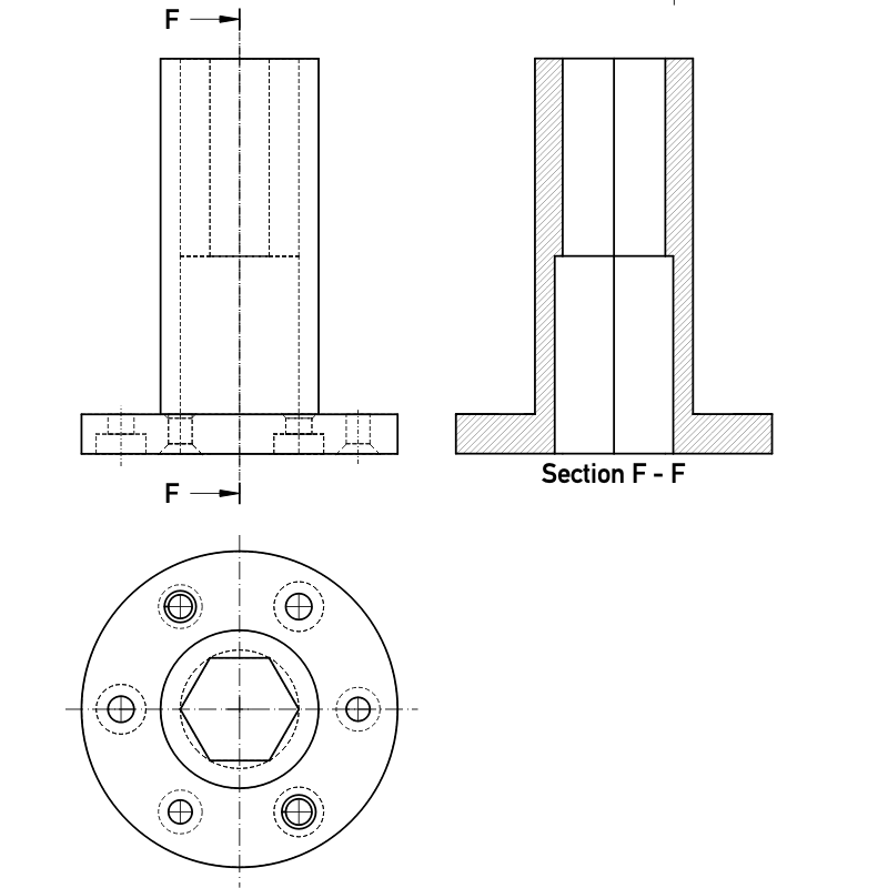
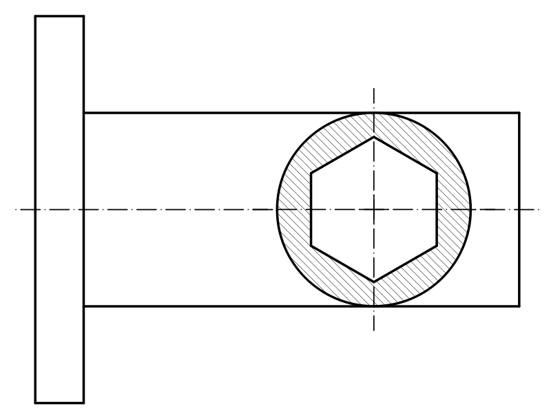
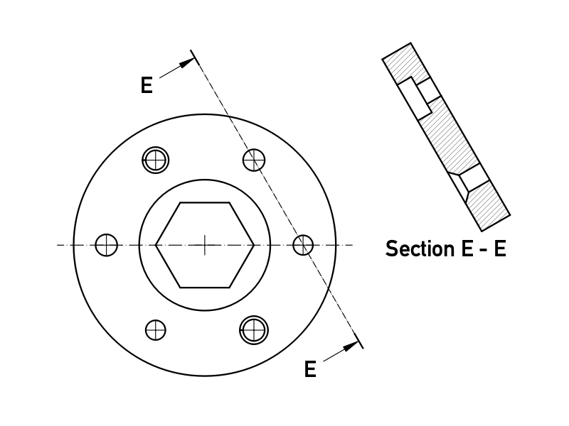
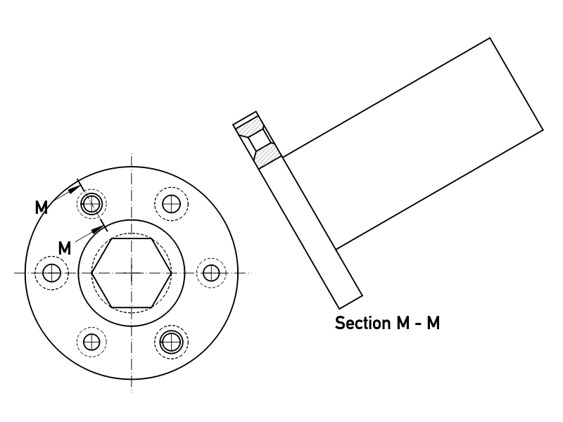
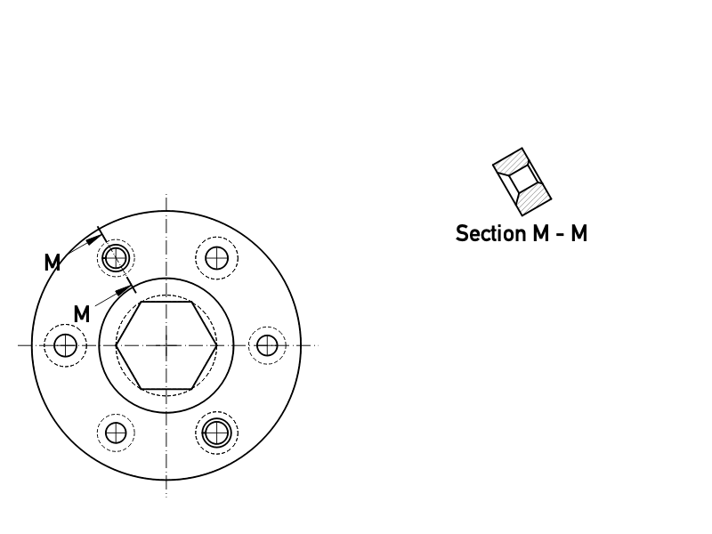
The TechDraw SectionView tool inserts a cross-section view based on an existing Part View.


Sectioning an already placed view, which shows the internal holes and a hatched cut surface.
The top image shows the ANSI arrow format.
The bottom image shows the ISO arrow format.
Usage
- Select a Part View in the 3D View or Tree View.
- There are several ways to invoke the tool:
- Press the
 Section View button.
 - Select the TechDraw → TechDraw Views → Section View option from the menu.
- Press the
- A task panel opens which will help calculate the various properties. Reasonable values for the view Direction are calculated, but these can be changed.

Task panel to define the sectional cut of a view
Properties
See also: Property View.
In the properties of the DataBase View you can change the appearance of the section line.
A Section View, formally a TechDraw::DrawViewSection object, is derived from a Part View, formally a TechDraw::DrawViewPart object, and inherits all its properties. It also has the following additional properties:
Data
Appearance
- DataSection Line Stretch (
FloatConstraint): Adjusts the length of the section line.1.0is normal length,1.1would be 10% longer,0.9would be 10% shorter. introduced in 1.0
Cut Operation
- DataFuse Before Cut (
Bool): Fuse the source shapes before performing the section cut. - DataTrim After Cut (
Bool): Additionally trim the resulting shape after the section cut to remove any unwanted pieces. introduced in 0.21 - DataUse Previous Cut (
Bool) Use the cut shape from the base view instead of the original object. introduced in 1.0
Cut Surface Format
- DataCut Surface Display (
Enumeration): Appearance of the cut surface. Options:Hide: Hides the cut surface, only the outline will be displayed.Color: Colors the cut surface using the setting of Cut Surface Color in the TechDraw preferences.SvgHatch: Hatches the section cut using a hatchPatHatch: Hatches the section cut using a geometric hatch
- DataFile Hatch Pattern (
File): Full path to SVG hatch pattern file. - DataFile Geom Pattern (
File): Full path to PAT pattern file. - DataSvg Included (
FileIncluded): Full path to the included SVG hatch pattern file. - DataPat Included (
FileIncluded): Full path to the included PAT pattern file. - DataName Geom Pattern (
String): Name of the PAT pattern to use. - DataHatch Scale (
Float): Hatch pattern size adjustment. - DataHatch Rotation (
Float): Rotation of hatch pattern in degrees counter-clockwise. introduced in 0.21 - Data (Hidden)Hatch Offset (
Vector): Hatch pattern offset. introduced in 0.21
Section
- DataSection Symbol (
String): The identifier for this section. - DataBase View (
Link): The view on which this section is based. - DataSection Normal (
Vector): A vector describing the direction normal to the cutting plane. - DataSection Origin (
Vector): A vector describing a point on the cutting plane. Typically the centroid of the original part. - DataSection Direction (
Enumeration): The direction in the Base View for this section. Options:Aligned,Right,Left,UporDown.
View
Cut Surface
- ViewCut Surface Color (
Color): Solid color for surface highlight. Used if DataCut Surface Display is set toColor. - View (Hidden)Show Cut Surface (
Bool): Show/hide the cut surface.
Surface Hatch
- ViewGeom Hatch Color (
Color): The color of the Geometric hath pattern. - ViewHatch Color (
Color): The color of the Svg hatch pattern. - View (Hidden)Hatch Cut Surface (
Bool): Hatch the cut surface. - ViewWeight Pattern (
Float): Line weight of the Geometric hatch pattern.
Notes
- Section Line Format: two section line formats are supported (as depicted above) and controlled by the Preference setting "Section line convention" on the General page. The
ANSIoption uses "pulling arrows" (also known as the "traditional format") and theISOoption uses "pushing arrows" (also known as the "reference arrow format"). - Fuse Before Cut: the section operation sometimes fails to cut the source shapes. If Fuse Before Cut is true, the source shapes are merged into a single shape before the section operation is attempted. If you encounter problems with the section operation, try flipping this value.
- Trim After Cut: the section cut operation sometimes leaves behind a portion of the source shape. If Trim After Cut is true, an additional cut operation is performed on the result of the first cut which should remove any unwanted pieces.
- Cut Surface Display: the cut surface can be hidden, painted in a solid color, hatched using an Svg pattern (default) or hatched using a PAT pattern. See Hatching.
Scripting
See also: Autogenerated API documentation and FreeCAD Scripting Basics.
A SectionView can be created with macros and from the Python Console by using the following functions:
doc = FreeCAD.ActiveDocument
box = doc.Box
page = doc.Page

view = doc.addObject("TechDraw::DrawViewPart", "View")
page.addView(view)
view.Source = box
view.Direction = (0, 0, 1)

section = doc.addObject("TechDraw::DrawViewSection", "Section")
page.addView(section)
section.Source = box
section.BaseView = view
section.Direction = (0, 1, 0)
section.SectionNormal = (-1, 0, 0)

doc.recompute()
Examples
For some more information about section views and some use cases, have a look at: TechDraw section examples.
![]()
- Page: New Page, New Page From Template, Update Template Fields, Redraw Page, Print All Pages, Export Page as SVG, Export Page as DXF
- TechDraw Views: New View, Broken View, Section View, Complex Section View, Detail View, Projection Group, Clip Group, Insert SVG, Bitmap Image, Share View, Project Shape
- Views From Other Workbenches: Active View, Draft View, BIM View, Spreadsheet View
- Dimensions: Dimension, Length Dimension, Horizontal Length Dimension, Vertical Length Dimension, Radius Dimension, Diameter Dimension, Angle Dimension, Angle Dimension From 3 Points, Area Annotation, Horizontal Extent Dimension, Vertical Extent Dimension, Repair Dimension References
- Hatching: Image Hatch, Geometric Hatch
- Symbols: Weld Symbol, Surface Finish Symbol, Hole/Shaft Fit
- Stacking: Stack Top, Stack Bottom, Stack Up, Stack Down
- Attributes/Modifications: Select Line Attributes, Cascade Spacing and Delta Distance, Change Line Attributes, Extend Line, Shorten Line, Toggle View Lock, Position Section View, Align Horizontal Chain Dimensions, Align Vertical Chain Dimensions, Align Oblique Chain Dimensions, Cascade Horizontal Dimensions, Cascade Vertical Dimensions, Cascade Oblique Dimensions, Area Annotation, Arc Length Annotation, Customize Format Label
- Centerlines/Threading: Circle Centerlines, Bolt Circle Centerlines, Cosmetic Thread Hole Side View, Cosmetic Thread Hole Bottom View, Cosmetic Thread Bolt Side View, Cosmetic Thread Bolt Bottom View, Cosmetic Intersection Vertices, Offset Vertex, Cosmetic 1 Point Circle, Cosmetic 2 Point Circle, Cosmetic 3 Point Circle, Cosmetic Arc, Cosmetic Parallel Line, Cosmetic Perpendicular Line
- Format/Organize Dimensions Horizontal Chain Dimension, Vertical Chain Dimension, Oblique Chain Dimension, Horizontal Coordinate Dimension, Vertical Coordinate Dimension, Oblique Coordinate Dimension, Horizontal Chamfer Dimension, Vertical Chamfer Dimension, Arc Length Dimension, Insert '⌀' Prefix, Insert '□' Prefix, Insert 'n×' Prefix, Remove Prefix, Increase Decimal Places, Decrease Decimal Places
- Annotations: Text Annotation, Rich Text Annotation, Balloon Annotation, Axonometric Length Dimension
- Add Lines: Leader Line, Centerline on Face, Centerline Between 2 Lines, Centerline Between 2 Points, Cosmetic Line Through 2 points, Edit Line Appearance, Toggle Edge Visibility
- Add Vertices: Cosmetic Vertex, Midpoint Vertices, Quadrant Vertices
- Miscellaneous: Remove Cosmetic Object
- Additional: Line Groups, Templates, Hatching, Geometric dimensioning and tolerancing, Preferences
- Getting started
- Installation: Download, Windows, Linux, Mac, Additional components, Docker, AppImage, Ubuntu Snap
- Basics: About FreeCAD, Interface, Mouse navigation, Selection methods, Object name, Preferences, Workbenches, Document structure, Properties, Help FreeCAD, Donate
- Help: Tutorials, Video tutorials
- Workbenches: Std Base, Assembly, BIM, CAM, Draft, FEM, Inspection, Material, Mesh, OpenSCAD, Part, PartDesign, Points, Reverse Engineering, Robot, Sketcher, Spreadsheet, Surface, TechDraw, Test Framework
- Hubs: User hub, Power users hub, Developer hub