Arch Site/es
|
|
| Ubicación en el Menú |
|---|
| Arquitectura → Ubicación |
| Entornos de trabajo |
| Arquitectura |
| Atajo de teclado por defecto |
| S I |
| Introducido en versión |
| - |
| Ver también |
| Arquitectura Piso, Arquitectura Edificio |
Descripción
El Arquitectura Ubicación es un objeto especial que combina propiedades de un objeto de grupo estándar de FreeCAD y objetos de Arch. Es particularmente adecuado para representar un sitio de proyecto completo o terreno. En trabajos arquitectónicos basados en IFC, se usa principalmente para organizar su modelo, al contener objetos Edificio. El sitio también se usa para administrar y mostrar un terreno físico, y puede calcular volúmenes de tierra para agregar o eliminar.
Utilización
- Opcionalmente, seleccionar uno o más objetos a ser incluidos en tu nueva ubicación
- Pulse el botón
Arquitectura Ubicación, o pulsar las teclas S y I
Opciones
- Después de la creación de una ubicación, puedes añadirle más objetos arrastrando y soltándolos en la vista en árbol o utilizando la herramienta
Arquitectura Añadir. Esto solo determina qué objeto forma parte del sitio determinado y no tiene ningún efecto en el terreno en sí.
- Puedes eliminar objetos de una ubicación arrastrando y soltándolos fuera en la vista de árbol o utilizando la herramienta
 Arquitectura Eliminar
 - Puede agregar un objeto de terreno editando la propiedad DatosTerreno del Sitio. El terreno debe ser una caparazón o superficie abierta.
- Puede agregar volúmenes para agregar o restar del terreno base, haciendo doble clic en el Sitio y agregando objetos a sus grupos Resta o Adiciones. Los objetos deben ser sólidos.
- La propiedad DatosVector Extrusión se puede usar para resolver algunos problemas que pueden aparecer al trabajar con sustracciones y adiciones. Para realizar esas adiciones / sustracciones, la superficie del terreno se extruye en un sólido, que luego se une / resta apropiadamente. Dependiendo de la topología del terreno, esta extrusión puede fallar con el vector de extrusión predeterminado. Por lo tanto, es posible que pueda solucionar el problema cambiando este a un valor diferente.
Propiedades
Data
Site
Datos
- DatosAddress: la calle y el número de este sitio
- DatosPostal Code: el código postal o postal de este sitio
- DatosCity: La ciudad de este sitio
- DatosCountry: El país de este sitio
- DatosLatitude: la latitud de este sitio
- DatosLongitude: la longitud de este sitio
- DatosUrl: una URL que muestra este sitio en un sitio web de mapas
- DatosProjected Area: el área de la proyección de este objeto en el plano XY
- DatosPerimeter: la longitud del perímetro de este terreno
- DatosAddition Volume: el volumen de tierra que se agregará a este terreno
- DatosSubtraction Volume: el volumen de tierra que se eliminará de este terreno
- DatosExtrusion Vector: un vector de extrusión para usar cuando se realizan operaciones booleanas
- DatosRemove Splitter: elimina los divisores de la forma resultante
- DatosDeclination: El ángulo entre el Norte verdadero y la dirección Norte en este documento, es decir, el eje Y. introducido en la versión 0.18 Esto significa que por defecto el Norte apunta al eje Y, y el Este al eje X; el ángulo se incrementa en sentido contrario a las agujas del reloj. Esta propiedad se conocía anteriormente como DatosDesviación Norte.
- DatosFichero EPW: Permite adjuntar un archivo EPW de la Ladybug EPW data website a este sitio. Esto es necesario para mostrar los diagramas de rosa de los vientos introducido en la versión 0.19
View
Compass
- VistaCompass (
Bool): Default isFalse. Shows or hides the compass. - VistaCompass Position (
Vector): The position of the compass relative to the site placement. - VistaCompass Rotation (
Angle): The rotation of the compass relative to the site. - VistaUpdate Declination (
Bool): Default isFalse. Update the declination value based on the compass rotation.
Site
- VistaOrientation (
Enumeration): Default isProject North. When set toTrue Norththe whole geometry will be rotated to match the true north of this site. - VistaSolar Diagram (
Bool): Default isFalse. Shows or hides the sun path diagram. See Solar and wind diagrams. - VistaSolar Diagram Color (
Color): The color of the sun path diagram. - VistaSolar Diagram Position (
Vector): The position of the sun path diagram. - VistaSolar Diagram Scale (
Float): The scale of the sun path diagram. - VistaWind Rose (
Bool): Default isFalse. Shows or hides the wind rose diagram (requires the EPW File data property filled, and the Ladybug Python module installed. See Solar and wind diagrams).
Flujo de trabajo típico
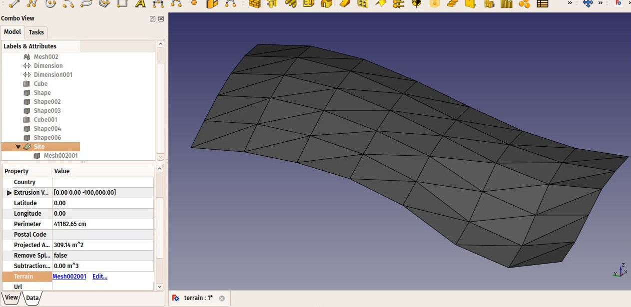
Comienza creando un objeto que represente tu terreno. Debe ser una superficie abierta, no un sólido. Por ejemplo, es fácil importar datos de malla, que se pueden convertir en una Forma de Parte desde el menú Pieza → Crear Forma desde Malla. A continuación, cree un objeto Sitio, y establezca su propiedad DatosTerreno a la Pieza que acabamos de crear:
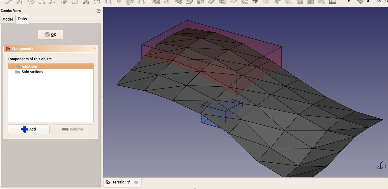
Cree algunos volúmenes (deben ser sólidos) que representen las áreas que desea que se excaven o rellenen. Haga doble clic en el objeto del Sitio en la Vista en árbol y agregue estos volúmenes a los grupos Adiciones o Restas. Haga clic en Aceptar.
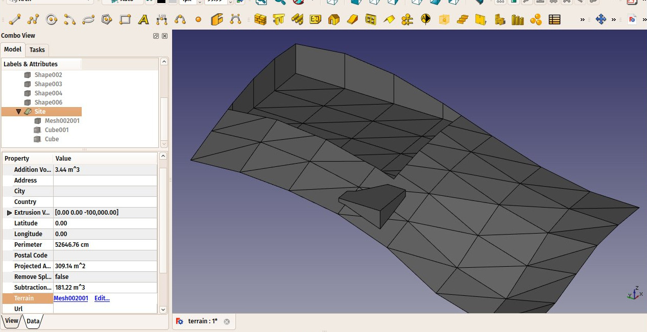
La geometría del sitio se volverá a calcular y se volverán a calcular las áreas, el perímetro y las propiedades de volúmenes.
Diagramas solares y eólicos
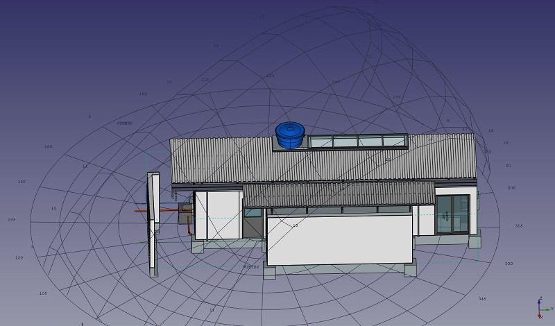
Si Ladybug está instalado en su sistema, Arch Sites puede mostrar un diagrama solar y/o una rosa de los vientos. Para ello, DatosLongitud, DatosLatitud y DatosDeclinación (antes DatosDesviación Norte) deben estar correctamente configurados, y VistaDiagrama Solar o VistaRosa de Viento configurados a true. Respectivamente introducido en la versión 0.17 y introducido en la versión 0.19
Notes
- The diagram can be scaled, oriented and centered on a specific point in the model. It can also be turned on and off. At this point it is a visual rather than functional feature, and provided for display purposes only.
- If you don't have Ladybug, pysolar (version 0.7 and above) is still supported to generate sun path diagrams, but not wind roses. However, Ladybug is a much more powerful tool that will probably be used more in the future, so we recommend using it instead of pysolar. Ladybug can be installed simply via the pip Python package manager.
Scripting
Guión
Ver también: Borrador API y Fundamentos de Guión FreeCAD.
La herramienta Ubicación se puede utilizar en macros y desde la consola de Python utilizando la siguiente función:
Site = makeSite(objectslist=None, baseobj=None, name="Site")
- Crea un objeto
Sitea partir deobjectslist, que es una lista de objetos, obaseobj, que es unShapeoTerrain.
Ejemplo:
import FreeCAD, Draft, Arch

p1 = FreeCAD.Vector(0, 0, 0)
p2 = FreeCAD.Vector(2000, 0, 0)
baseline = Draft.makeLine(p1, p2)
Wall = Arch.makeWall(baseline, length=None, width=150, height=2000)
FreeCAD.ActiveDocument.recompute()

Building = Arch.makeBuilding([Wall])
Site = Arch.makeSite([Building])

FreeCAD.ActiveDocument.recompute()
FreeCAD.Gui.ActiveDocument.ActiveView.viewIsometric()
Diagrama solar
Siempre que el módulo pysolar esté presente, se puede añadir un diagrama solar al sitio. Establezca los ángulos de longitud, latitud y declinación según corresponda, así como una escala adecuada para el tamaño de su modelo.
At this time, the diagram serves only informative purposes and is there for visual display. For a sun path diagram that enables visualizing shadows and interactively changing dates and times, the best option is to use an external website that allows uploading 3D models. Some of them support .obj and .stl formats for instance, which can be exported to with FreeCAD.
Tenga en cuenta que se requiere Pysolar 0.7 o superior, y esta versión sólo funciona con Python 3.
Site.Longitude = -46.38
Site.Latitude = -23.33
Site.Declination = 30
# Uncomment if you want to show the compass
# Site.ViewObject.Compass = True

Site.ViewObject.SolarDiagram = True
Site.ViewObject.SolarDiagramScale = 10000
FreeCAD.ActiveDocument.recompute()
Diagrama solar independiente del ubicación
Se puede crear un diagrama solar con la siguiente función, independientemente de cualquier sitio.
Node = makeSolarDiagram(longitude, latitude, scale=1, complete=False)
- Crea un diagrama solar como un nodo Pivy, utilizando
longitudeylatitude, con unscaleopcional. - Si
completeesTrue, se dibujan los 12 meses, que muestran el analemma solar completo.
import FreeCADGui, Arch

Node = Arch.makeSolarDiagram(-46.38, -23.33, scale=10000, complete=True)
FreeCAD.Gui.ActiveDocument.ActiveView.getSceneGraph().addChild(Node)
- 2D drafting: Sketch, Line, Polyline, Circle, Arc, Arc by 3 points, Fillet, Ellipse, Polygon, Rectangle, B-spline, Bézier curve, Cubic Bézier curve, Point
- 3D/BIM: Project, Site, Building, Level, Space, Wall, Curtain Wall, Column, Beam, Slab, Door, Window, Pipe, Pipe Connector, Stairs, Roof, Panel, Frame, Fence, Truss, Equipment
- Reinforcement tools: Custom Rebar, Straight Rebar, U-Shape Rebar, L-Shape Rebar, Stirrup, Bent-Shape Rebar, Helical Rebar, Column Reinforcement, Beam Reinforcement, Slab Reinforcement, Footing Reinforcement
- Generic 3D tools: Profile, Box, Shape builder..., Facebinder, Objects library, Component, External reference
- Annotation: Text, Shape from text, Aligned dimension, Horizontal dimension, Vertical dimension, Leader, Label, Axis, Axes System, Grid, Section Plane, Hatch, Page, View, Shape-based view
- Snapping: Snap lock, Snap endpoint, Snap midpoint, Snap center, Snap angle, Snap intersection, Snap perpendicular, Snap extension, Snap parallel, Snap special, Snap near, Snap ortho, Snap grid, Snap working plane, Snap dimensions, Toggle grid, Working Plane Top, Working Plane Front, Working Plane Side
- Modify: Move, Copy, Rotate, Clone, Create simple copy, Make compound, Offset, 2D Offset..., Trimex, Join, Split, Scale, Stretch, Draft to sketch, Upgrade, Downgrade, Add component, Remove component, Array, Path array, Polar array, Point array, Cut with plane, Mirror, Extrude..., Difference, Union, Intersection
- Manage: BIM Setup..., Views manager, Manage project..., Manage doors and windows..., Manage IFC elements..., Manage IFC quantities..., Manage IFC properties..., Manage classification..., Manage layers..., Material, Schedule, Preflight checks..., Annotation styles...
- Utils: Toggle bottom panels, Move to Trash, Working Plane View, Select group, Set slope, Create working plane proxy, Add to construction group, Split Mesh, Mesh to Shape, Select non-manifold meshes, Remove Shape from Arch, Close Holes, Merge Walls, Check, Toggle IFC Brep flag, Toggle subcomponents, Survey, IFC Diff, IFC explorer, Create IFC spreadsheet..., Image plane, Unclone, Rewire, Glue, Reextrude
- Panel tools: Panel, Panel Cut, Panel Sheet, Nest
- Structure tools: Structure, Structural System, Multiple Structures
- IFC tools: IFC Diff..., IFC Expand, Make IFC project, IfcOpenShell update
- Nudge: Nudge Switch, Nudge Up, Nudge Down, Nudge Left, Nudge Right, Nudge Rotate Left, Nudge Rotate Right, Nudge Extend, Nudge Shrink
- Additional: Preferences, Fine tuning, Import Export Preferences, IFC, DAE, OBJ, JSON, 3DS, SHP
- Getting started
- Installation: Download, Windows, Linux, Mac, Additional components, Docker, AppImage, Ubuntu Snap
- Basics: About FreeCAD, Interface, Mouse navigation, Selection methods, Object name, Preferences, Workbenches, Document structure, Properties, Help FreeCAD, Donate
- Help: Tutorials, Video tutorials
- Workbenches: Std Base, Assembly, BIM, CAM, Draft, FEM, Inspection, Material, Mesh, OpenSCAD, Part, PartDesign, Points, Reverse Engineering, Robot, Sketcher, Spreadsheet, Surface, TechDraw, Test Framework
- Hubs: User hub, Power users hub, Developer hub


