Arch Window/es
|
|
| Ubicación en el Menú |
|---|
| Arquitectura → Ventana |
| Entornos de trabajo |
| Arquitectura |
| Atajo de teclado por defecto |
| W I |
| Introducido en versión |
| - |
| Ver también |
| Arquitectura Muro, Arquitectura Añadir |
Descripción
Un Arquitectura Ventana es un objeto base para todo tipo de objetos "incrustables", como ventanas y puertas. Está diseñado para ser independiente, o "alojado" dentro de otro componente como un Arquitectura Muro, Arquitectura Estructura, o Arquitectura Techo. Tiene su propia geometría, que puede estar formada por varios componentes sólidos (comúnmente un marco y paneles interiores), y también define un volumen que se sustrae de los objetos anfitriones, para crear una abertura.
Los objetos ventana se basan en objetos 2D cerrados, como Borrador Rectángulos o Croquis, que se utilizan para definir sus componentes internos. Por lo tanto, el objeto 2D base debe contener varios hilos cerrados, que pueden combinarse para formar paneles rellenos (un hilo) o marcos (varios hilos).
La herramienta Ventana presenta varios preajustes'; esto permite al usuario crear tipos comunes de ventanas y puertas con ciertos parámetros editables, sin necesidad de que el usuario cree manualmente los objetos y componentes 2D base.
All information applicable to an Arch Window also applies to an Arch Door, as it's the same underlying object.
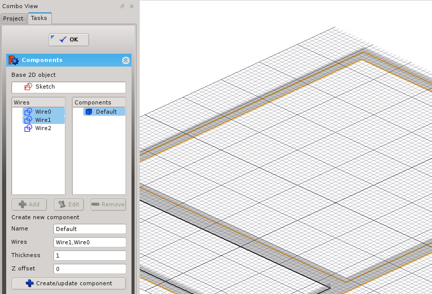
Complex window being constructed on top of a Sketch. When entering the window's edit mode you can create different components, set their thickness, and select and assign wires from the sketch to them.
Utilización
Usando un preajustado
- Opcionalmente, seleccione un objeto Arch. Si no se selecciona ningún objeto, la ventana se insertará en el objeto debajo del mouse al colocar la ventana.
- Presione el botón
 Arch Window, o presione W luego la tecla I
 - Seleccione uno de los predefinidos en la lista
- Completa los parámetros deseados
- Presione el botón Ok
Additional presets
In addition to the default presets, the window tool can also use custom presets. A custom preset is a FreeCAD file containing a single window based on a parametric sketch that has two named constrains: Width and Height. Custom presets can be placed in the following locations:
The window tool will always search this pair of locations:
$ROOT_DIR/Arch/Doors/Custom/
$ROOT_DIR/Arch/Windows/Custom/
If you install the Parts Library from the Addon Manager, the window tool will also search this library for additional presets at this pair of locations:
$ROOT_DIR/Mod/parts_library/Architectural Parts/Doors/Custom/
$ROOT_DIR/Mod/parts_library/Architectural Parts/Windows/Custom/
- The $ROOT_DIR is the user directory where FreeCAD configuration files, macros, and external workbenches are stored. It can be found be entering
FreeCAD.getUserAppDataDir()in the Python Console.- On Linux it is usually /home/username/.local/share/FreeCAD/
- On Windows it is usually C:\Users\username\Application Data\FreeCAD\
- On Mac OSX it is usually /Users/username/Library/Preferences/FreeCAD/
- The subdirectory name Custom is just a suggestion, any name can be used. But the files must be placed in one or more subdirectories inside the Doors or Windows directories.
Custom presets will be available in the window tool's presets dropdown menu. Presets in library locations will also be available in the Parts Library dialog.
Creando desde cero
- Opcionalmente, seleccione una cara en el objeto Arch donde desee que se incluya la ventana
- Cambie al Sketcher Workbench
- Crea un nuevo boceto
- Dibuja uno o más lineas cerradas
- Cerrar el boceto
- Vuelva al Arch Workbench
- Presione el botón
 Arch Window, o presione W luego la tecla I
 - Ingrese al modo Editar haciendo doble clic en la ventana en la vista de árbol, para ajustar los componentes de la ventana
Predefinidos
Los siguientes predefinidos están disponibles:
-
Fixed
-
Open 1-pane
-
Open 2-pane
-
Sash 2-pane
-
Sliding 2-pane
-
Simple door
-
Glass door
-
Sliding 4-pane
-
Awning
-
Opening only introduced in 1.0
Componentes constructivos
Windows puede incluir 3 tipos de componentes: paneles, marcos y louvres. Los paneles y las louvres están hechos de una linea cerrada, que se extruye, mientras que los marcos están hechos de 2 o más lineas cerradas, donde cada uno se extruye, luego los más pequeños se restan del más grande. Puede acceder, crear, modificar y eliminar componentes de una ventana en el modo de edición (haga doble clic en la ventana en la vista de árbol). Los componentes tienen las siguientes propiedades:
- Nombre: un nombre para el componente
- Tipo: el tipo de componente. Puede ser "Marco", "Panel de vidrio", "Panel sólido" o "Louvres"
- Wires: una lista de lineas separadas por comas en la que el componente se basa
- Grosor: el espesor de extrusión del componente
- Z Offset: la distancia entre el componente y su base 2D linea(s)
- Bisagra: Esto le permite seleccionar un borde del objeto base 2D, luego establecer ese borde como una bisagra para este componente y los siguientes en la lista
- Modo de apertura: si definió una bisagra en este componente o en cualquier otro anterior de la lista, establecer el modo de apertura permitirá que la ventana parezca abierta o que muestren símbolos de apertura 2D en planta o alzado.
Opciones
- Windows comparte las propiedades y comportamientos comunes de todos Arch Components
- Si la casilla Autoincluir en el panel de tareas de creación de ventanas está desmarcada, la ventana no se insertará en ningún objeto Anfitrion al momento de la creación.
- Agregue una ventana seleccionada a Muro seleccionando ambos, luego presione el botón
 Arch Add.
 - Eliminar una ventana seleccionada de un muro seleccionando la ventana, luego presionando el botón
 Arch Remove.
 - Cuando se usan predefinidos, a menudo es conveniente activar el "Near" Draft Snap, para que pueda ajustar su ventana a una cara existente.
- El agujero creado por una ventana en su objeto anfitrión está determinado por dos propiedades: Profundidad del agujero y Hole Wire (introduced in 0.17). El número de Hole Wire se puede seleccionar en la vista 3D desde el panel de tareas de la ventana disponible al hacer doble clic en la ventana en la vista de árbol
- Windows puede hacer uso de Multi-Materiales. La ventana buscará en el Multi-Material adjunto capas de material con el mismo nombre para cada uno de sus componentes de ventana, y lo usará si encuentra alguno. Por ejemplo, un componente llamado "OuterFrame" buscará en el Multi-Material adjunto, para una capa de material llamada "OuterFrame". Si se encuentra dicha capa de material, su material se atribuirá al componente OuterFrame. El valor de espesor de la capa de material no se tiene en cuenta.
Aberturas
See also: Tutorial for open windows
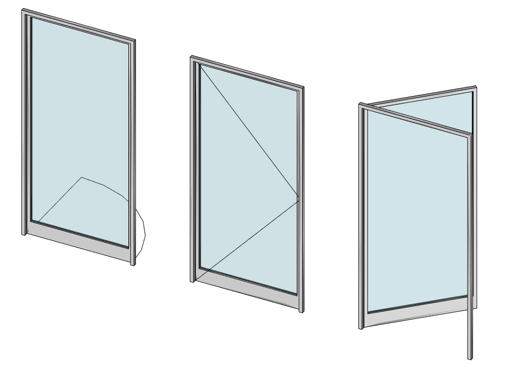
Las puertas y ventanas pueden aparecer parcial o totalmente abiertas en el modelo 3D, o pueden mostrar símbolos de apertura tanto en plano como en elevación. En consecuencia, estos también aparecerán en las vistas 2D extraídas generadas por Draft Shape2DView/es o TechDraw Workbench/es o Drawing Workbench/es. Para obtener esto, al menos uno de los componentes de la ventana debe tener una bisagra y un modo de apertura definido (consulte la sección "Componentes de la construcción" más arriba). Luego, usando las propiedades Apertura, Plan de símbolos o Elevación de símbolos, puede configurar el aspecto de la ventana:
Defining window types
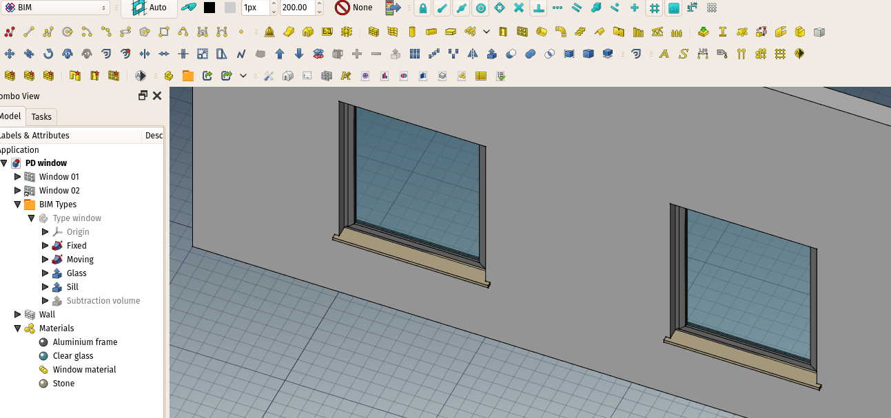
Windows can also take advantage of other tools, specifically PartDesign workflows, to define a type. A type is an object that defines the shape of the window. This is specially well suited to work with App Parts:
Download the example file shown above
Example workflow
- Create a window frame object, a glass panel, and any other window component you need, using Part Workbench or PartDesign tools.
- For example, create a base rectangular sketch for your window, then a profile sketch for the frame, and create a Part Sweep to sweep the profile around the base sketch. Create a Part Offset2D from the base sketch, then a Part Extrude to create the glass panel
- Make sure all these pieces have a unique, meaningful name (for example, "Frame" or "Glass panel")
- Create an App Part, and place all your subcomponents in it
- Create a volume to be subtracted from the wall, for example by extruding the base sketch. Add this volume to the App Part. Make sure the volume is turned off
- You can add 3 properties to your App Part, by right-clicking its Property View and selecting "Add Property". Add the following properties (all of them are optional, the group doesn't matter):
- Height as a PropertyLength and link it, for example, to a vertical constraint of your base sketch
- Width as a PropertyLength and link it, for example, to a horizontal constraint of your base sketch
- Subvolume as a PropertyLink and link it to the volume to be subtracted that we created above
- Tag as a PropertyString
Our window type is now ready. We can create window objects from it, simply by selecting the App Part and pressing the window button. The "Height", "Width", "Subvolume" and "Tag" properties of the window will be linked to the corresponding property of the App Part, if existing.
Materials
To build a material for type-based windows:
- Create a multi-material
- Create one entry in the multi-material for each component of your App Part. For example, one "Frame", one "Glass panel" as we used above. Make sure to use the exact same name.
- Attribute that multi-material to each of the windows derived from the same type
You can use any other kind of workflow than the one described above, the important points to remember are:
- The type object must be one object, no matter the type (App Part, PartDesign Body, Part Compound, or even another Arch Window)
- The type object must have a "Subvolume" property (linked to the window's Subvolume property) for openings in host objects to work
- The type object must have a "Group" property with different children with same names as multi-material items for multi-materials to work
Propiedades
An Arch Window object shares the common properties and behaviors of all Arch Components.
Data
Window
- DATOS Height: El alto de esta ventana
- DATOS Width: El ancho de esta ventana
- DATOS Hole Depth: La profundidad del agujero creado por esta ventana en su objeto anfitrión
- DATOS Hole Wire: el número de linea del objeto base que se usa para crear un agujero en el objeto anfitrión de esta ventana. Este valor puede establecerse gráficamente al hacer doble clic en la ventana en la vista de árbol. Establecer un valor de 0 hará que la ventana seleccione automáticamente su linea más grande para el agujero.
- DATOS Window Parts: una lista de cadenas (5 cadenas por componente, configurando las opciones de componentes anteriores)
- DATOS Louvre Width: si alguno de los componentes está configurado en "Louvres", esta propiedad define el tamaño de los elementos del louvre
- DATOS Louvre Spacing: si alguno de los componentes está configurado en "Louvres", esta propiedad define el espacio entre los elementos del Louvre
- DATOS Opening: todos los componentes que tienen su modo de apertura establecido, y siempre que se haya definido una bisagra en ellos o en un componente anterior de la lista, aparecerán abiertos en un porcentaje definido por este valor
- DATOS Symbol Plan: muestra el símbolo de apertura 2D en el plan
- DATOS Elevación de símbolo: muestra el símbolo de apertura 2D en alzado
Scripting
Programación
La herramienta Ventana puede usarse en macros y desde la consola de Python utilizando la siguiente función:
Window = makeWindow(baseobj=None, width=None, height=None, parts=None, name="Window")
- crea una ventana basada en el objeto dado
Ejemplo:
import FreeCAD, Draft, Arch

Rect1 = Draft.makeRectangle(length=900, height=3000)
Window = Arch.makeWindow(Rect1)
FreeCAD.ActiveDocument.recompute()
You can also create a Window from a preset.
Window = makeWindowPreset(windowtype, width, height, h1, h2, h3, w1, w2, o1, o2, placement=None)
Ejemplo:
import FreeCAD, Arch

base = FreeCAD.Vector(2000, 0, 0)
Axis = FreeCAD.Vector(1, 0, 0)
place=FreeCAD.Placement(base, FreeCAD.Rotation(Axis, 90))

Door = Arch.makeWindowPreset("Simple door",
                             width=900, height=2000,
                             h1=100, h2=100, h3=100, w1=200, w2=100, o1=0, o2=100,
                             placement=place)
- 2D drafting: Sketch, Line, Polyline, Circle, Arc, Arc by 3 points, Fillet, Ellipse, Polygon, Rectangle, B-spline, Bézier curve, Cubic Bézier curve, Point
- 3D/BIM: Project, Site, Building, Level, Space, Wall, Curtain Wall, Column, Beam, Slab, Door, Window, Pipe, Pipe Connector, Stairs, Roof, Panel, Frame, Fence, Truss, Equipment
- Reinforcement tools: Custom Rebar, Straight Rebar, U-Shape Rebar, L-Shape Rebar, Stirrup, Bent-Shape Rebar, Helical Rebar, Column Reinforcement, Beam Reinforcement, Slab Reinforcement, Footing Reinforcement
- Generic 3D tools: Profile, Box, Shape builder..., Facebinder, Objects library, Component, External reference
- Annotation: Text, Shape from text, Aligned dimension, Horizontal dimension, Vertical dimension, Leader, Label, Axis, Axes System, Grid, Section Plane, Hatch, Page, View, Shape-based view
- Snapping: Snap lock, Snap endpoint, Snap midpoint, Snap center, Snap angle, Snap intersection, Snap perpendicular, Snap extension, Snap parallel, Snap special, Snap near, Snap ortho, Snap grid, Snap working plane, Snap dimensions, Toggle grid, Working Plane Top, Working Plane Front, Working Plane Side
- Modify: Move, Copy, Rotate, Clone, Create simple copy, Make compound, Offset, 2D Offset..., Trimex, Join, Split, Scale, Stretch, Draft to sketch, Upgrade, Downgrade, Add component, Remove component, Array, Path array, Polar array, Point array, Cut with plane, Mirror, Extrude..., Difference, Union, Intersection
- Manage: BIM Setup..., Views manager, Manage project..., Manage doors and windows..., Manage IFC elements..., Manage IFC quantities..., Manage IFC properties..., Manage classification..., Manage layers..., Material, Schedule, Preflight checks..., Annotation styles...
- Utils: Toggle bottom panels, Move to Trash, Working Plane View, Select group, Set slope, Create working plane proxy, Add to construction group, Split Mesh, Mesh to Shape, Select non-manifold meshes, Remove Shape from Arch, Close Holes, Merge Walls, Check, Toggle IFC Brep flag, Toggle subcomponents, Survey, IFC Diff, IFC explorer, Create IFC spreadsheet..., Image plane, Unclone, Rewire, Glue, Reextrude
- Panel tools: Panel, Panel Cut, Panel Sheet, Nest
- Structure tools: Structure, Structural System, Multiple Structures
- IFC tools: IFC Diff..., IFC Expand, Make IFC project, IfcOpenShell update
- Nudge: Nudge Switch, Nudge Up, Nudge Down, Nudge Left, Nudge Right, Nudge Rotate Left, Nudge Rotate Right, Nudge Extend, Nudge Shrink
- Additional: Preferences, Fine tuning, Import Export Preferences, IFC, DAE, OBJ, JSON, 3DS, SHP
- Getting started
- Installation: Download, Windows, Linux, Mac, Additional components, Docker, AppImage, Ubuntu Snap
- Basics: About FreeCAD, Interface, Mouse navigation, Selection methods, Object name, Preferences, Workbenches, Document structure, Properties, Help FreeCAD, Donate
- Help: Tutorials, Video tutorials
- Workbenches: Std Base, Assembly, BIM, CAM, Draft, FEM, Inspection, Material, Mesh, OpenSCAD, Part, PartDesign, Points, Reverse Engineering, Robot, Sketcher, Spreadsheet, Surface, TechDraw, Test Framework
- Hubs: User hub, Power users hub, Developer hub


