Manual:BIM modeling/ro
- Introducere
- Descoperind FreeCAD
- Lucrul cu FreeCAD
- Programarea prin script Python
- Comunitatea
BIM înseamnă Building Information Modeling. Definiția exactă a ceea ce este variază, dar putem spune pur și simplu că în prezent sunt modelate clădiri și alte structuri mari, cum ar fi poduri, tuneluri etc. Modelele BIM se bazează, de obicei, pe modele 3D și includ, de asemenea, o serie de informații suplimentare, cum ar fi informații despre materiale, relații cu alte obiecte sau modele sau instrucțiuni speciale pentru construirea sau întreținerea. Această informație suplimentară permite toate tipurile de analize avansate ale modelului, cum ar fi rezistența structurală, costurile și estimările timpului de construcție sau calculele consumului de energie.
Atelierul Arch(Arhitectură) Arch Workbench a FreeCAD implementează o serie de instrumente și facilități pentru modelarea BIM. Deși are un scop diferit, este făcut să lucreze în strânsă integrare cu restul FreeCAD: Orice realizat cu orice alt atelier de lucru al FreeCAD poate deveni un obiect Arch sau poate fi folosit ca bază pentru un obiect Arch.
Ca și în Atelierul PartDesign Workbench, obeictele produse În Arch Workbench sunt concepute pentru a fi construite în lumea reală. Prin urmare, ele trebuie să fie solide . Instrumentele atelierului Arch au, de obicei, grijă de aceasta în mod automat și oferă, de asemenea, unelte utilitare pentru a vă ajuta să verificați validitatea obiectelor.
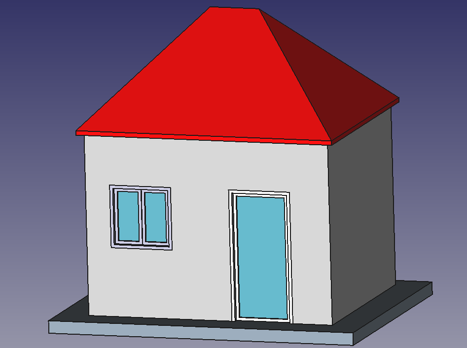
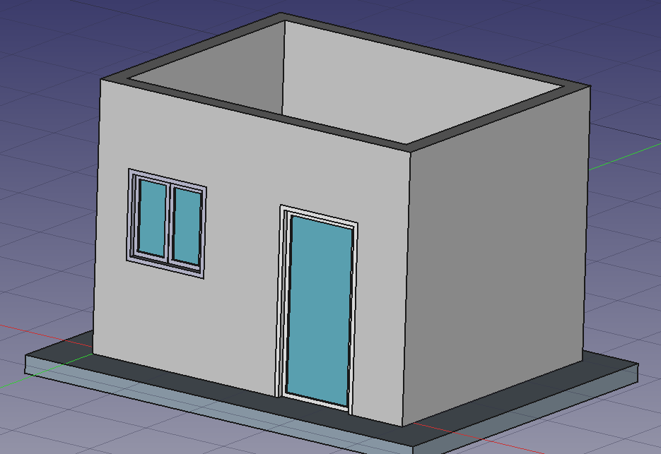
În acest capitol vom vedea cum să modelam această clădire mică:
- Creați un nou document și comutați la Arch Workbench.
- Deschideți meniulEdit -> Preferences -> Draft -> Grid and Snapping and set the grid spacing setați la 1000 mm, așa că avem o rețea/grilă cu nitatea de un metru, care va fi convenabilă pentru dimensiunea clădirii noastre.
- În snapping toolbar, asigurați-vă că butonul
 grid snap este activat , astfel ca noi să putem utiliza grila cât mai mult posibil.
 - Definiți planul ca fiind XY Working Plane
- Desenați patru linii cu instrumentul
 Draft Line Puteți introduce coordonatele manual sau pur și simplu alegeți punctele de pe grilă cu mouse-ul:
- From point (0,0) to point (0,3)
- From point (0,3) to point (4,3)
- From point (4,3) to point (4,0)
- From point (4,0) to point (0,0)
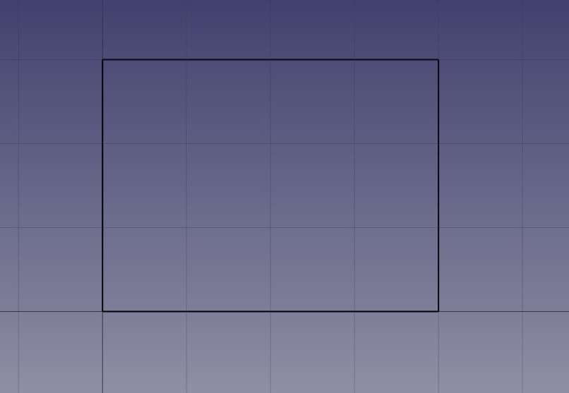
Observați că am tras mereu în aceeași direcție (în sensul acelor de ceasornic). Acest lucru nu este necesar, dar se va asigura că pereții pe care îi vom construi în continuare au toți aceleași direcții stânga și dreapta. S-ar putea să credeți că am putea pur și simplu să trasăm un dreptunghi aici, ceea ce este adevărat. Dar cele patru linii ne vor permite să ilustrăm mai bine cum să adăugăm un obiect în altul.
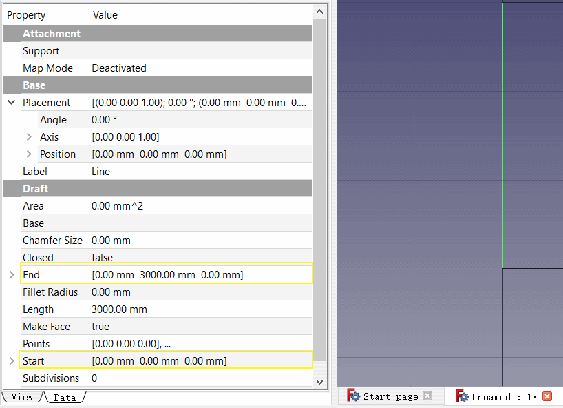
- Once you have created the lines check their start and end points and adjust if necessary to get them exactly correct.
- Selectați prima linie, apoi apăsați butonul
 Wall .
 - Repetați pentru celelalte linii, până aveți 4 pereți.
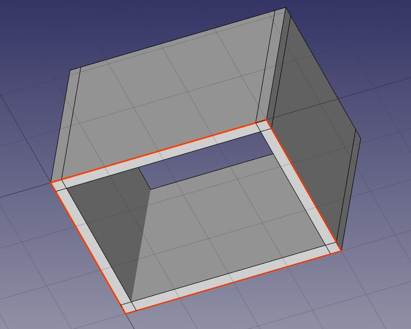
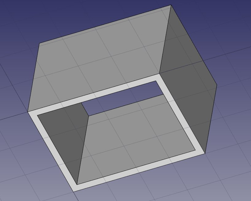
- Selectați cei patru pereți, și definiți: Height property to 3.00m and their Alignment property to left. Dacă nu ați tras liniile în aceeași ordine ca și cele de mai sus, unii dintre pereți ar putea fi orientați spre stânga și spre dreapta și ar fi trebuit să fie setați la dreapta. Veți obține patru pereți intersectați, în interiorul liniilor de bază:
Acum trebuie să ne alăturăm acestor pereți împreună, astfel încât să se intersecteze în mod corespunzător. Acest lucru nu este necesar atunci când pereții dvs. sunt desenați într-un mod în care se conectează deja cu ușurință, aici avem nevoie, deoarece se intersectează. În Arh, acest lucru se face prin alegerea unuia dintre pereți drept "host" și adăugarea celorlalte ca "additions". Toate obiectele Arch pot avea orice număr de adăugiri (obiectelor ale căror geometrie va fi adăugate la geometria gazdei) și subtracțiile (obiecte a căror geometrie va fi scăzută). Adăugările și scăderea unui obiect pot fi gestionate oricând prin dublu clic pe obiectul din arborescență.
- Selectați cei patru pereți cu tasta Ctrl apăsată, ultimul fiind zidul pe care l-ați ales sădevină 'host'
- Apăsați butonul
 Add. Cei patru pereții sunt acum transformați într-unul singur:
The individual walls are however still accessible, by expanding the wall in the tree view.
- Let's now place a door. In FreeCAD, doors are considered a special case of windows, so this is done using the Window tool.
- Start by selecting the wall. This is not necessary, but a good habit to take. If an object is selected when starting the window tool, you will force the window to be inserted in that object, even if you snap to another object.
- Set the Working Plane to auto so we are not restricted to the ground plane
- Press the
 Window button.
 - In the window creation panel, select the Simple door preset, and set its Width to 0.9m and its Height to 2.1m
- Make sure the
 Near snap location is turned on, so we can snap on faces
 - Place your window roughly on the middle of the front face of the wall:
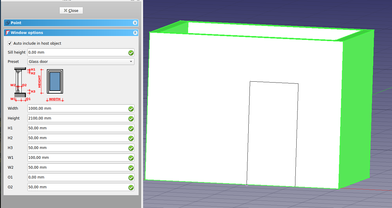
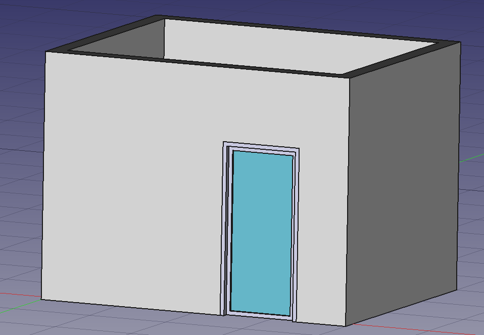
- După ce faceți clic, fereastra noastră este pe fațeta corectă, dar nu exact unde vrem:
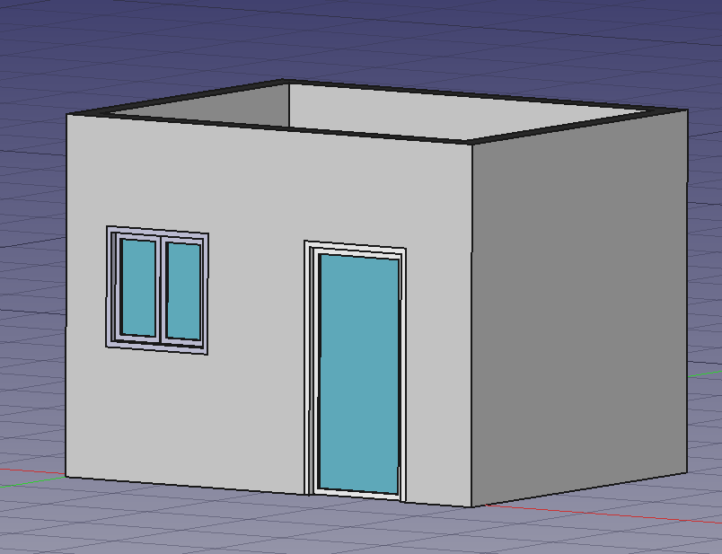
- Repeat the operation to place a window: Select the wall, press the window tool, select the Open 2-pane preset, and place a 1m x 1m window in the same face as the door. Set the placement of the underlying sketch to position x = 0.6m, y = 0, z = 1.1m, so the upper line of the window is aligned to the top of the door.
Windows are always built on sketches. It is easy to create custom windows by first creating a sketch on a face, then turning it into a window by selecting it, then pressing the window button. Then, the window creation parameters, that is, which wires of the sketch must be extruded and how much, can be defined by double-clicking the window in the tree view. Now, let's create a slab:
- Set the Working Plane to XY plane
- Create a
 rectangle with a length of 5m, a height of 4m, and place it at position x:-0.5m, y:-0.5m, z:0.
 - Select the rectangle
- Click the
 structure tool to create a slab from the rectangle
 - Set the height property of the slab to 0.2m and its normal direction to (0,0,-1) because we want it to extrude downwards. We could also simply have moved it 0.2m down, but it is always good practice to keep extruded objects at the same place as their base profile.
- Set the Role property of the slab to slab. This is not necessary in FreeCAD, but is important for IFC export, as it will ensure that the object is exported with the correct IFC type.
- We can now easily build a simple slab on top of them, by drawing a rectangle directly on the top plane of the beams. Select a top face of one of the beams
- Press the
 working plane button. The working plane is now set to that face.
 - Create a rectangle, snapping to two opposite points of the border beams:
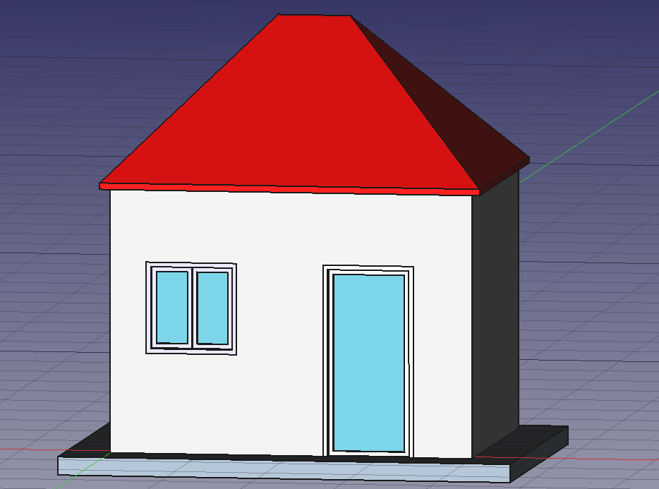
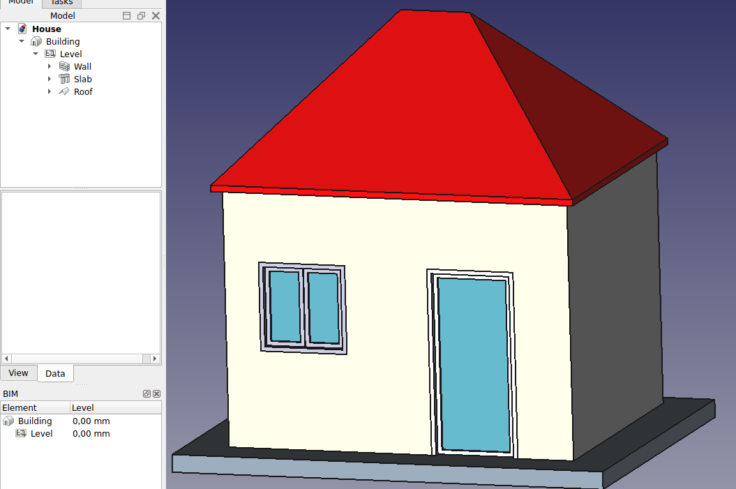
That's it, our model is now complete. We should now organize it so it exports correctly to IFC. The IFC format requires that all objects of a building are inside a building object, and optionally, inside a story. It also requires that all buildings are placed on a site, but the IFC exporter of FreeCAD will add a default site automatically if needed, so we don't need to add one here.
Our model is now ready to export:
The IFC format is one of the most precious assets in a free BIM world, because it allows the exchange of data between any application and actor of the construction world, in an open manner (the format is open, free and maintained by an independent consortium). Exporting your BIM models as IFC ensures that anyone can see and analyze them, no matter the application used.
- Select the top object you want to export, that is, the Building object.
- Select menu File -> Export -> Industry Foundation Classes and save your file.
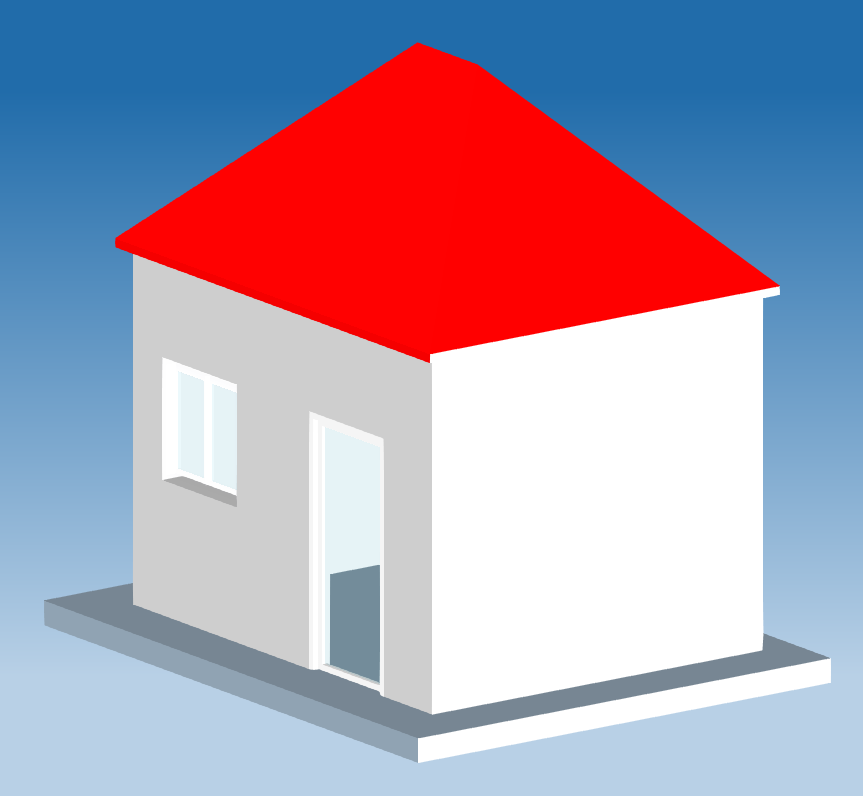
- The resulting IFC file can now be opened in a wide range of applications and viewers (the image below shows the file opened in the free IfcPlusPlus viewer). Checking the exported file in such a viewer application before distributing it to other people is important to check that all the data contained in the file is correct. FreeCAD itself can also be used to re-open the resulting IFC file.
We will now place some dimensions. Unlike the previous chapter, where we drew all the dimensions directly on the Drawing sheet, we will use another method here, and place Draft dimensions directly in the 3D model. These dimensions will then be placed on the Drawing sheet automatically. We will first make two groups for our dimensions, one for the dimensions that will appear in the plan view, and another for those that appear on the elevation.

Our page is now ready, and we can export it to SVG or DXF formats, or print it. The SVG format allows you to open the file using illustration applications such as Inkscape, with which you can quickly enhance technical drawings and turn them into much nicer presentation drawings. It offers many more possibilities than the DXF format.
Downloads
- The file produced during this exercise: https://github.com/yorikvanhavre/FreeCAD-manual/blob/master/files/house.FCStd
- The IFC file exported from the above file: https://github.com/yorikvanhavre/FreeCAD-manual/blob/master/files/house.ifc
- The SVG file exported from the above file: https://github.com/yorikvanhavre/FreeCAD-manual/blob/master/files/house.svg
De citit în plus
- 2D drafting: Sketch, Line, Polyline, Circle, Arc, Arc by 3 points, Fillet, Ellipse, Polygon, Rectangle, B-spline, Bézier curve, Cubic Bézier curve, Point
- 3D/BIM: Project, Site, Building, Level, Space, Wall, Curtain Wall, Column, Beam, Slab, Door, Window, Pipe, Pipe Connector, Stairs, Roof, Panel, Frame, Fence, Truss, Equipment
- Reinforcement tools: Custom Rebar, Straight Rebar, U-Shape Rebar, L-Shape Rebar, Stirrup, Bent-Shape Rebar, Helical Rebar, Column Reinforcement, Beam Reinforcement, Slab Reinforcement, Footing Reinforcement
- Generic 3D tools: Profile, Box, Shape builder..., Facebinder, Objects library, Component, External reference
- Annotation: Text, Shape from text, Aligned dimension, Horizontal dimension, Vertical dimension, Leader, Label, Axis, Axes System, Grid, Section Plane, Hatch, Page, View, Shape-based view
- Snapping: Snap lock, Snap endpoint, Snap midpoint, Snap center, Snap angle, Snap intersection, Snap perpendicular, Snap extension, Snap parallel, Snap special, Snap near, Snap ortho, Snap grid, Snap working plane, Snap dimensions, Toggle grid, Working Plane Top, Working Plane Front, Working Plane Side
- Modify: Move, Copy, Rotate, Clone, Create simple copy, Make compound, Offset, 2D Offset..., Trimex, Join, Split, Scale, Stretch, Draft to sketch, Upgrade, Downgrade, Add component, Remove component, Array, Path array, Polar array, Point array, Cut with plane, Mirror, Extrude..., Difference, Union, Intersection
- Manage: BIM Setup..., Views manager, Manage project..., Manage doors and windows..., Manage IFC elements..., Manage IFC quantities..., Manage IFC properties..., Manage classification..., Manage layers..., Material, Schedule, Preflight checks..., Annotation styles...
- Utils: Toggle bottom panels, Move to Trash, Working Plane View, Select group, Set slope, Create working plane proxy, Add to construction group, Split Mesh, Mesh to Shape, Select non-manifold meshes, Remove Shape from Arch, Close Holes, Merge Walls, Check, Toggle IFC Brep flag, Toggle subcomponents, Survey, IFC Diff, IFC explorer, Create IFC spreadsheet..., Image plane, Unclone, Rewire, Glue, Reextrude
- Panel tools: Panel, Panel Cut, Panel Sheet, Nest
- Structure tools: Structure, Structural System, Multiple Structures
- IFC tools: IFC Diff..., IFC Expand, Make IFC project, IfcOpenShell update
- Nudge: Nudge Switch, Nudge Up, Nudge Down, Nudge Left, Nudge Right, Nudge Rotate Left, Nudge Rotate Right, Nudge Extend, Nudge Shrink
- Additional: Preferences, Fine tuning, Import Export Preferences, IFC, DAE, OBJ, JSON, 3DS, SHP