Manual:BIM modeling
- Introduction
- Discovering FreeCAD
- Working with FreeCAD
- Python scripting
- The community
Building Information Modeling is a process used in architecture, engineering, and construction to create and manage digital representations of physical structures. It integrates not only 3D geometry but also critical data such as materials, costs, and schedules, allowing for advanced analysis and collaboration throughout the entire lifecycle of a project.
In FreeCAD, BIM functionality has evolved significantly, especially with the release of version 1.0, where the previously separate Arch and BIM workbenches were merged into an integrated BIM Workbench. This consolidation streamlines workflows, allowing users to model, document, and manage building projects more efficiently within a single environment.
A major advancement introduced in FreeCAD v1.0 is the adoption of the Native IFC concept. Previously, like most BIM applications, FreeCAD translated data back and forth between its internal data model and the IFC (Industry Foundation Classes) file format, leading to potential data loss during the opening and saving processes. With Native IFC, FreeCAD users can now open, manipulate, and save IFC files directly, where the IFC file itself serves as the data structure. This approach eliminates unnecessary data translation and ensures that modifications are saved without rewriting the entire file, making it compatible with version control systems like Git and providing a more transparent, precise workflow for handling IFC files.
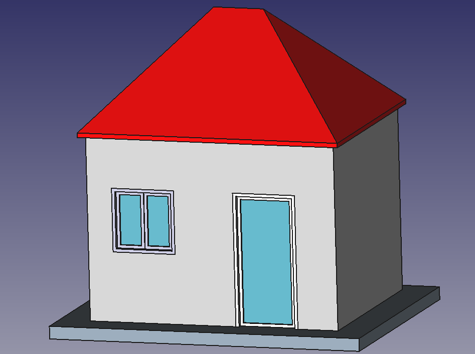
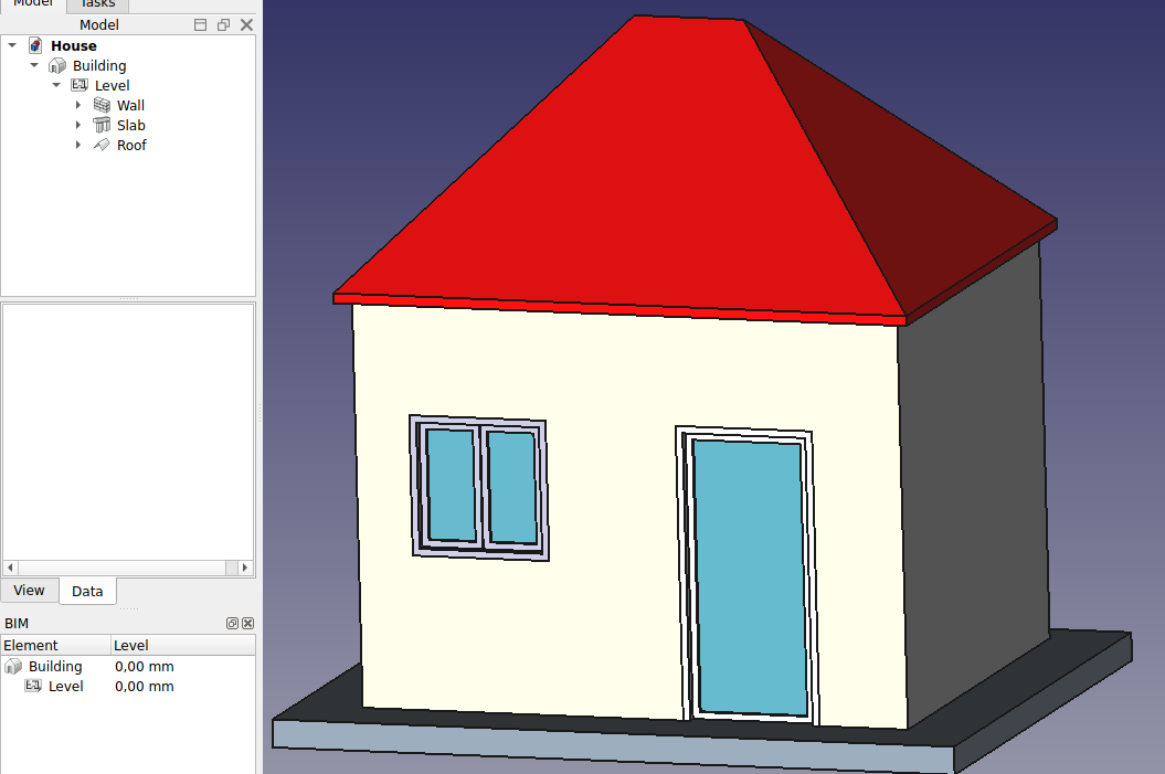
In this chapter, we will see how to model this small building:
- Create a new document, and switch to the
 BIM Workbench.
 - Open menu Edit → Preferences → Draft → Grid and Snapping and set:
- Main lines every
10. - Grid spacing
1000mmto have a one meter-based grid, which is convenient for the size of our building. - Grid size
100 lines.
- Main lines every
- On the snapping toolbar make sure the
 Snap grid button is enabled, so we can use the grid as much as possible.
 - If you do not see the axes then click the
 Toggle grid button.
 - Set the Working Plane to XY plane
- Draw four lines with the
 Draft Line tool. You can enter coordinates manually, or simply pick the points on the grid with the mouse. We will be using meters for our dimensions:
- From point (0,0) to point (0,3)
- From point (0,3) to point (4,3)
- From point (4,3) to point (4,0)
- From point (4,0) to point (0,0)
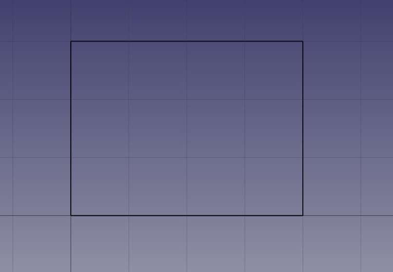
Notice that we consistently drew the lines in the same direction (clockwise). While this isn’t required, it helps ensure that the walls we will build next have consistent left and right orientations. You might wonder why we didn’t just draw a rectangle, which would have been simpler. However, using four separate lines gives us the opportunity to showcase additional BIM functionalities, such as how to combine multiple objects into one, which is an essential part of the workflow.
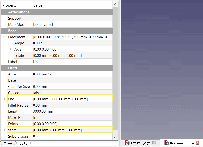
- Once you have created the lines check their start and end points and adjust if necessary to get them exactly correct.
- Select all four lines, then press the
 Wall button.
 - Set the walls' Height to 3m (default).
- Set Alignment property to left. Setting the Alignment property to the left ensures that the walls you create will be positioned to the left side of the lines you drew. In FreeCAD’s BIM Workbench, walls are typically generated based on a reference line, and the left or right alignment dictates which side of the line the wall will be placed.
If you didn’t draw the lines in the same order as instructed (clockwise), the orientation of some walls may be flipped, meaning they could be positioned on the opposite side of the line (to the right instead of the left). In that case, you would need to adjust the alignment to the right for those specific walls to ensure they all align consistently. Once this is set correctly, you'll have four walls that intersect at the corners, positioned on the inside of the baseline, forming the desired layout.
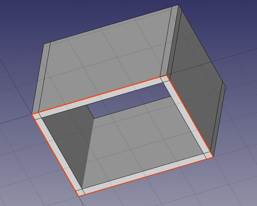
After creating walls, the next step is to join them so they intersect properly. This is necessary when walls don't connect cleanly at their intersections. To do this, you select one wall as the "host" and add the other walls as "additions", merging their geometry with the host. All objects in the BIM Workbench can have multiple additions (which add geometry) or subtractions (which remove geometry). These relationships can be managed anytime by double-clicking the object in the tree, allowing for flexible adjustments to ensure the walls and other architectural elements integrate smoothly.
- Select the four walls with Ctrl pressed, the last one being the wall that you chose to become the host
- Press the
 Add button. The four walls have now been turned into one:
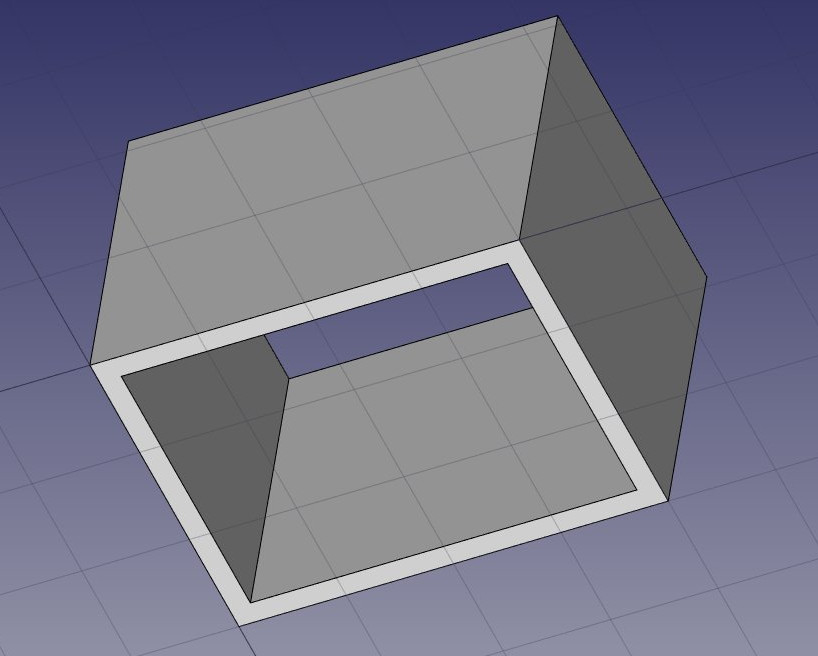
The individual walls are however still accessible, by expanding the wall in the tree view.
- Let's now place a door by pressing on the
 Door tool.
 - Begin by selecting the wall. While this step isn't required, it's a useful habit to develop. If an object is selected before starting an operation, the operation will automatically apply to that entity by default.
- Set the
 Working Plane to auto so we are not restricted to the ground plane
 - Press the Door button.
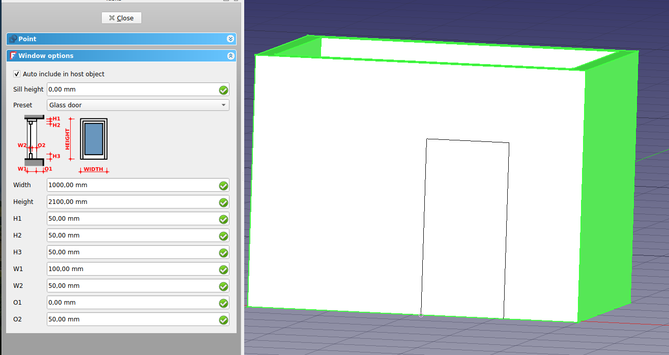
- In the door creation panel, select the Glass door preset, and set its Width to 1 m and its Height to 2.1m. You will notice that you can choose between various door types and set up their parameters as you wish. In FreeCAD a door is derived by an window operation.
- Make sure the
 Snap near option is turned on, so we can snap on faces
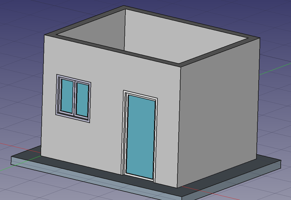
 - Place your door roughly on the middle of the front face of the wall:
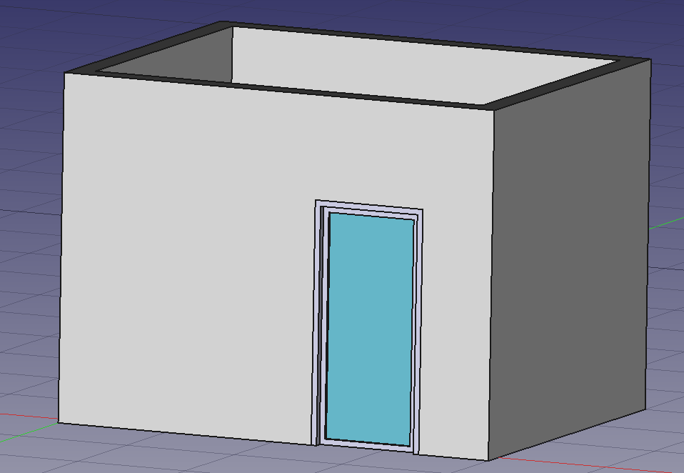
- We can now set the precise location by expanding the wall and the window objects in the tree view and changing the Placement property of the base sketch of our door. Set its position to x = 0.5 m, y = 0, z = 0. Our door is now exactly where we want it:
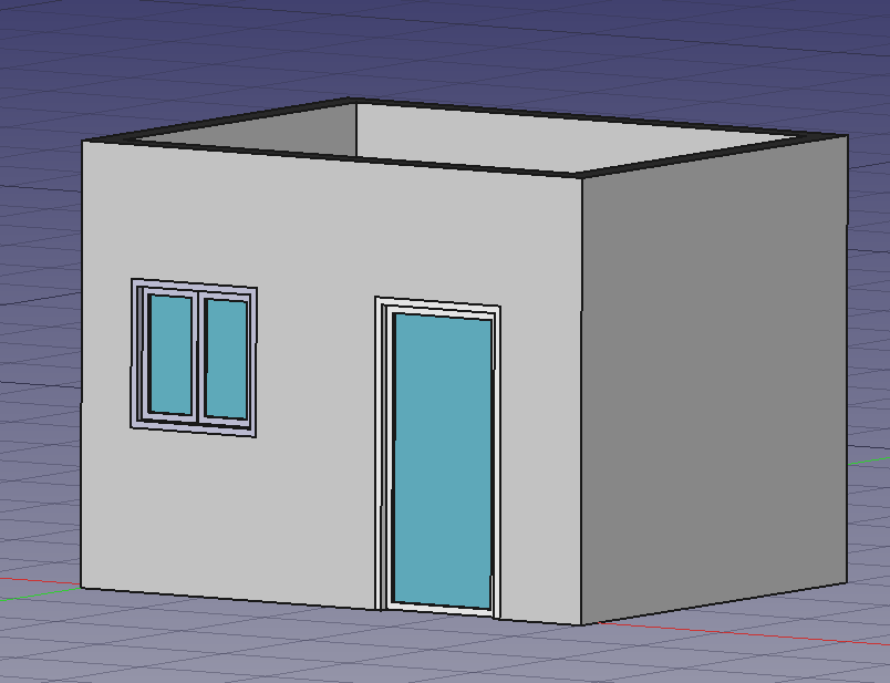
- Let's place a window next to our door. Select the wall, press the
 Window tool, select the Open 2-pane preset, and place a 1m x 1m window in the same face as the door. Set the placement of the underlying sketch to position x = 0, y = 0, z = 1.1m, so the upper line of the window is aligned to the top of the door.
Windows are always based on sketches. You can easily create custom windows by first drawing a sketch on a face, then turning that sketch into a window by selecting it and clicking the window button. Afterward, you can define the window's parameters—such as which parts of the sketch should be extruded and by how much—by double-clicking the window in the tree view. Now, let's move on to creating a slab:
- Set the Working Plane to XY plane
- Create a
 rectangle with a length of 5m, a height of 4m, and place it at position x:-0.5m, y:-0.7m, z:0.
 - Select the rectangle
- Click the
 Slab tool to create a slab from the rectangle
 - Keep the default values of 0.2m for the height property and set the normal direction to (0,0,-1), so the extrusion goes downward. While we could have moved the object 0.2m downward instead, it's a good practice to keep extruded objects aligned with their base profile to maintain consistency and accuracy in the model.
- Set the Ifc Type property of the slab to slab. This is not necessary in FreeCAD, but is important for IFC export, as it will ensure that the object is exported with the correct IFC type.
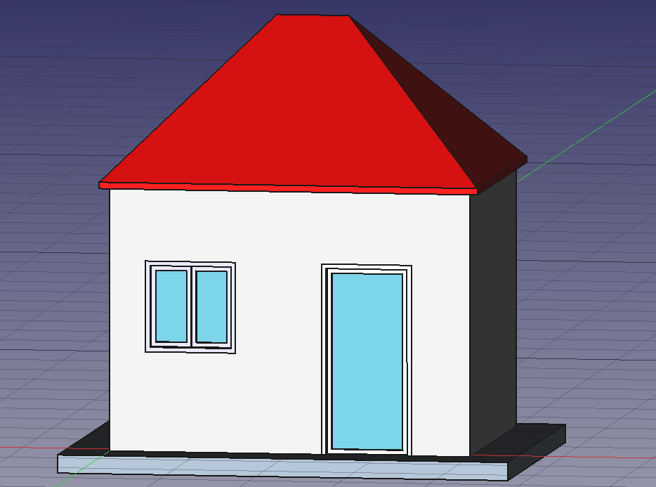
- Let's put a roof over our heads now. We can easily do it by using the
 Roof tool.
 - Press the
 Snap working plane option to enable the drafting on all planes.
 - By choosing one of the top faces of our house press the
 Select plane button. The working plane is now set to that face.
 - Create a rectangle, snapping to two opposite points of the walls:
- On the data tab of the roof set the Runs parameter to 1600.
- If you wish to change the color of the roof you can do so on the view tab
With that, our model is now complete. The next step is to organize it properly to ensure it exports correctly to the IFC format. IFC files require all building elements to be grouped within a building object, and optionally, within a specific story. Additionally, all buildings must be located on a site. However, FreeCAD's IFC exporter will automatically generate a default site if one isn't present, so we don't need to add it manually. It's important to properly structure the model to comply with IFC standards, ensuring smooth collaboration and compatibility with other BIM software. Proper organization will also help avoid any data loss or errors during the export process.
- Select the walls, the slab, and the roof.
- Press the
 Floor button
 - Select the floor we just created
- Press the
 Building button
Our model is now ready to export:
The IFC format is one of the most precious assets in a free BIM world, because it allows the exchange of data between any application and actor of the construction world, in an open manner (the format is open, free and maintained by an independent consortium). Exporting your BIM models as IFC ensures that anyone can see and analyze them, no matter the application used.
- Select the top object you want to export, that is, the Building object.
- Select menu File -> Export -> Industry Foundation Classes and save your file.
- The resulting IFC file can now be opened in a wide range of applications and viewers (the image below shows the file opened in the free IfcPlusPlus viewer). Checking the exported file in such a viewer application before distributing it to other people is important to check that all the data contained in the file is correct. FreeCAD itself can also be used to re-open the resulting IFC file.

We can use the ![]() TechDraw Workbench to create a drawing of our building. The process is similar to what was shown in the previous section, so we won't go into too much detail here. Simply create a new view by using the
TechDraw Workbench to create a drawing of our building. The process is similar to what was shown in the previous section, so we won't go into too much detail here. Simply create a new view by using the ![]() insert Default Page option, then select the view you want to display in the drawing and add dimensions where necessary. This will allow us to create a professional 2D representation of the 3D model for documentation or presentation purposes.
insert Default Page option, then select the view you want to display in the drawing and add dimensions where necessary. This will allow us to create a professional 2D representation of the 3D model for documentation or presentation purposes.

Our page is now ready, and we can export it to SVG or DXF formats, or print it. The SVG format allows you to open the file using illustration applications such as Inkscape, with which you can quickly enhance technical drawings and turn them into much nicer presentation drawings. It offers many more possibilities than the DXF format.
Downloads
- The file produced during this exercise: https://github.com/yorikvanhavre/FreeCAD-manual/blob/master/files/house.FCStd
- The IFC file exported from the above file: https://github.com/yorikvanhavre/FreeCAD-manual/blob/master/files/house.ifc
- The SVG file exported from the above file: https://github.com/yorikvanhavre/FreeCAD-manual/blob/master/files/house.svg
Related
- BIM Workbench
- The Arch Workbench
- The Draft working plane
- The Draft snapping settings
- The expressions system
- The IFC format
- IfcOpenShell
- IfcPlusPlus
- Inkscape
- 2D drafting: Sketch, Line, Polyline, Circle, Arc, Arc by 3 points, Fillet, Ellipse, Polygon, Rectangle, B-spline, Bézier curve, Cubic Bézier curve, Point
- 3D/BIM: Project, Site, Building, Level, Space, Wall, Curtain Wall, Column, Beam, Slab, Door, Window, Pipe, Pipe Connector, Stairs, Roof, Panel, Frame, Fence, Truss, Equipment
- Reinforcement tools: Custom Rebar, Straight Rebar, U-Shape Rebar, L-Shape Rebar, Stirrup, Bent-Shape Rebar, Helical Rebar, Column Reinforcement, Beam Reinforcement, Slab Reinforcement, Footing Reinforcement
- Generic 3D tools: Profile, Box, Shape builder..., Facebinder, Objects library, Component, External reference
- Annotation: Text, Shape from text, Aligned dimension, Horizontal dimension, Vertical dimension, Leader, Label, Axis, Axes System, Grid, Section Plane, Hatch, Page, View, Shape-based view
- Snapping: Snap lock, Snap endpoint, Snap midpoint, Snap center, Snap angle, Snap intersection, Snap perpendicular, Snap extension, Snap parallel, Snap special, Snap near, Snap ortho, Snap grid, Snap working plane, Snap dimensions, Toggle grid, Working Plane Top, Working Plane Front, Working Plane Side
- Modify: Move, Copy, Rotate, Clone, Create simple copy, Make compound, Offset, 2D Offset..., Trimex, Join, Split, Scale, Stretch, Draft to sketch, Upgrade, Downgrade, Add component, Remove component, Array, Path array, Polar array, Point array, Cut with plane, Mirror, Extrude..., Difference, Union, Intersection
- Manage: BIM Setup..., Views manager, Manage project..., Manage doors and windows..., Manage IFC elements..., Manage IFC quantities..., Manage IFC properties..., Manage classification..., Manage layers..., Material, Schedule, Preflight checks..., Annotation styles...
- Utils: Toggle bottom panels, Move to Trash, Working Plane View, Select group, Set slope, Create working plane proxy, Add to construction group, Split Mesh, Mesh to Shape, Select non-manifold meshes, Remove Shape from Arch, Close Holes, Merge Walls, Check, Toggle IFC Brep flag, Toggle subcomponents, Survey, IFC Diff, IFC explorer, Create IFC spreadsheet..., Image plane, Unclone, Rewire, Glue, Reextrude
- Panel tools: Panel, Panel Cut, Panel Sheet, Nest
- Structure tools: Structure, Structural System, Multiple Structures
- IFC tools: IFC Diff..., IFC Expand, Make IFC project, IfcOpenShell update
- Nudge: Nudge Switch, Nudge Up, Nudge Down, Nudge Left, Nudge Right, Nudge Rotate Left, Nudge Rotate Right, Nudge Extend, Nudge Shrink
- Additional: Preferences, Fine tuning, Import Export Preferences, IFC, DAE, OBJ, JSON, 3DS, SHP