Std TransformManip
|
|
| Menu location |
|---|
| Edit → Transform |
| Workbenches |
| All |
| Default shortcut |
| None |
| Introduced in version |
| - |
| See also |
| Std UserEditMode |
Description
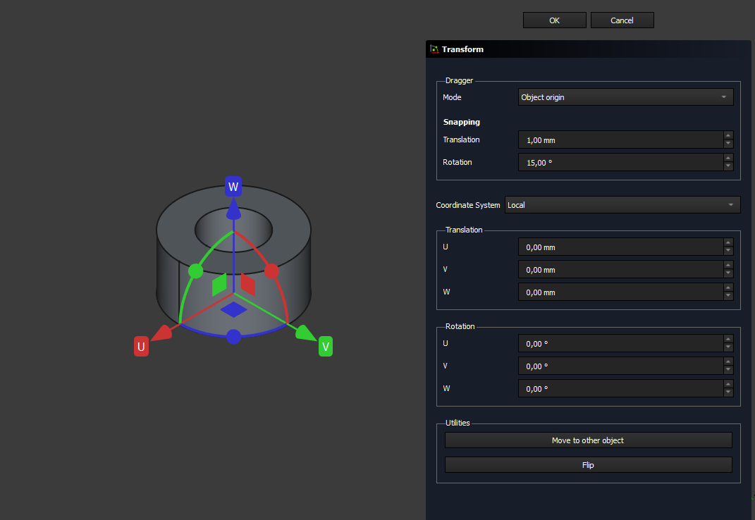
The Std TransformManip command allows you to apply rotation increments and translation increments to a selected object. This can be done either by dragging the interactive dragger in the 3D View or, introduced in 1.1, by entering precise values in the task panel, either in any (local) dragger coordinate system or the global coordinate system.
It is also possible to align the object at the dragger to a target element in the document while limiting translation or rotation to any axis selection.
Usage
- Select an object with a DataPlacement property. See Notes.
- There are several ways to invoke the command:
- The Transform task panel opens.
- Optionally adjust the snapping parameters: These are values for snapping to increments when dragging in the 3D View, either for rotation or translation.
- Do one or more of the following:
- Press and hold the left mouse button on an axis arrow and drag to translate the object along that axis.
- Press and hold the left mouse button on a plane and drag to translate the object along that plane.
- Press and hold the left mouse button on a sphere and drag to rotate the object around that axis.
- Optionally, adjust the location of the dragger, coordinate system, input precise delta (local), or absolute (global) increments, or move the object to a target object. introduced in 1.1. See the following Options section for more information.
- Do one of the following:
- Press the OK button to confirm and finish the command.
- Press the Cancel button to revert the applied transformations and finish the command. introduced in 1.0
Options
There are new options introduced in 1.1 for the tool. By default, the options are set to work the same as in version 1.0 and below.
You can adjust the following options:
Dragger
This section controls the interactive dragger (gizmo or axis handles) location and orientation, and its behavior in the 3D View. The object is always transformed around the current dragger coordinate system.
Mode
Allows to adjust the location and orientation of the dragger and therefore the transform origin.
- Object origin (default): Places the dragger at the origin of the object to be transformed.
- Center of mass / Centroid: Places the dragger at the centroid (geometric center) of the object to be transformed, which is only equal to the center of mass if the material is identical and equally distributed, or not considered.
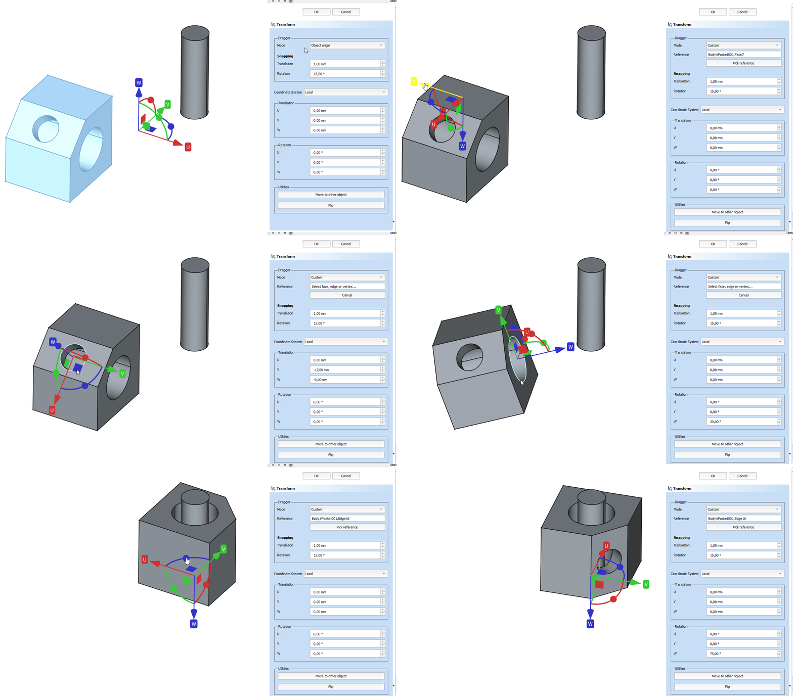
- Custom: The dragger can be snapped to any element in the document, not limited to the object to be transformed (faces, edges, vertices, datums). Choosing Custom waits for a user input, to place the dragger at a custom location. Hovering elements in the document previews the new dragger location and orientation, a click on the selection attaches the dragger at this position.
- Reference (only visible in Custom mode): Displays the element where the dragger (transform origin) is set to. It displays Select face, edge or vertex… if the tool waits for an input (selection) from the user.
- Pick Reference / Cancel (only visible in Custom mode): If a custom dragger location is set, Pick Reference allows the user to change the location of the dragger and snap it to a different element in the document. The object can be transformed, the dragger location be changed and transformed again, all in one active task. Cancel is displayed when the transform tool expects a user input for a new dragger location (selection in the 3D View) and cancels the placement of a custom dragger location.
Snapping
Snapping increments are values to control solely the interactive dragging behavior in the 3D View. The object to be transformed snaps to the following increments:
- Translation: Length value - snapping increment for translational change of the object in the 3D View, either in one axis or planar.
- Rotation: Angle value - snapping increment for a rotational change of the object in the 3D View around any axis.
If 0 is set as snapping increment, snapping is deactivated when dragging in the 3D View.
Coordinate system
This dropdown sets the coordinate system for the manual inputs in the task panel. The coordinate system has no effect when transforming the object solely by dragging in the 3D View (except when choosing Global and check to align the dragger rotation to the selected coordinate system.)
The axis labels are also displayed on the dragger in the 3D View, whereas U, V, W is the local coordinate system at the current dragger location, and X, Y, Z is the global coordinate system (equal to the placement value in the Property View, if the dragger is at the object's origin).
- Local (default): the current dragger location and orientation defines the transform origin for the following inputs in the task panel in U, V, W. The input is equal the delta to the current dragger location in its axes.
- Global: the task panel shows the values of the global position and rotation in the global coordinate system X, Y, Z and allows to change these values. If the dragger mode is set to Object origin, the values are the same as in the placement property of the object to be transformed.
- Align dragger rotation with selected coordinate system (default FALSE, only available if the coordinate system is not the local one): changes the orientation of the dragger to match the global axes X, Y, Z. The dragger location is not changed by this checkbox, only the axis rotation of the dragger. This allows to drag the object in the directions of the global axes (X, Y, Z), even if the object's origin is in a different orientation.
Translation
Length input for changing the translation of the object around the current dragger (transform origin).
- U, V, W (default, in local coordinate system): Allows to input – or displays, when dragging in the 3D View – the delta to the previous dragger location in the local coordinate system (= dragger location). The translation values in U, V, W are accumulated, as long as the dragger rotation (orientation of the axes) is not changed (either by dragging in the 3D View or by inputting rotation values in the task panel), the dragger is re-aligned to a different custom location, or the Move to Other Object function has been used. In these cases, the values are set to zero in the user interface of the task panel, without changing the actual translation of the object.
- X, Y, Z (in global coordinate system): Allows to input – or displays, when dragging in the 3D View – the location values of the current dragger position in the global coordinate system X, Y, Z. If the dragger mode is set to Object origin, the values correspond with the placement values of the object to be transformed which are also visible in the property view.
Rotation
Angular input for changing the rotation of the object around the current dragger (transform origin).
- U, V, W (default, in local coordinate system): Allows to input – or displays, when dragging in the 3D View – the delta to the previous dragger orientation in the local coordinate system (= dragger orientation). The rotation values in U, V, W are accumulated, as long as the dragger location (position of the axes) is not changed (either by dragging in the 3D View or by inputting translation values in the task panel), the dragger is re-aligned to a different custom location, or the Move to Other Object function has been used. In these cases, the rotation values are set to zero in the user interface of the task panel, without changing the actual rotation of the object.
- X, Y, Z (in global coordinate system): Allows to input – or displays, when dragging in the 3D View – the location values of the current dragger orientation in the global coordinate system in euler angles around X, Y, Z. If the dragger mode is set to Object origin, the values correspond with the rotational placement values of the object to be transformed.
Utilities
Quick actions to transform the selected object.
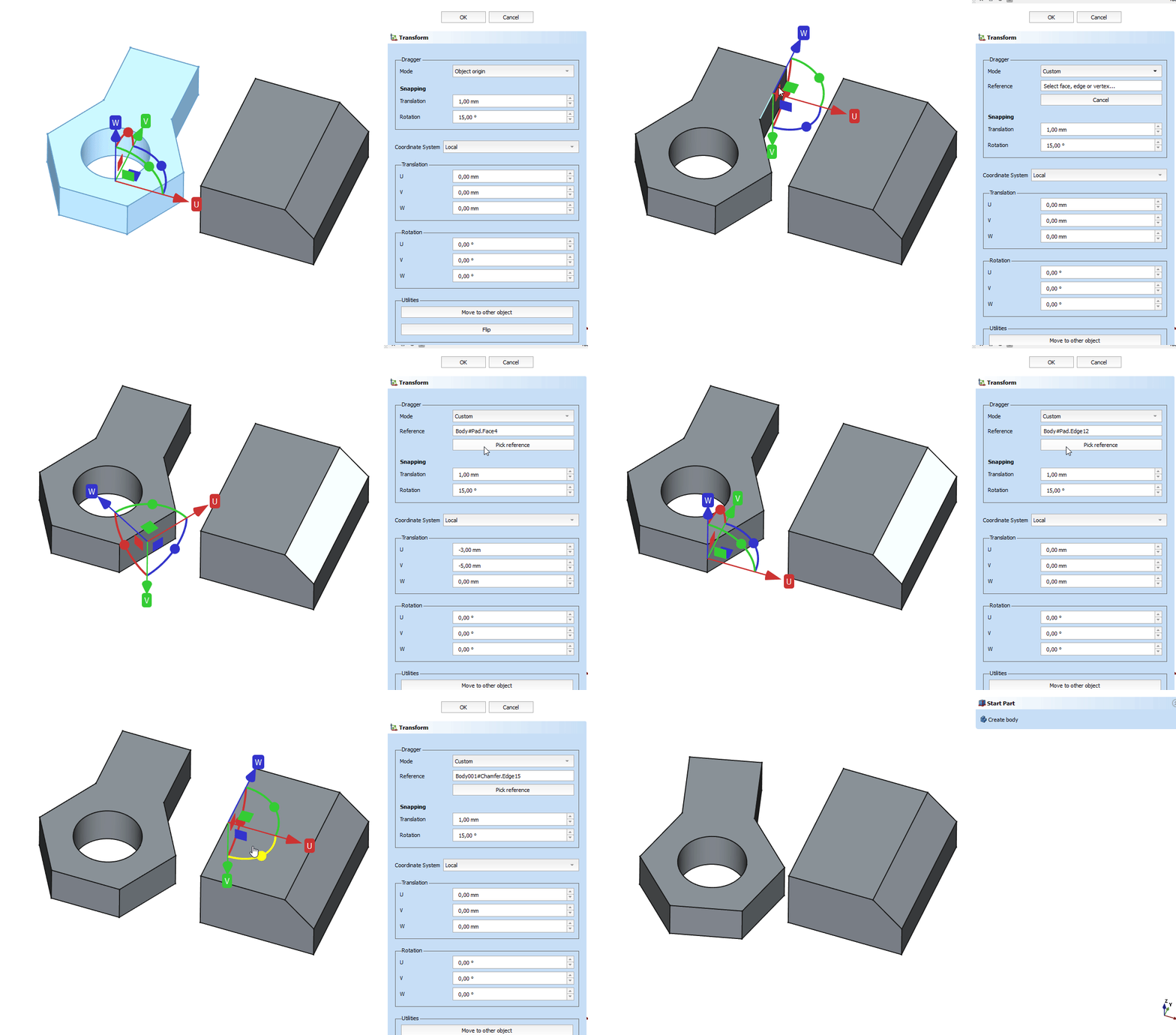
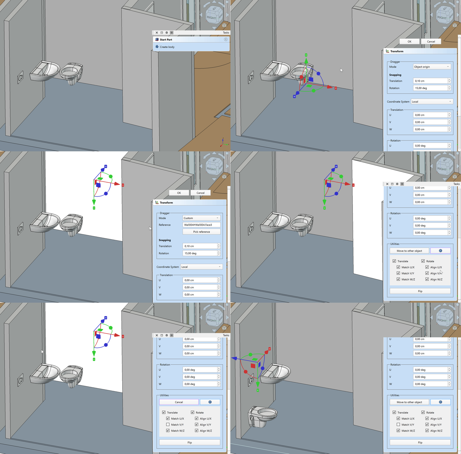
- Move to Other Object: Allows to interactively select a target location in the 3D View (any element in the document) where the object to be transformed is set to (translation and rotation), at the current dragger location. The button changes to Cancel if the tool waits for an input (3D selection) from the user. Cancel then aborts the selection of a target but does not close the transform tool. See examples below.
: Allows to specify the relevant axis components for the Move to Other Object command. By default, all translation and rotation axes are checked, translating and rotating the object from its dragger coordinate system to be moved to and aligned with the target location dragger coordinate system. Either translation or rotation can be locked, or individual axes can be chosen to be matched/aligned. For example an object can just be rotated to be aligned to a chosen face / object without moving it or the object can be moved to only match one or two axes with or without rotating the object to the target orientation. See advanced examples below.
- Flip: Flips the orientation of the object to be transformed 180 degrees around X and Z-axis. This is helpful, if after Move to Other Object the object to be transformed is intersecting the target object, because the target location coordinates are flipped 180 degrees.
Notes
- As soon as you rotate/move the object in the 3D View, changes are applied (only in 1.0 and below).
- Some objects with a DataPlacement property, such as sketches, cannot be manipulated, neither can objects that are attached to other objects.
- There is no Cancel button in 0.21 and below, in those versions you can press the OK button and use the
Undo command to revert changes afterwards.
Examples
Pick custom dragger
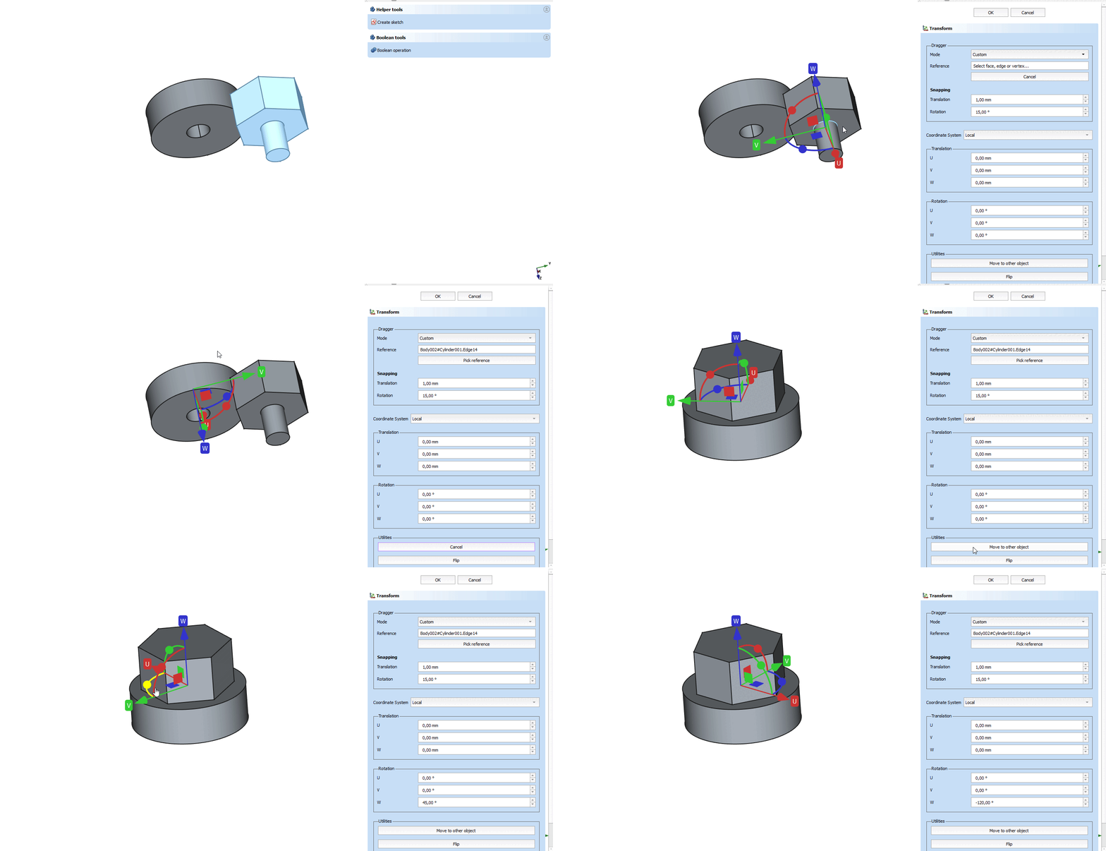
If the dragger is not in view or at an unwanted location, it can be set to either the center of mass or any element in the document (not limited to the object to be transformed):
- Invoke the Transform tool.
- Choose Dragger → Mode → Custom.
- Select any element in the 3D View.
- Transform around that dragger origin by either dragging in the 3D View, or changing the values in the task panel.
Demo animation (Click the image, if the animation does not start):
Center feature to global origin
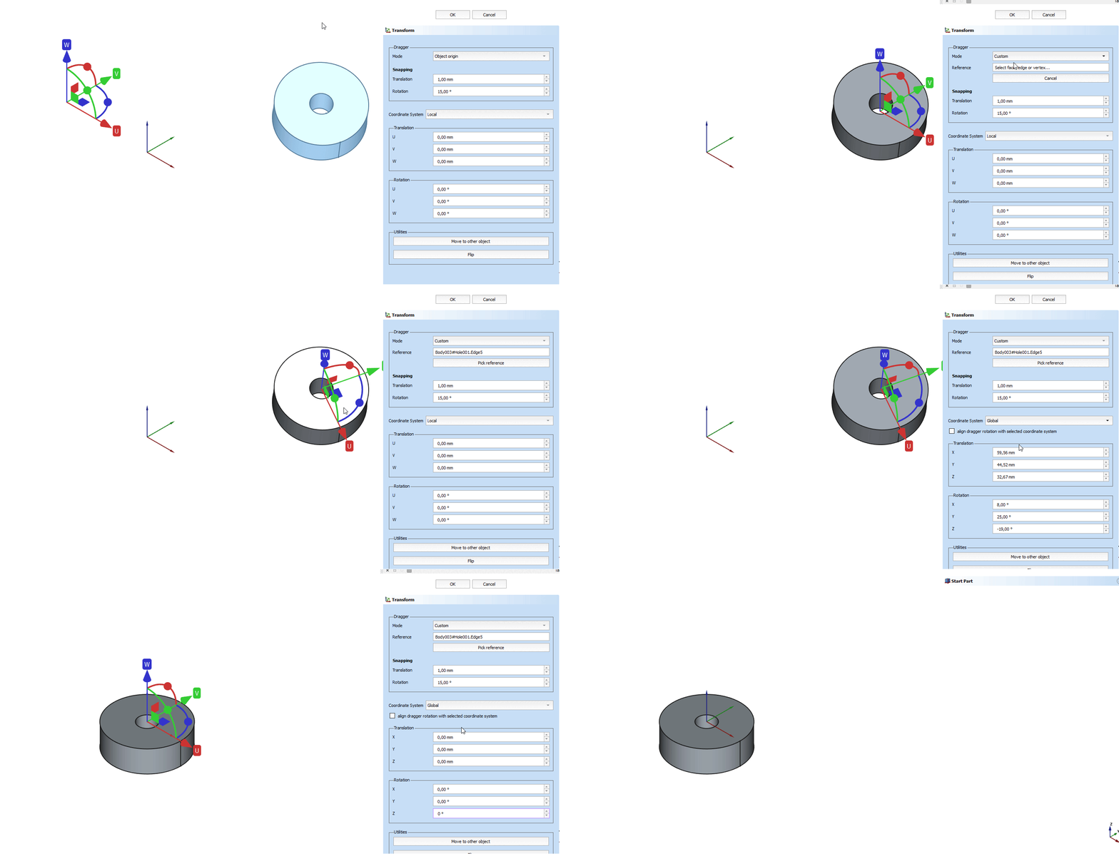
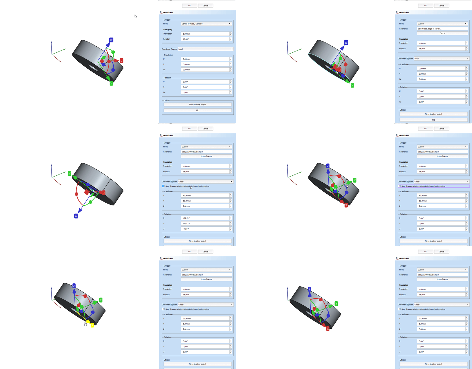
This allows to position bodies and imported STEP files with regard to special features (e.g. holes) in the document:
- Invoke the Transform tool.
- Choose Dragger → Mode → Custom.
- Select the element in the 3D View which needs to be positioned.
- Change the Coordinate system to Global.
- Input the new position, e.g. 0,0,0 to center the object to be transformed at the dragger location to the global origin.
Demo animation (Click the image, if the animation does not start):
Align to target object
If an object should be transformed to be placed at a target location (reference):
- Invoke the Transform tool.
- Choose Dragger → Mode → Custom.
- Select the reference element in the 3D View.
- Click Utilities → Move to Other Object.
- Select the target location (location where the object to be transformed is aligned to, at the current dragger position).
- Optional: click Flip to change the orientation, if the objects are intersecting.
Demo animation (Click the image, if the animation does not start):
Drag in global coordinate system if object is not aligned
If an (imported or transformed) object is not aligned to the global coordinate system X, Y, Z but it needs to be dragged (rotation or translation) around the global axes:
- Invoke the Transform tool.
- Optional: change dragger location Mode.
- Select the reference element in the 3D View.
- Change the Coordinate system to Global.
- Check the option Align dragger rotation with selected coordinate system.
- The labels on the dragger change from U, V, W to X, Y, Z and are now aligned to the global coordinate system.
Demo animation (Click the image, if the animation does not start):
Move BIM objects in custom directions
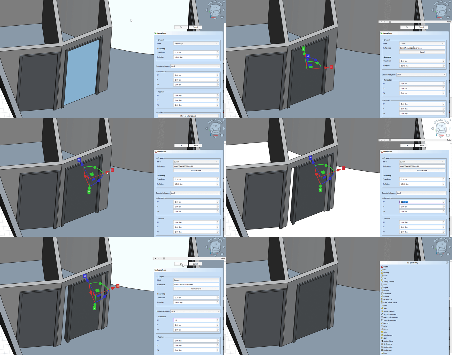
For example to move a BIM door along a skewed wall element:
- Invoke the Transform tool.
- Choose Dragger → Mode → Custom.
- Select an element which is oriented in the target direction.
- Transform around that dragger origin by either dragging in the 3D View, or changing the values in the task panel.
Demo animation (Click the image, if the animation does not start):
Advanced: Custom alignment of axes components
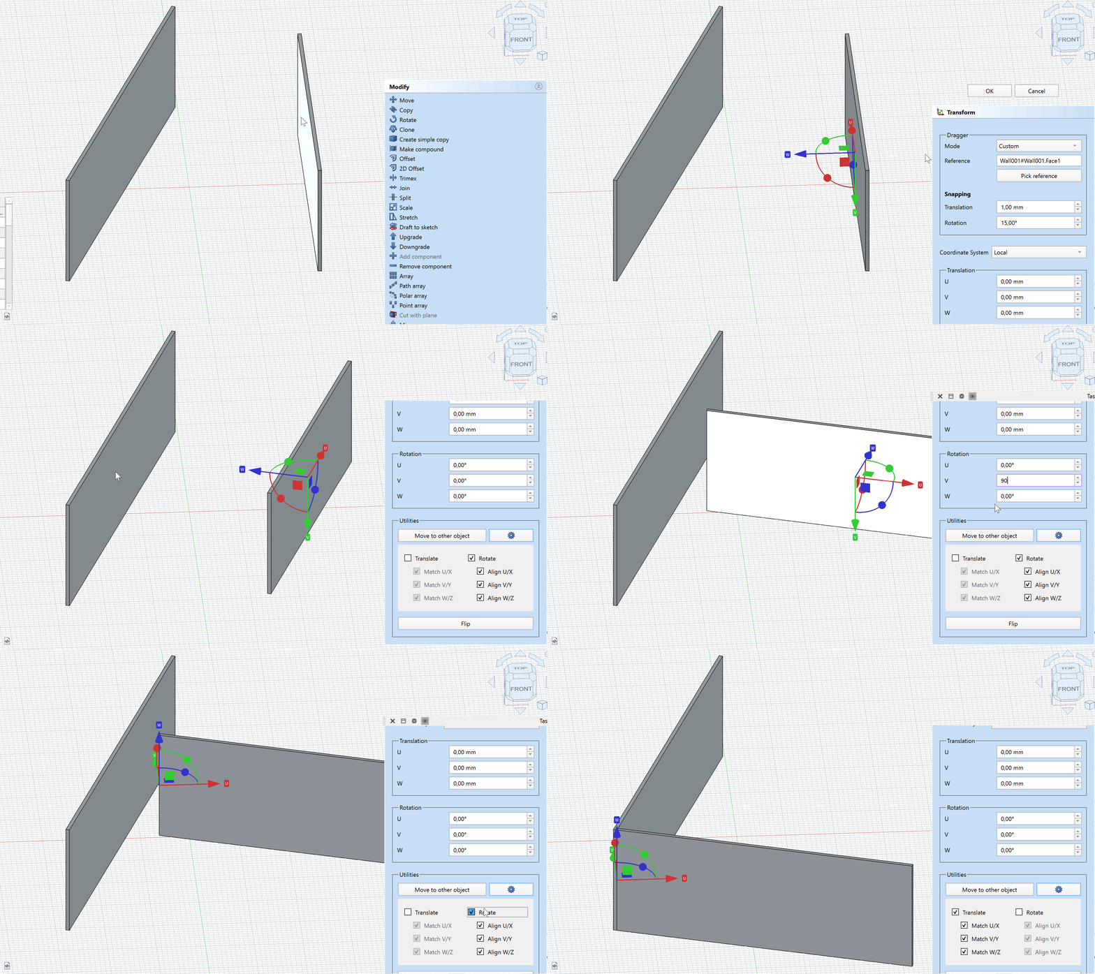
In the advanced settings of the Move to Other Object command it can be specified if the transform should consider translation or rotation in all or only some axes. This allows to align an object without moving it to other elements in the document, or move it to a target location without rotation:
- Invoke the Transform tool.
- Choose Dragger → Mode → Custom.
- Select any element in the 3D View.
- Open the advanced settings by clicking on the
button.
- Uncheck Translation to only rotate the object around the custom dragger coordinate system to match the target orientation.
- Click Utilities → Move to Other Object.
- Select the target object to be aligned to.
- Further adjust the rotation around one local axis to make the wall perpendicular.
- Choose Dragger → Mode → Reference → Pick Reference to choose a new reference position for the dragger and select the edge.
- In the advanced settings, check Translation and uncheck Rotation to only move the object from the custom dragger coordinate system to match the target location.
- Click Utilities → Move to Other Object and select the target edge.
Demo animation (Click the image, if the animation does not start):
Advanced: Lock translation in one axis
This examples aligns (rotates) and positions the object to a target location without changing the vertical position of the object:
- Invoke the Transform tool.
- Choose Dragger → Mode → Custom.
- Select any element in the 3D View.
- Open the advanced settings by clicking on the
button.
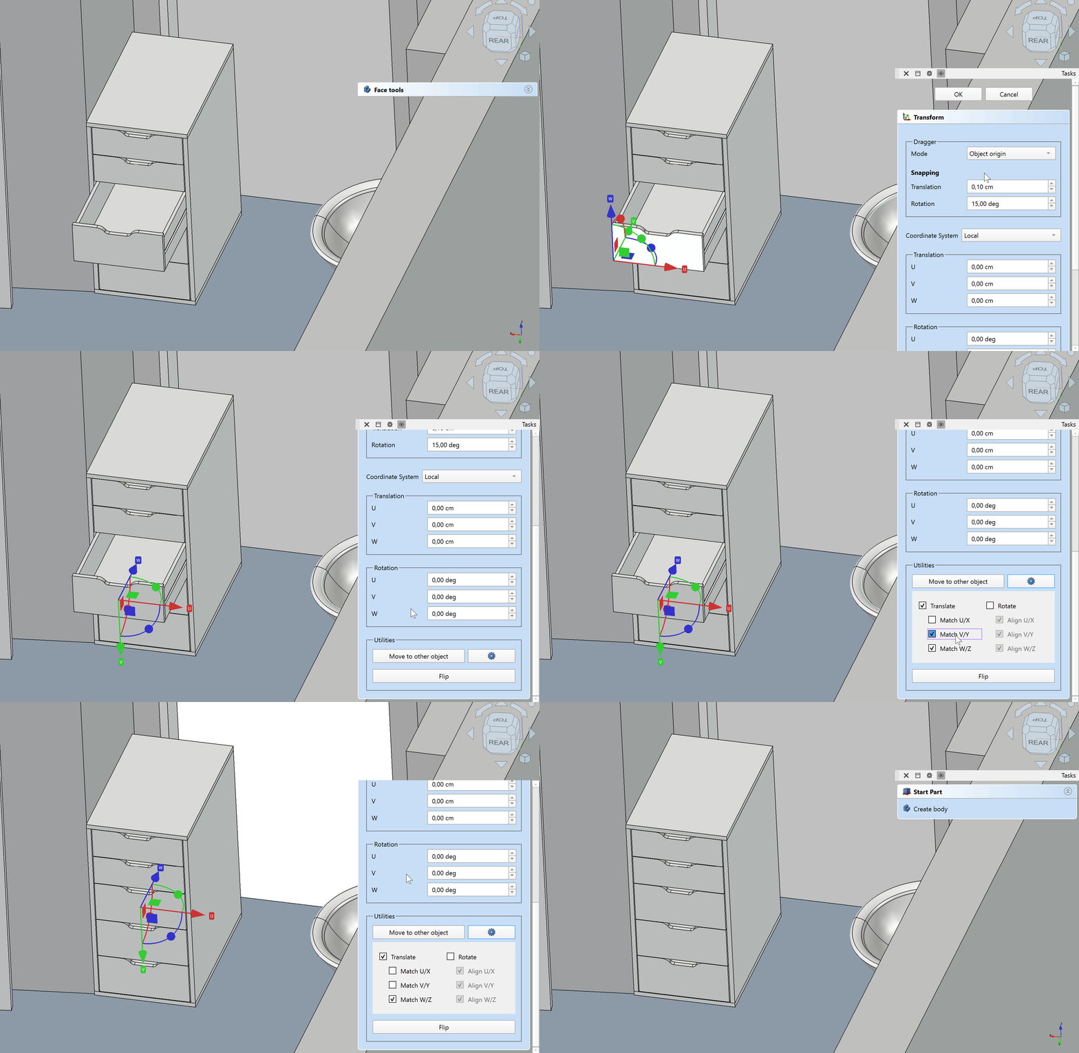
- Uncheck Match V/Y to lock the object's movement around the custom dragger V axis.
- Click Utilities → Move to Other Object.
- Select the target object to be aligned to.
- The object is aligned in all axes and moved in local U and W axis but the V axis component was not changed, resulting in the same vertical position on the object.
Demo animation (Click the image, if the animation does not start):
Advanced: Only match position of one axis
This examples moves the object in only one axis to a target location without changing other axes or rotation:
- Invoke the Transform tool.
- Choose Dragger → Mode → Custom.
- Select any element in the 3D View.
- Open the advanced settings by clicking on the
button.
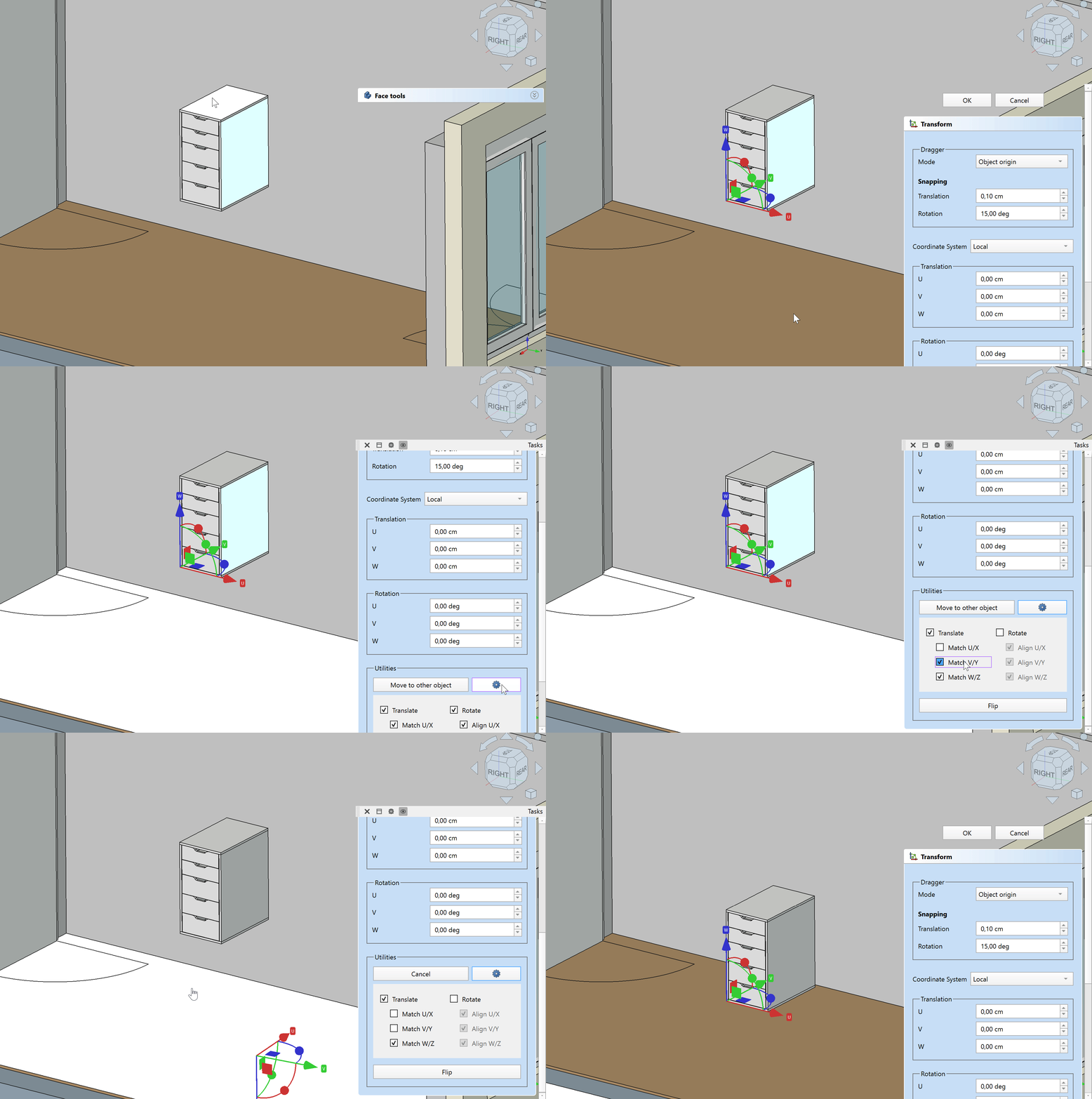
- Uncheck everything, except Match W/Z to only adjust the object's movement around the custom dragger W axis.
- Click Utilities → Move to Other Object.
- Select the target object to be aligned to.
- The object is moved only in the local W axis to the selected target location without changing any other position or rotation.
Demo animation (Click the image, if the animation does not start):
- File: New Document, Open, Open Recent, Close, Close All, Save, Save As, Save Copy, Save All, Revert, Import, Export,Merge Document, Document Information, Print, Print Preview, Export PDF, Exit
- Edit: Undo, Redo, Cut, Copy, Paste, Duplicate Object, Recompute, Box Selection, Box Element Selection, Select All, Delete, Send to Python Console, Placement, Transform, Align To, Toggle Edit Mode, Properties, Edit Mode, Preferences
- View:
- Miscellaneous: New 3D View, Orthographic View, Perspective View, Fullscreen, Bounding Box, Toggle Axis Cross, Clipping View, Texture Mapping, Toggle Navigation/Edit Mode, Material, Appearance, Random Color, Appearance per Face, Toggle Transparency, Workbench, Status Bar
- Standard Views: Fit All, Fit Selection, Align to Selection, Isometric, Dimetric, Trimetric, Home, Front, Top, Right, Rear, Bottom, Left, Rotate Left, Rotate Right, Store Working View, Recall Working View
- Freeze Display: Save Views, Load Views, Freeze View, Clear Views
- Draw Style: As Is, Points, Wireframe, Hidden Line, No Shading, Shaded, Flat Lines
- Stereo: Stereo Red/Cyan, Stereo Quad Buffer, Stereo Interleaved Rows, Stereo Interleaved Columns, Stereo Off, Issue Camera Position
- Zoom: Zoom In, Zoom Out, Box Zoom
- Document Window: Docked, Undocked, Fullscreen
- Visibility: Toggle Visibility, Show Selection, Hide Selection, Select Visible Objects, Toggle All Objects, Show All Objects, Hide All Objects, Toggle Selectability
- Toolbars: File, Edit, Clipboard, Workbench, Macro, View, Individual Views, Structure, Help, Lock Toolbars
- Panels: Tree View, Property View, Model, Selection View, Python Console, Report View, Tasks, DAG View
- Overlay Docked Panel: Toggle Overlay for All Panels, Toggle Transparent Panels, Toggle Overlay, Toggle Transparent Mode, Bypass Mouse Events in Overlay Panels, Toggle Left, Toggle Right, Toggle Top, Toggle Bottom
- Link Navigation: Go to Linked Object, Go to Deepest Linked Object, Select All Links
- Tree View Actions: Sync View, Sync Selection, Sync Placement, Preselection, Record Selection, Single Document, Multi Document, Collapse/Expand, Initiate Dragging, Go to Selection, Selection Back, Selection Forward
- Tools: Addon Manager, Measure, Clarify Selection, Quick Measure, Units Converter, Load Image, Save Image, Text Document, View Turntable, Scene Inspector, Dependency Graph, Export Dependency Graph, Document Utility, Edit Parameters, Customize
- Macro: Record Macro, Macros, Recent Macros, Execute Macro, Attach to Remote Debugger, Debug Macro, Stop Debugging, Step Over, Step Into, Toggle Breakpoint
- Help: What's This, Start Page, Users Documentation, FreeCAD Forum, Report an Issue, Restart in Safe Mode, Developers Handbook, Python Modules Documentation, FreeCAD Website, Donate to FreeCAD, About FreeCAD
- Additional:
- Miscellaneous: New Part, New Group, Variable Set, Link Group, Select All Instances, Toggle Freeze
- Datums: Coordinate System, Datum Plane, Datum Line, Datum Point
- Link Actions: Make Link, Make Sub-Link, Replace With Link, Unlink, Import Link, Import All Links
- Expression Actions: Copy Selected, Copy Active Document, Copy All Documents, Paste
- Selection Filter: Vertex Selection, Edge Selection, Face Selection, No Selection Filters
- Getting started
- Installation: Download, Windows, Linux, Mac, Additional components, Docker, AppImage, Ubuntu Snap
- Basics: About FreeCAD, Interface, Mouse navigation, Selection methods, Object name, Preferences, Workbenches, Document structure, Properties, Help FreeCAD, Donate
- Help: Tutorials, Video tutorials
- Workbenches: Std Base, Assembly, BIM, CAM, Draft, FEM, Inspection, Material, Mesh, OpenSCAD, Part, PartDesign, Points, Reverse Engineering, Robot, Sketcher, Spreadsheet, Surface, TechDraw, Test Framework
- Hubs: User hub, Power users hub, Developer hub
