Feature editing/ko
소개
이 페이지에서는 부품설계 작업대에서 도형특징의 편집 작업의 흐름를 설명합니다.
몸통(Body)
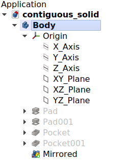
부품설계 작업대에서 작업하려면 먼저 몸통을 만들어야 합니다. 몸통(Body)은 하나의 연속된 고체(single contiguous solid)를 형성하는 일련의 특징들을 담는 그릇입니다. 몸통이 생성되면 표준 참조 평면(XY, XZ, YZ)과 축(X, Y, Z)으로 구성된 지역 좌표계인 원점 대상체가 자동으로 몸통에 추가됩니다. 각 도형특징은 누적되며 이전 도형특징의 결과에 더해지거나 빼집니다.
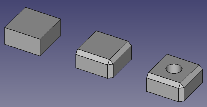
도형의 특징 누적. 왼쪽에서 오른쪽으로:
상자 특징이 담긴 몸통.
상자와 모따기 특징이 담긴 몸통.
상자, 모따기 및 오목자리 특징이 담긴 몸통.
문서에는 여러 개의 몸통이 포함될 수 있지만, 활성화할 수 있는 몸통은 하나뿐입니다. 새로운 도형 특징들은 활성화된 몸통에 추가됩니다. 나무 보기에서 몸통을 두 번 클릭하면 활성화하거나 비활성화할 수 있습니다. 활성화된 몸통은 나무 보기에 강조 표시됩니다.
연속된 고체란 무엇인가?
연속된 고체는 주조물이나 단일 금속 블록에서 가공된 것과 같은 물체입니다. 물체에 못, 나사, 접착제가 포함된 경우 단일 연속 고체가 아닙니다. 실제적인 예로, 나무 의자는 각 하위 구성요소(다리, 칸막이, 좌석 등)마다 하나씩 포함된 여러 몸통들로 구성됩니다.
프리캐드 버전 1.0에서는 몸통이 비인접 고체를 가질 수 있도록 하는 실험적 속성이 도입되었습니다. 새로 생성된 몸통의 기본값으로 기본 설정에서 설정할 수도 있습니다. 이것은 예시에서처럼 한 몸통의 의자를 만드는 데 사용되도록 의도된 것이 아닙니다. 이는 나중에 만들어지는 도형특징에 의해 연속적으로 생성될, 당장에는 분리된 고체를 생성할 수 있게 허용하기 위한 것입니다.
이전 나무 의자와 같이 모형에 여러 몸통들이 필요한 경우 범용 목적의 부품 그릇를 사용하여 몸통들을 모아 담고 전체를 하나의 단위로 이동할 수 있습니다.
몸통 가시성 관리
몸통은 기본적으로 가장 최근의 도형특징을 외부에 표시합니다. 이 도형특징은 몸통의 끝단(tip)입니다. 끝단에는 새로운 도형특징이 추가되는 위치도 표시됩니다. 임시로 끝단을 몸통 중간 임의 지점으로 다시 지정하여 해당 위치에 새로운 대상체(도형특징, 스케치 또는 기준 형상)를 삽입할 수 있습니다. 몸통에 새로운 특징이 추가되면서 이전 특징의 가시성은 꺼지고 새로운 새로운 특징이 끝단이 되어 표시됩니다.
한 번에 하나의 특징만 표시될 수 있습니다. 나무 보기에서 도형특징을 선택하고 Spacebar를 눌러 몸통내 도형특징의 가시성 전환을 할 수 있으며, 실제로 몸통의 특징생성 이력을 거슬러 올라갑니다. 도형특징의 가시성을 변경해도 몸통의 끝단은 변경되지 않습니다.
개체 이동 및 재정렬
몸통에 담긴 도형특징들을 재정렬하거나 다른 몸통으로 옮길 수 있습니다. 해당 도형특징을 선택하고 마우스 오른쪽 버튼을 클릭하면 두 가지 옵션을 모두 제공하는 상황에 맞는 메뉴가 나타납니다. 대상체가 소스 몸통에 종속되어 있는 경우(예: 면에 부착되어 있는 경우) 작업이 허용되지않을 수 있습니다. 스케치를 다른 몸통으로 이동하려면 외부 형상에 대한 링크가 포함되어서는 안 됩니다.
부품설계 작업 흐름의 개략도.
기준 도형
기준 도형은 사용자 정의 평면, 선, 점 또는 외부에 연결된 형상으로 구성됩니다. 스케치 및 특징에 대한 참조로 사용하기 위해 생성될 수 있습니다. 기준도형 대상체에는 다양한 부착 옵션이 있습니다.
프리캐드에서는 비표준 방향으로 스케치를 배치하는 경우 기준 평면이 적합합니다. 즉, 세 개의 주요 축을 중심으로 오프셋되거나 회전된 평면에서입니다. 하지만 스케치는 비표준 방향으로 배치될 수도 있고 기준 평면과 동일한 부착 옵션을 가질 수 있으므로, 스케치를 사용할 필요가 없는 경우가 많습니다. 동일한 비표준 방향을 갖는 스케치가 두 개 이상 있는 경우 기준 평면을 사용하는 것이 가장 합리적입니다. 기준 평면의 방향을 조정하면 연관된 모든 스케치와 해당 스케치에서 생성된 도형특징이 조정됩니다.
프리캐드 버전 1.0에는 이미 위상 명명 문제를 완화하는 코드가 있지만, 가능한 한 스케치와 기준 평면을 모두 몸통의 원점의 기본 평면에 부착하는 것이 여전히 가장 좋은 방법입니다. 생성된 형상(깔판이나 오목자리와 같은 작업의 결과 형상)을 참조하면 모형의 안전성이 떨어질 수 있습니다.아래의 안정적인 모형을 만들기 위한 조언 을 참조하세요.
안정적인 모형을 만들기 위한 조언
파라메트릭 모델링의 아이디어는 특정 매개변수의 값을 변경할 수 있고 후속 단계가 새 값에 따라 변경된다는 것을 의미합니다. 그러나 심각한 변경이 이루어지면 위상 명명 문제로 인해 모형이 깨져 버릴 수 있습니다. 다음 설계 원칙을 준수하면 깨짐을 최소화할 수 있습니다.
- 생성된 형상(모형 고체의 면, 모서리 또는 정점)에 스케치와 사용자 정의 기준 형상을 부착하지 마세요. 대신 표준 평면/축에 부착하세요. 표준 평면/축에 첨부된 스케치 또는 표준 평면/축에 첨부된 기준 도형에 첨부된 스케치는 예기치 않게 다른 참조에 다시 첨부되지 않습니다. 필요에 따라 부착 편차를 사용하십시오.
- "마스터 스케치"를 사용하세요. 마스터 스케치는 모형의 나머지 부분보다 먼저 작성되므로 표준 평면/축만 참조할 수 있습니다.
- 생성된 도형에서 (하위)형상 점착제를 생성하지 마세요. (하위)형상 점착제는 기반이 되는 스케치에서 도형이 삭제될 경우 문제가 될 수 있습니다.
- 생성된 형상보다는 스케치나 스케치 도형을 먼저 참조해 보세요. 생성된 도형을 불가피하게 참조해야 하는 경우, 참조할 요소가 있는 첫 번째 도형특징을 사용하세요. 그러면 이후 단계를 변경해도 모형이 손상되지 않습니다.
- 모깎기나 모따기와 같은 꾸밈적 특징은 가능한 한 모형특징 나무의 후반부에 사용하세요.
자습서
자습서 페이지에서는 부품설계 작업대의 특징 편집 방법을 사용하는 몇 가지 예를 제공합니다.
관련 문서
- Structure tools: Part, Group
- Helper tools: Create body, Create sketch, Attach sketch, Edit sketch, Validate sketch, Check geometry, Create a shape binder, Create a sub-object(s) shape binder, Create a clone, Create a datum plane, Create a datum line, Create a datum point, Create a local coordinate system
- Modeling tools:
- Additive tools: Pad, Revolution, Additive loft, Additive pipe, Additive helix, Additive box, Additive cylinder, Additive sphere, Additive cone, Additive ellipsoid, Additive torus, Additive prism, Additive wedge
- Subtractive tools: Pocket, Hole, Groove, Subtractive loft, Subtractive pipe, Subtractive helix, Subtractive box, Subtractive cylinder, Subtractive sphere, Subtractive cone, Subtractive ellipsoid, Subtractive torus, Subtractive prism, Subtractive wedge
- Boolean: Boolean operation
- Dress-up tools: Fillet, Chamfer, Draft, Thickness
- Transformation tools: Mirrored, Linear Pattern, Polar Pattern, Create MultiTransform, Scaled
- Extras: Sprocket, Involute gear, Shaft design wizard
- Context menu: Set tip, Move object to other body, Move object after other object, Appearance, Color per face
- Preferences: Preferences, Fine tuning
- Getting started
- Installation: Download, Windows, Linux, Mac, Additional components, Docker, AppImage, Ubuntu Snap
- Basics: About FreeCAD, Interface, Mouse navigation, Selection methods, Object name, Preferences, Workbenches, Document structure, Properties, Help FreeCAD, Donate
- Help: Tutorials, Video tutorials
- Workbenches: Std Base, Assembly, BIM, CAM, Draft, FEM, Inspection, Material, Mesh, OpenSCAD, Part, PartDesign, Points, Reverse Engineering, Robot, Sketcher, Spreadsheet, Surface, TechDraw, Test Framework
- Hubs: User hub, Power users hub, Developer hub

