PartDesign NewSketch/ko
|
|
| Menu location |
|---|
| 스케치 → 스케치 생성 |
| Workbenches |
| 부품설계 작업대 |
| Default shortcut |
| None |
| Introduced in version |
| 0.17 |
| See also |
| 스케치 작업대의 새 스케치 |
설명
이 도구는 새 스케치를 생성합니다. 아직 몸통이 없는 경우 스케치를 포함할 새 몸통을 생성한 후 스케치 작업대로 자동으로 전환합니다.
부품설계 작업대를 사용하여 모형을 생성할 때, 이 도구는 ![]() 스케치 작업대의 새 스케치 도구보다 선호됩니다.
스케치 작업대의 새 스케치 도구보다 선호됩니다.
용법
- 부품설계 작업대의 도구 모음에서
 스케치 생성 버튼을 누릅니다.
 - 작업 패널에 특징 선택(Select feature) 대화 상자가 나타납니다. 목록에서 평면 중 하나를 선택하거나 3D 보기에서 더 잘 보이도록 방향을 바꿀 수 있는 평면을 선택합니다.
- OK를 누릅니다.
- 인터페이스가 자동으로 스케치 작업대로 전환되고 스케치를 편집할 수 있습니다. 스케치가 종료되면 인터페이스가 다시 부품설계 작업대로 돌아가고 3D 보기는 스케치를 생성하기 전의 보기 방향으로 복원됩니다.
- 또는, 스케치를 생성하기 전에 기존 활성 몸통의 평면이나 면을 선택할 수 있으며, 이 경우 스케치가 즉시 생성됩니다.
선택 사항
- 기존 스케치의 부착을 변경하려면 해당 Map Mode 속성을 변경하세요(아래의 속성부분 참조).
- 특징 선택(Select feature) 대화상자는 새 스케치의 특징을 정의합니다.
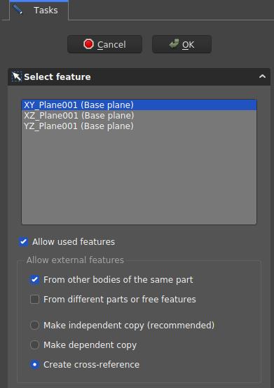
- 특징 선택(Select feature) 대화상자. 이러한 설정은 XY 평면에 스케치를 생성하고 동일한 몸통의 다른 항목과의 상호 참조를 허용합니다.

대화상자 설정
- 좌표계 상자: 스케치 평면의 방향을 정의합니다.
- Allow Used Features: TBD
- Allow external features options
- From other bodies of the same part: any elements used in the same body can be referenced
- From different parts or free features: TBD
- Make independent copy: all other elements will be separate copies, i.e. they will not change when the original changes.
- Make dependent copy: the elements will be copies, but a dependency to the original elements is kept. This is basically using a Shapebinder
- Create cross-reference: the linked elements will not be copies, but point to the original elements, e.g. a master sketch. Any changes are reflected to this sketch
스케치 작업대에서 어떠한 항목을 참조하려면 ![]() 외부 도형 및
외부 도형 및 ![]() 먹지 복사 도구를 사용합니다. 일반적으로 면이나 모서리 대신 다른 스케치를 참조용 원료로 사용하는 것이 좋습니다. 왜냐하면 위상학적 이름 지정 문제의 영향을 덜 받기 때문입니다.
먹지 복사 도구를 사용합니다. 일반적으로 면이나 모서리 대신 다른 스케치를 참조용 원료로 사용하는 것이 좋습니다. 왜냐하면 위상학적 이름 지정 문제의 영향을 덜 받기 때문입니다.
속성
- 데이터Map Mode: 스케치를 다른 객체(보통 평면이나 면이지만 다른 유형의 객체일 수도 있음)에 부착하는 모드입니다. 필드를 한 번 클릭하면 ... 버튼이 표시되고 해당 버튼을 눌러 부착 대화 상자를 엽니다. 비활성화됨으로 설정되면 배치 속성이 활성화됩니다.
- 데이터Placement: 3D 공간에서 스케치 방향을 제어합니다; 배치를 참조하세요. Map Mode 속성을 통해 스케치가 부착된 경우 비활성화됩니다.
- Helper tools: New Body, New Sketch, Attach Sketch, Edit Sketch, Validate Sketch, Check Geometry, Sub-Shape Binder, Clone
- Modeling tools:
- Additive tools: Pad, Revolution, Additive Loft, Additive Pipe, Additive Helix, Additive Box, Additive Cylinder, Additive Sphere, Additive Cone, Additive Ellipsoid, Additive Torus, Additive Prism, Additive Wedge
- Subtractive tools: Pocket, Hole, Groove, Subtractive Loft, Subtractive Pipe, Subtractive Helix, Subtractive Box, Subtractive Cylinder, Subtractive Sphere, Subtractive Cone, Subtractive Ellipsoid, Subtractive Torus, Subtractive Prism, Subtractive Wedge
- Boolean: Boolean Operation
- Dress-up tools: Fillet, Chamfer, Draft, Thickness
- Transformation tools: Mirror, Linear Pattern, Polar Pattern, Multi-Transform, Scale
- Additional tools: Shape Binder, Involute Gear, Sprocket, Shaft Design Wizard
- Context menu: Suppressed, Set Tip, Move Object To…, Move Feature After…
- Preferences: Preferences, Fine tuning
- Getting started
- Installation: Download, Windows, Linux, Mac, Additional components, Docker, AppImage, Ubuntu Snap
- Basics: About FreeCAD, Interface, Mouse navigation, Selection methods, Object name, Preferences, Workbenches, Document structure, Properties, Help FreeCAD, Donate
- Help: Tutorials, Video tutorials
- Workbenches: Std Base, Assembly, BIM, CAM, Draft, FEM, Inspection, Material, Mesh, OpenSCAD, Part, PartDesign, Points, Reverse Engineering, Robot, Sketcher, Spreadsheet, Surface, TechDraw, Test Framework
- Hubs: User hub, Power users hub, Developer hub