FEM ElementGeometry2D
|
|
| Menu location |
|---|
| Model → Element Geometry → Shell Plate Thickness |
| Workbenches |
| FEM |
| Default shortcut |
| C S |
| Introduced in version |
| - |
| See also |
| FEM tutorial |
| Solvers |
|---|
| All |
Description
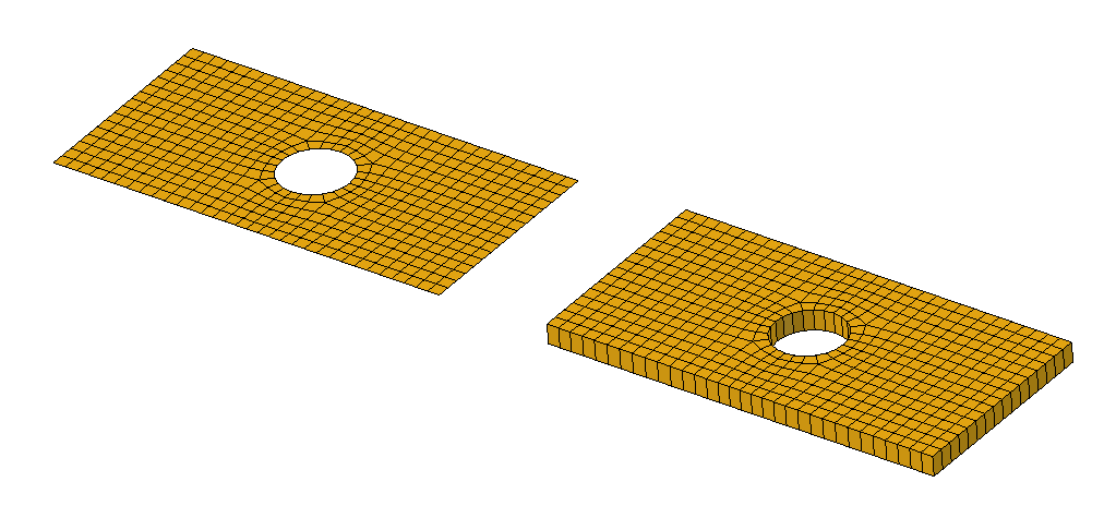
ElementGeometry2D is used to define the thickness of 2D (shell and introduced in 1.0: plane stress/strain) FEM elements, all or lying on the chosen surface. It has to be defined also for axisymmetric models, even though the thickness value is irrelevant in such a case.
2D mesh (on the left) and its expansion to solid elements done internally by CalculiX based on the specified thickness (on the right)
Usage
- There are several ways to invoke the command:
- Press the
Shell Plate Thickness button.
- Select the Model → Element Geometry →
Shell Plate Thickness option from the menu.
- Press the
- Specify the shell thickness.
- Optionally press the Add button in the task panel and then click on the face you want to have a prescribed thickness. If the face selection is empty, all the remaining faces (whose thickness is not defined by other FEM ElementGeometry2D objects) will be automatically assigned. introduced in 1.1: To remove faces from the selection, press the Remove button.
Limitations
- Currently, analyses combining shell elements with solid or edge (beam) elements are not supported.
Properties
- DataThickness: Specifies the thickness of the 2D elements.
- DataOffset - introduced in 1.1: Specifies offset of the shell mid-surface with respect to the meshed geometry. The unit is the shell thickness. Positive values indicate offset in the positive normal direction, negative values indicate offset in the opposite direction. Zero means no offset (mid-surface located on the meshed geometrical surface). For example, 0.5 means that the meshed geometrical surface will be the top surface of the expanded shell while -0.5 means that it will be the bottom surface.
Notes
- For viewing results from CalculiX solver on the mesh expanded to the prescribed thickness, the property
Beam Shell Result Output 3Din the FEM SolverCalculixCcxtools needs to be set toTrue. To just visualize the defined thicknesses before running actual calculations, one may run a check type analysis with this property set toTrue. - This feature uses the *SHELL SECTION card in CalculiX for shell elements and *SOLID SECTION card for plane stress/strain and axisymmetric elements.
- Materials: Solid, Fluid, Nonlinear mechanical, Reinforced (concrete); Material editor
- Element geometry: Beam (1D), Beam rotation (1D), Shell (2D), Fluid flow (1D)
Constraints
- Electromagnetic: Electrostatic potential, Current density, Magnetization
- Geometrical: Plane rotation, Section print, Transform
- Mechanical: Fixed, Displacement, Contact, Tie, Spring, Force, Pressure, Centrif, Self weight
- Thermal: Initial temperature, Heat flux, Temperature, Body heat source
- Overwrite Constants: Constant vacuum permittivity
- Solve: CalculiX Standard, Elmer, Mystran, Z88; Equations: Deformation, Elasticity, Electrostatic, Electricforce, Magnetodynamic, Magnetodynamic 2D, Flow, Flux, Heat; Solver: Solver control, Solver run
- Results: Purge, Show; Postprocessing: Apply changes, Pipeline from result, Warp filter, Scalar clip filter, Function cut filter, Region clip filter, Contours filter, Line clip filter, Stress linearization plot, Data at point clip filter, Filter function plane, Filter function sphere, Filter function cylinder, Filter function box
- Additional: Preferences; FEM Install, FEM Mesh, FEM Solver, FEM CalculiX, FEM Concrete; FEM Element Types
- Getting started
- Installation: Download, Windows, Linux, Mac, Additional components, Docker, AppImage, Ubuntu Snap
- Basics: About FreeCAD, Interface, Mouse navigation, Selection methods, Object name, Preferences, Workbenches, Document structure, Properties, Help FreeCAD, Donate
- Help: Tutorials, Video tutorials
- Workbenches: Std Base, Assembly, BIM, CAM, Draft, FEM, Inspection, Material, Mesh, OpenSCAD, Part, PartDesign, Points, Reverse Engineering, Robot, Sketcher, Spreadsheet, Surface, TechDraw, Test Framework
- Hubs: User hub, Power users hub, Developer hub
