Sketcher Preferences/de
Einleitung
Die Einstellungen für den Arbeitsbereich Sketcher befinden sich im Voreinstellungseditor. Im Menü wählt man Bearbeiten → Einstellungen... und dann
Sketcher. Diese Gruppe steht nur dann zur Verfügung, wenn der Arbeitsbereich Sketcher in der aktuellen FreeCAD-Sitzung geladen wurde
Es gibt vier Seiten: Allgemein, Raster, Anzeige und Darstellung.
Einige fortgeschrittene Einstellungen können nur im Parameter-Editor geändert werden. Siehe Feinabstimmung.
In 0.21 und davor hieß die Seite Darstellung noch "Farben".
Allgemein
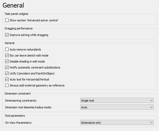
Auf dieser Seite "Allgemein" kann Folgendes festgelegt werden:
| Name | Beschreibung |
|---|---|
| Abschnitt 'Erweiterte Einstellungten des Lösers' anzeigen | Wenn aktiviert, wird im Sketcher-Dialog der Abschnitt Erweiterte Steuerung des Lösers angezeigt, in dem die Einstellungen des Lösers angepasst werden können. |
| Verbessert Lösen beim Ziehen | Wenn aktiviert, wird beim Ziehen von Skizzenelementen ein spezieller Lösungsalgorithmus verwendet. Dadurch wird verhindert, dass sich die Skizze beim Ziehen dreht. In den meisten Fällen ist dies eine Verbesserung, bei komplexen Skizzen kann diese Option jedoch die Zeit zum Lösen der Skizze verlängern. |
| Automatisches Entfernen überflüssiger Randbedingungen | Wenn aktiviert, werden redundante, neue Einschränkungen automatisch entfernt. |
| Mit Esc den Bearbeitungsmodus einer Skizze verlassen | Wenn aktiviert, ermöglicht es den Bearbeitungsmodus einer Skizze durch Drücken der Taste Esc zu verlassen. Deaktiviert kann es für Benutzer nützlich sein, die es gewohnt sind, Esc als Teil ihres Arbeitsablaufs in anderen CAD-Lösungen zu drücken, aber nicht unbedingt eine Skizze verlassen möchten. |
| Schattierung im Bearbeitungsmodus deaktivieren Nur in Version 1.0 verfügbar. | Wenn aktiviert, wird die schattierte Ansicht beim Aufrufen des Skizzenbearbeitungsmodus deaktiviert. |
| Benachrichtigung beim automatischen Ersetzen von Randbedingungen | Wenn aktiviert, wird in einem Dialogfeld über die Ersetzung von Randbedingungen informiert. Wenn beispielsweise die Endpunkte zweier Bögen mit der Koinzidenz-Randbedingung verbunden sind und die Bögen mit der Tangenten-Randbedingung neu verbunden werden, wird die Koinzidenz durch die Tangenten-Beschränkung ersetzt und es erscheint ein Popup-Dialog der darüber informiert. |
| KoinzidentFestlegen und PunkAufObjektFestlegen kombinieren eingeführt in 1.0 | Wenn aktiviert, werden die Randbedingungen KoinzidentFestlegen und PunktAufObjektFestlegen in einem einzigen Werkzeug kombiniert.
Nachdem diese Einstellung geändert wurde, muss FreeCAD neu gestartet werden. |
| Einheitliches Werkzeug für automatische horizontale/vertikale Beschränkungen eingeführt in 1.0 | Wenn diese Option aktiviert ist, wird das Werkzeug automatische horizontale/vertikale Beschränkungen zur Werkzeugleiste hinzugefügt (es ist immer im Menü und über seine Verknüpfung verfügbar), und die Werkzeuge Horizontal Festlegen und Vertikal Festlegen sind darunter in einem Dropdown-Menü gruppiert.
Nachdem diese Einstellung geändert wurde, muss FreeCAD neu gestartet werden. |
| Group the polyline and line commands eingeführt in 1.1 | Wenn diese Option aktiviert ist, wird eine Befehlsgruppen-Schaltfläche angezeigt, die sowohl die Polylinie als auch die Linie enthält. Andernfalls hat jeder Befehl eine eigene Schaltfläche.
Nachdem diese Einstellung geändert wurde, muss FreeCAD neu gestartet werden. |
| Always add external geometry as construction eingeführt in 1.1 | Wenn diese Option aktiviert ist, wird externe Geometrie immer als Konstruktionsgeometrie hinzugefügt, unabhängig vom aktuell eingestellten Konstruktionsmodus. |
| Interne Flächen erzeugen eingeführt in 1.1 | Wenn diese Option aktiviert ist, generieren geschlossene Schleifen automatisch interne Flächen, die ausgewählt und mit anderen Werkzeugen verwendet werden können. |
| Randbedingungen für Maßangaben eingeführt in 1.0 | Legt die Werkzeuge für Maßbeschränkungen für die Symbolleiste fest (alle Maßwerkzeuge sind immer im Menü und über ihre Tastenkombinationen verfügbar). Die Optionen sind:
Nachdem diese Einstellung geändert wurde, muss FreeCAD neu gestartet werden. |
| Maßwerkzeug Durchmesser-/Radiusmodus eingeführt in 1.0 | Legt fest, wie das kombinierte Sketcher Bemaßen mit Kreisen und Bögen umgeht. Deaktiviert, wenn die vorherige Einstellung auf Einzelne Werkzeuge gesetzt ist. Die Optionen sind:
|
| Skalierung bei erster Randbedingung eingeführt in 1.1 | Legt fest, wie die automatische Geometrieskalierung bei der ersten Dimensionierung durchgeführt wird:
|
| In-Ansicht-Parameter (OVP) introduced in 1.0 | Legt den Sichtbarkeitsmodus für die In-Ansicht-Parameter fest. Die Optionen sind:
|
Raster
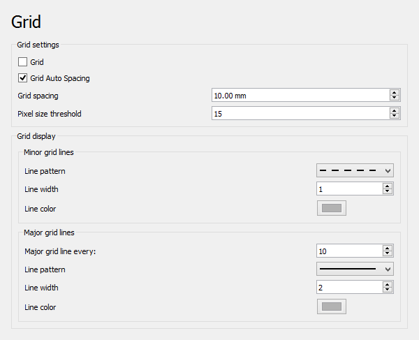
Auf dieser Seite kann Folgendes festgelegt werden:
| Name | Beschreibung |
|---|---|
| Raster | Wenn diese Option aktiviert ist, wird im Bearbeitungsmodus ein Raster angezeigt. Wird für neue Skizzen verwendet. Wird in der Eigenschaft Ansicht-EigenschaftShow Grid von Skizzen gespeichert. |
| Automatische Rasterweite | Wenn diese Option aktiviert ist, wird der Rasterabstand automatisch an die Ansichtsabmessungen angepasst. Wird für neue Skizzen verwendet. Wird in der Eigenschaft Ansicht-EigenschaftGrid Auto von Skizzen gespeichert. |
| Rasterweite | Der Abstand zwischen zwei aufeinanderfolgenden Rasterlinien. Wird als Basiswert verwendet, wenn Automatische Rasterweite aktiviert ist. Wird für neue Skizzen verwendet. Wird in der Eigenschaft Ansicht-EigenschaftGrid Size von Skizzen gespeichert. |
| Grenzwert für die Pixelgröße | Der Grenzwert für den Rasterabstand in Pixeln. Wird nur verwendet, wenn Automatische Rasterweite aktiviert ist. Wenn der Abstand auf dem Bildschirm kleiner als dieser Wert ist, wird der physische Rasterabstand mit dem Wert Haupt-Rasterlinien-Intervall multipliziert. Wenn der Abstand auf dem Bildschirm größer ist als der Schwellenwert multipliziert mit dem Wert Intervall, wird der physikalische Rasterabstand durch den Wert Intervall geteilt. Wenn der Wert Intervall auf 1 gesetzt ist, wird stattdessen 10 für diese Berechnungen verwendet. |
| Untergeordnete Rasterlinien | For minor grid lines you can specify:
|
| Haupt-Rasterlinien | Für Haupt-Rasterlinien kann Folgendes festgelegt werden:
|
Anzeige
Auf dieser Seite kann Folgendes festgelegt werden:
| Name | Beschreibung |
|---|---|
| Schriftgröße | Die für die Beschriftungen und Beschränkungen in der Skizze verwendete Schriftgröße. |
| Größe der Symbole für Randbedingungen eingeführt in 1.1 | Pixelgröße für Randbedingungssymbole. |
| Skalierungsverhältnis anzeigen eingeführt in 0.21 | Die 3D-Ansicht wird anhand dieses Faktors skaliert. |
| Segmente por Geometrie | Kurven werden zur Visualisierung durch Polygonsegmente approximiert. Dieser Wert definiert die Anzahl der Segmente. Die Untergrenze liegt bei 50 Segmenten. Höhere Werte verfeinern die Visualisierung, können jedoch zu längeren Berechnungszeiten führen, insbesondere bei B-Splines. |
| Wert erfragen, nach Erstellung einer maßlichen Randbedingung | Wenn diese Option aktiviert ist, wird ein Dialogfeld angezeigt, in dem einen Wert für neue Maßbeschränkungen eingeben werden kann. |
| Geometrie im „Fortsetzen-Modus“ erstellen | Wenn diese Option aktiviert ist, bleiben die Werkzeuge zur Geometrieerstellung nach dem Erstellen eines Elements aktiv. Ein Werkzeug kann jederzeit verlassen, indem mit der rechten Maustaste in die Skizze geklickt wird. |
| Randbedingungen im „Fortsetzen-Modus“ erstellen | Wenn diese Option aktiviert ist, bleiben die Werkzeuge zum Erstellen von Randbedingungen nach dem Erstellen einer Randbedingungen aktiv. Ein Werkzeug kann jederzeit verlassen werden, indem mit der rechten Maustaste in die Skizze geklickt wird. |
| Basislängeneinheiten für unterstützte Einheitensysteme ausblenden | Wenn diese Option aktiviert ist, wird die Längeneinheit aus dem ausgewählten Einheitensystem verwendet, aber nicht in den Skizzenbeschränkungen angezeigt. Nur für unterstützte Einheitensysteme. |
| Während der Bearbeitung die Koordinaten neben dem Mauszeiger anzeigen introduced in 0.21 | Wenn diese Option aktiviert ist, werden die Zeiger-Koordinaten während der Bearbeitung einer Skizze neben dem Zeiger angezeigt. |
| Benutze die Einstellung der Dezimalstellen des Systems für Zeiger-Koordinaten eingeführt in 0.21 | Wenn diese Option aktiviert ist, verwenden die Zeiger-Koordinaten die System-Dezimalstelle anstelle der Kurzform. |
| Name der maßlichen Randbedingung in Maßeinträgen anzeigen eingeführt in 0.21 | Wenn diese Option aktiviert ist, werden die Namen der Maßbeschränkungen (sofern verfügbar) im angegebenen Format angezeigt:
|
| Alle Objekte ausblenden, die von der Skizze abhängen | Wenn diese Option aktiviert ist, werden alle Objekte, die von der Skizze abhängen, beim Öffnen der Skizze ausgeblendet. Es muss beachtet werden, dass dies möglicherweise keine Auswirkungen hat, wenn die Optionen Für externe Geometrie verwendete Objekte anzeigen und/oder Objekte anzeigen, an denen die Skizze befestigt ist ausgewählt sind. |
| Objekte anzeigen, die für die externe Geometrie verwendet werden | Wenn diese Option aktiviert ist, werden versteckte Objekte, die für die externe Geometrie verwendet werden, beim Öffnen der Skizze angezeigt. |
| Objekte anzeigen, an denen die Skizze befestigt ist | Wenn diese Option aktiviert ist, werden versteckte Objekte, an die die Skizze angehängt ist, beim Öffnen der Skizze angezeigt. |
| Kameraposition nach der Bearbeitung wiederherstellen | Wenn diese Option aktiviert ist, wird die Kameraposition auf die Position zurückgesetzt, die sie vor dem Öffnen der Skizze hatte. |
| Orthogonale Kamera bei Aktivierung des Bearbeitungsmodus festlegen | Wenn diese Option aktiviert ist, wird der Kameramodus beim Öffnen der Skizze zwangsweise auf orthografisch gesetzt. Der Kameramodus wird beim Verlassen des Bearbeitungsmodus wiederhergestellt. Diese Einstellung ist nur verfügbar, wenn Kameraposition nach der Bearbeitung wiederherstellen aktiviert ist. |
| Skizze im Schnittansicht-Modus öffnen | Wenn diese Option aktiviert ist, wird die Skizze mit der aktiven „Schnittansicht“ geöffnet. |
| Auf vorhandene Skizzen anwenden | Wenn darauf geklickt wird, werden die Einstellungen unter Sichtbarkeitsautomatisierung auch auf vorhandene Skizzen angewendet. Andernfalls werden sie nur für neue Skizzen verwendet. |
Darstellung
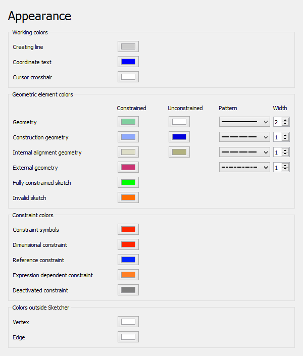
Sofern nicht anders angegeben, werden diese Einstellungen nur verwendet, wenn sich eine Skizze im Bearbeitungsmodus befindet.
Auf dieser Seite kann Folgendes festgelegt werden:
| Name | Beschreibung |
|---|---|
| Linie erstellen | Die Farbe, die für Skizzenelemente während ihrer Erstellung verwendet wird. |
| Koordinatentext | Die Farbe, die für die Koordinaten verwendet wird, die beim Erstellen von Skizzenelementen angezeigt werden. |
| Zeiger-Fadenkreuz | Die Farbe, die für den Fadenkreuz-Zeiger verwendet wird, der beim Erstellen von Skizzenelementen angezeigt wird. |
| Geometrie eingeführt in 1.0 | Die Farben, die für eingeschränkte und uneingeschränkte normale Geometrie verwendet werden. Das Linienmuster und die Linienbreite können ebenfalls festgelegt werden. |
| Hilfsgeometrie | Die Farben für eingeschränkte und uneingeschränkte Hilfsgeometrie. eingeführt in 1.0: Das Linienmuster und die Linienbreite können ebenfalls festgelegt werden. |
| Interne Ausrichtungsgeometrie | Die Farben, die für eingeschränkte und uneingeschränkte interne Ausrichtungsgeometrie verwendet werden. eingeführt in 1.0: Das Linienmuster und die Linienbreite können ebenfalls festgelegt werden. |
| Externe Hilfsgeometrie eingeführt in 1.1 | Die für die äußere Konstruktionsgeometrie verwendete Farbe. Das Linienmuster und die Linienbreite können ebenfalls festgelegt werden. |
| Externe beschreibende Geometrie eingeführt in 1.1 | Die Farbe, die für die äußere beschreibende Geometrie verwendet wird. Das Linienmuster und die Linienbreite können ebenfalls festgelegt werden. |
| Vollständig bestimmte Skizze | Die Farbe, die für eine vollständig eingeschränkte Skizze verwendet wird. |
| Ungültige Skizze | Die Farbe, die für eine ungültige Skizze verwendet wird. |
| Symbole für Randbedingungen | Die Farbe, die für festlegende geometrische Randbedingungen verwendet wird. |
| Maßliche Randbedingungen | Die Farbe, die für festlegende maßliche Randbedingungen verwendet wird. |
| Referenz-Randbedingung | Die Farbe, die für festlegende Referenz-Randbedingungen verwendet wird. |
| Ausdrucksabhängige Randbedingungen | Die Farbe, die für Ausdrücke abhängiger maßlicher Einschränkungen verwendet wird. |
| Deaktivierte Randbedingungen | Die Farbe, die für deaktivierte Randbedingungen verwendet wird. |
| Farben außerhalb des Sketchers: Knoten | Die Farbe, die für Knoten (Punkte) verwendet wird, wenn sie sich nicht im Bearbeitungsmodus befinden. |
| Farben außerhalb des Sketchers: Kante | Die Farbe, die für Kante verwendet wird, wenn sich das Programm nicht im Bearbeitungsmodus befindet. |
| Farben außerhalb des Sketchers: Fläche | Die Farbe, die für innere Flächen verwendet wird, die durch Schnittgeometrie oder geschlossene Schleifen gebildet werden, wenn sie sich nicht im Bearbeitungsmodus befinden. |
Die Farben für die Auswahl im Bearbeitungsmodus einer Skizze werden durch die globalen Einstellungen gesteuert Vorauswahl aktivieren und Auswahl aktivieren, siehe den Voreinstellungseditor.
Die Größe der Knoten im Bearbeitungsmodus wird durch die Einstellung Markergröße Einstellungen gesteuert.
Hinweis
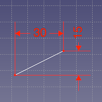
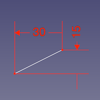
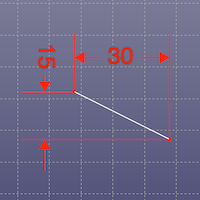
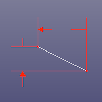
Es gibt eine weitere Einstellung, die einen Einfluss auf Skizzen hat. Ist die Einstellung Transparente Objekte auf der Registerkarte Anzeige → 3D-Viewer auf Zusätzlicher Rückseiten-Render-Durchgang gesetzt, fehlt auf einigen Systemen die Pfeilspitzen an einem Ende der Skizzenmaße. Von der Rückseite betrachtet kann auch die Maßzahl fehlen. Die Versionen 0.19 bis 0.21 (außer Link-Branch) sind betroffen. In den Versionen 0.19 und 0.20 tritt der Effekt nur dann auf, wenn Raster anzeigen im Abschnitt Erweiterte Steuerung des Lösers im Aufgaben-Bereich deaktiviert wurde, wie unten dargestellt.
Siehe Forumsbeitrag.
Vorderansicht, Raster aktiviert und Raster deaktiviert
Rückansicht, Raster aktiviert und Raster deaktiviert; die Pfeilspitzen fehlen an den gegenüberliegenden Enden und zusätzlich auch die Maßzahl
(FIXME)
- Die Werkzeuge: Skizze erstellen, Skizze bearbeiten, Skizze verlassen, Skizze anzeigen, View section, Skizze einer Fläche zuordnen..., Reorient sketch, Skizze überprüfen, Skizzen zusammenführen, Skizze spiegeln
- Skizzen-Geometrien: Punkt, Linie, Bögen erstellen, Bogen, Kreisbogen durch drei Punkte, Kreise erstellen, Kreis, Kreis durch drei Punkte, Kegelförmige Körper erstellen, Ellipse mit Mittelpunkt, Ellipse durch drei Punkte, Ellipsenbogen, Hyperbel erstellen, Parabel erstellen, B-splines erstellen, B-spline, Create periodic B-spline, Linienzug (Mehrpunktlinie), Rechteck, Reguläres Polygon erstellen, Dreieck, Quadrat, Fünfeck, Sechseck, Siebeneck, Achteck, Create Regular Polygon, Nut, Abrundung erstellen, Kante zuschneiden, Verlängern, Externe Geometrie, CarbonCopy, Konstruktionsmodus
- Skizzenbeschränkungen
- Geometrische Beschränkungen Koinzidenz erzwingen, Punkt auf Objekt festlegen, Vertikal, Horizontal, Parallel, Orthogonal, Tangente, Gleichheit, Symmetrisch, Constrain Block
- Dimensional constraints Sperren, Horizontaler Abstand, Vertikaler Abstand, Distanz festlegen, Radius festlegen, Winkel festlegen, Snell's Law, Umschalten auf steuernde Bemaßung,
- Sketcher tools Select solver DOFs, Close Shape, Connect Edges, Select Constraints, Select Origin, Select Vertical Axis, Select Horizontal Axis, Select Redundant Constraints, Select Conflicting Constraints, Select Elements Associated with constraints, Show/Hide internal geometry, Symmetry, Clone, Copy, Move, Rectangular Array, Delete All Geometry, Delete All Constraints
- Sketcher B-spline tools Show/Hide B-spline degree, Show/Hide B-spline control polygon, Show/Hide B-spline curvature comb, Show/Hide B-spline knot multiplicity, Convert Geometry to B-spline, Increase degree, Increase knot multiplicity, Decrease knot multiplicity
- Sketcher virtual space Switch Virtual Space
- Erste Schritte
- Installation: Herunterladen, Windows, Linux, Mac, Zusätzliche Komponenten, Docker, AppImage, Ubuntu Snap
- Grundlagen: Über FreeCAD, Graphische Oberfläche, Mausbedienung, Auswahlmethoden, Objektname, Voreinstellungseditor, Arbeitsbereiche, Dokumentstruktur, Objekteigenschaften, FreeCAD unterstützen, Spenden
- Hilfe: Anleitungen, Videoanleitungen
- Arbeitsbereiche: Std Base, Arch, Assembly, BIM, CAM, Draft, FEM, Inspection, Material, Mesh, OpenSCAD, Part, PartDesign, Points, Reverse Engineering, Robot, Sketcher, Spreadsheet, Surface, TechDraw, Test Framework
