Sketcher Workbench/cs

Úvod
Pomocí ![]() Pracovní plochy Sketcher Lze vytvářet 2D náčrtky určené pro použití v jiných pracovních plochách. 2D náčrtky jsou výchozím bodem pro mnoho CAD modelů. Obvykle definují profily a cesty pro operace k vytvoření 3D tvarů. Konečný tvar modelu může záviset na několika náčrtcích.
Pracovní plochy Sketcher Lze vytvářet 2D náčrtky určené pro použití v jiných pracovních plochách. 2D náčrtky jsou výchozím bodem pro mnoho CAD modelů. Obvykle definují profily a cesty pro operace k vytvoření 3D tvarů. Konečný tvar modelu může záviset na několika náčrtcích.
Spolu s booleovskými operacemi definovanými v ![]() pracovní ploše Part, tvoří Sketcher Workbench, zkráceně "Sketcher", základ metody konstruktivní geometrie těles (CSG) pro vytváření těles. Spolu s operacemi
pracovní ploše Part, tvoří Sketcher Workbench, zkráceně "Sketcher", základ metody konstruktivní geometrie těles (CSG) pro vytváření těles. Spolu s operacemi ![]() pracovní plochy PartDesign, tvoří také základ metodiky editace prvků pro vytváření těles. Ale náčrtky používá i mnoho jiných pracovních ploch.
pracovní plochy PartDesign, tvoří také základ metodiky editace prvků pro vytváření těles. Ale náčrtky používá i mnoho jiných pracovních ploch.
Pracovní plocha Sketcher obsahuje vazby, což umožňuje 2D tvarům dodržovat přesné geometrické definice z hlediska délky, úhlů a vztahů (horizontálnost, vertikálnost, kolmost atd.). Řešitel vazeb vypočítá rozsah vazeb 2D geometrie a umožňuje interaktivní prozkoumání stupňů volnosti náčrtu.
Sketcher není určen k vytváření 2D výkresů. Jakmile jsou náčrtky použity k vytvoření pevného prvku, jsou automaticky skryty a vazby jsou viditelné pouze v režimu úpravy náčrtu. Pokud potřebujete pouze vytvořit 2D pohledy pro tisk a nechcete vytvářet 3D modely, podívejte se na Pracovní plochu Draft.

Plně vázaná skica
Vazby
Vazby se používají k omezení stupňů volnosti objektu. Například přímka bez vazeb má 4 stupně volnosti (zkráceně „DoF“): lze ji posouvat vodorovně nebo svisle, lze ji natáhnout a lze ji otáčet.
Použití vodorovné nebo svislé vazby nebo vazbu úhlu (relativně k jiné přímce nebo k některé z os) omezí její možnosti otáčení, takže jí zbudou jen tři stupně volnosti. Zavazbení jednoho bodu v relaci k počátku odebere další 2 stupně volnosti. A aplikace vazby rozměru odebere poslední stupeň volnosti. Přímka je potom považována za plně zavazbenou.
Objekty lze vzájemně vázat. Dvě přímky lze spojit v jednom z jejich bodů pomocí vazby souběhu. Mezi nimi lze nastavit úhel nebo je lze nastavit jako kolmé. Přímka může být tečná k oblouku nebo kružnici atd. Náčrt může mít několik různých řešení a jeho plné zavazbení může znamenat, že na základě použitých vazeb bylo dosaženo pouze jednoho z těchto možných řešení. Viz také: Překlápění.
Existují dva druhy vazeb: geometrické a rozměrové. Jsou podrobně popsány v sekci Nástroje níže.
Úpravy vazeb
Při vytvoření řídící rozměrové vazby a pokud je vybrána předvolba Po vytvoření rozměrové vazby se zeptat na hodnotu v předvolbách (výchozí nastavení), se otevře dialogové okno pro úpravu její hodnoty.

Můžete zadat číselnou hodnotu nebo výraz a je možné vazbu pojmenovat, aby se usnadnilo jeho použití v jiných výrazech. Můžete také zaškrtnout políčko Reference, aby se vazba přepnula do referenčního režimu.
Chcete-li upravit hodnotu existující rozměrové vazby, proveďte jednu z následujících akcí:
- Poklepejte na hodnotu vazby ve 3D pohledu.
- Poklepejte na vazbu v dialogovém okně sketcheru.
- Klikněte pravým tlačítkem myši na vazbu v dialogovém okně Sketcheru a z kontextového menu vyberte možnost Upravit hodnotu.
Přesunutí vazeb
Dimenzionální vazbu lze ve 3D zobrazení přemístit tažením. Podržte levé tlačítko myši nad hodnotou vazby a pohybujte myší. Symboly geometrických vazeb jsou umístěny automaticky a nelze je přesouvat.
Náčrtky profilů
Při vytváření náčrtu, který lze použít jako profil pro generování těles, je třeba dodržovat určitá pravidla:
- Náčrt musí obsahovat pouze uzavřené kontury. Mezery mezi koncovými body, jakkoli malé, nejsou povoleny.
- Obrysy mohou být vnořené, aby vytvářely dutiny, ale neměly by se protínat samy se sebou ani s jinými obrysy.
- Obrysy nemohou sdílet hrany s jinými obrysy. Duplicitní nebo překrývající se hrany nejsou povoleny.
- T-spojení, tj. více než dvě hrany sdílející společný bod nebo bod dotýkající se hrany, nejsou povolena.

Neplatné náčrtky:
1. Otevřený obrys (volné koncové body zvýrazněné nástrojem Ověřit náčrt)
2. Protínající se obrysy
3. Duplicitní hrany (koncové body překrývajících se hran zvýrazněné nástrojem Ověřit náčrt)
4. T-spoje
Tato pravidla se nevztahují na konstrukční geometrii (výchozí barva modrá), která se nezobrazuje mimo režim úprav nebo pokud je náčrt použit pro jiný účel. V závislosti na pracovním prostředí a nástroji, který bude profilový náčrt používat, mohou platit další omezení.
Internal faces
If the ÚdajeMake Internals property of a sketch is set to true internal faces are generated based on the edges in the sketch. These faces can be selected as closed profiles for operations. Intersecting contours and T-connections are allowed, they just result in additional faces.

Nástroje
Nástroje pracovní plochy Sketcher se nacházejí v menu Sketch a/nebo v několika panelech nástrojů. Téměř všechny panely nástrojů Sketcheru se zobrazují pouze v režimu úpravy skici. Jedinou výjimkou je panel nástrojů Sketcheru, který se zobrazuje pouze v případě, že žádná skica není v režimu úpravy.
Některé nástroje jsou také k dispozici v kontextovém menu 3D pohledu, když je skica v režimu úprav, nebo v kontextových menu dialogového okna Sketcher.
Pokud je skica v režimu úprav, panel nástrojů Struktura je skrytý, protože žádný z jeho nástrojů nelze použít.
Obecné
Panel nástrojů sketcheru
 Nový náčrt: Vytvoří nový náčrt a otevře dialogové okno Dialogu sketcheru pro jeho úpravu.
 Upravit náčrt: Otevře dialogové okno Sketcheru pro úpravu existujícího náčrtu.
 Připojit náčrt: Připojí náčrt k vybrané geometrii.
 Přeorientovat náčrt: Umístí náčrt na jednu z hlavních rovin s volitelným odsazením. Lze také použít k oddělení náčrtu.
 Ověřit náčrt: Umí analyzovat a opravit náčrt, který již nelze upravovat nebo má neplatné vazby nebo přidat chybějící shodné vazby.
 Sloučit náčrtky: Sloučí dva nebo více náčrtků.
 Zrcadlení náčrtu: Zrcadlí náčrty podle osy X, osy Y nebo počátku.
Nástrojová lišta režimu úprav
 Opustit náčrt: Ukončí režim úprav náčrtu a zavře dialogové okno Sketcher.
 Cancel Editing: Leaves sketch edit mode, reverts any changes, and closes the Sketcher Dialog. introduced in 26.3
 Zarovnat pohled ke skice: Zarovná 3D pohled ke skice.
 Přepnout zobrazení sekce: Přepne dočasnou rovinu sekce, která skryje všechny objekty a části objektů před rovinou náčrtu.
Ostatní
 Zastavit operaci: Zastaví všechny aktuálně spuštěné nástroje pro tvorbu geometrie nebo vazeb.
- Mřížka: Nastavení mřížky lze změnit v menu sekce Sketch Edit dialogového okna Sketcher.
- Zachycení: Nastavení zachycení lze změnit ve stejném menu.
- Pořadí vykreslování: Pořadí vykreslování lze změnit ve stejném menu.
Geometrie
Jedná se o nástroje pro vytváření objektů.
 Bod: Vytvoří bod.
 Lomená čára: Vytvoří sérii úseček a oblouků spojených jejich koncovými body. Nástroj má několik režimů.
 Úsečka: Vytvoří přímku. introduced in 1.0: Nástroj má tři režimy.

 Vytvořit oblouk:
- Oblouk ze středu: Vytvoří oblouk podle jeho středu a koncových bodů. introduced in 1.0: Nebo z jeho koncových bodů a bodu podél oblouku.
 Oblouk ze 3 bodů: Vytvoří oblouk z jeho koncových bodů a bodu podél oblouku. introduced in 1.0: Jedná se o stejný nástroj jako Oblouk ze středu, ale s odlišným počátečním režimem.
 Eliptický oblouk: Vytvoří eliptický oblouk.
 Hyperbolický oblouk: Vytvoří hyperbolický oblouk.
 Parabolický oblouk: Vytvoří parabolický oblouk.
 Vytvořit kruh/elipsu:
- Kruh ze středu: Vytvoří kruh podle jeho středu a bodu na kružnici. introduced in 1.0: Nebo ze tří bodů podél kružnice.
 Kruh ze 3 bodů: Vytvoří kruh ze tří bodů ležících na kružnici. introduced in 1.0: Jedná se o stejný nástroj jako Kruh ze středu, ale s odlišným počátečním režimem.
 Elipsa ze středu: Vytvoří elipsu od jejího středu, koncového bodu jedné z jejích os a bodu podél elipsy. introduced in 1.0: Nebo z obou konců jedné z jejích os a bodu na elipse.
 Elipsa ze 3 bodů: Vytvoří elipsu z koncových bodů jedné z jejích os a bodu ležícího na elipse. introduced in 1.0: Jedná se o stejný nástroj jako Ellipsa podle středu, ale s odlišným počátečním režimem.
 Vytvořit obdélník:
- Obdélník: Vytvoří obdélník. introduced in 1.0: Nástroj má čtyři režimy. Zaoblené rohy a vytvoření odsazené kopie jsou volitelné funkce.
 Vycentrovaný obdélník: Vytvoří vycentrovaný obdélník. introduced in 1.0: Jedná se o stejný nástroj jako Obdélník, ale s odlišným počátečním režimem.
 Zaoblený obdélník: Vytvoří zaoblený obdélník. Idem.
 Vytvořit mnohoúhelník:
 Trojúhelník: vytvoří rovnostranný trojúhelník. introduced in 1.0: Jedná se o stejný nástroj jako Mnohoúhelník, ale s přednastaveným počtem stran na konkrétní hodnotu.
 Čtverec: Vytvoří čtverec. Idem.
 Pětiúhelník: Vytvoří pětiúhelník. Idem.
- Šestiúhelník: Vytvoří šestiúhelník. Idem.
 Sedmiúhelník: Vytvoří sedmiúhelník. Idem.
 Osmiúhelník: Vytvoří osmiúhelník. Idem.
 Mnohoúhelník: Vytvoří pravidelný mnohoúhelník. Lze zadat počet stran.
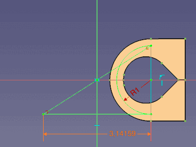
 Vytvořit drážku:
- Drážka: Vytvoří drážku.
 Oblouková drážka: Vytvoří obloukovou drážku. introduced in 1.0
 Vytvořit B-Splajn:
- B-Splajn: Vytvoří křivku B-spline z kontrolních bodů. introduced in 1.0: Nebo z uzlových bodů.
 Periodická B-spline: Vytvoří periodickou (uzavřenou) B-spline křivku z kontrolních bodů. introduced in 1.0: Jedná se o stejný nástroj jako B-Spline, ale s odlišným počátečním režimem.
 B-spline z uzlů: Vytvoří křivku B-spline z uzlových bodů. Idem.
 Periodická B-spline z uzlů: Vytvoří periodickou (uzavřenou) B-spline křivku z uzlových bodů. Idem.
 Text: Creates text geometry controlled by a text constraint introduced in 26.3.
 Přepnout konstrukční geometrii: Přepne nástroje pro vytváření geometrie do/z konstrukčního režimu nebo přepne vybranou geometrii do/z konstrukční geometrie.
Vazby
Jedná se o nástroje pro vytváření vazeb. Některé vazby vyžadují použití pomocných vazeb.
 Rozměrové vazby:
- Rozměr: Jedná se o nástroj pro kontextové vazby v pracovním prostředí Sketcher. Na základě aktuálního výběru nabízí vhodné rozměrové vazby, ale také geometrické vazby. introduced in 1.0
 Horizontální rozměr: Určuje horizontální vzdálenost mezi dvěma body nebo koncovými body přímky. Pokud je předem vybrán jeden bod, vzdálenost se vztahuje k počátku náčrtu.
 Vertikální rozměr: Určuje vertikální vzdálenost mezi dvěma body nebo koncovými body přímky. Pokud je předem vybrán jeden bod, vzdálenost se vztahuje k počátku náčrtu.
 Vzdálenost: Určuje délku přímky, vzdálenost mezi dvěma body, kolmou vzdálenost mezi bodem a přímkou; nebo vzdálenost mezi okraji dvou kruhů nebo oblouků, nebo mezi okrajem kruhu nebo oblouku a přímkou; nebo introduced in 1.0, délku oblouku.
 Rozměr poloměru/průměru: Upravuje poloměr oblouků a kruhů váhy B-spline a průměr kruhů.
 Rozměr poloměru: Určuje poloměr kruhů, oblouků a kruhů s váhou B-spline.
 Rozměr průměru: Určuje průměr kruhů a oblouků.
 Rozměr úhlu: Určuje úhel mezi dvěma hranami, úhel přímky s vodorovnou osou náčrtu nebo úhel otevření kruhového oblouku.
 Zamknout polohu: Použije vazbu horizontální rozměr a vertikální rozměr na body. Pokud je vybrán jeden bod, omezení odkazují na počátek náčrtu. Pokud jsou vybrány dva nebo více bodů, omezení odkazují na poslední bod ve výběru.
 Vazba totožnosti (sjednocení): Vytvoří souběžnou vazbu mezi body, zafixuje body na hranách nebo osách nebo vytvoří soustřednou vazbu. Kombinuje nástroje Vazbu souběžnosti a Vazbu bodu na objektu. introduced in 1.0
 Souběžná vazba: Vytvoří souběžnou vazbu mezi body nebo soustřednou vazbu.
 Vazba bodu na objekt: Upravuje body na hranách nebo osách.
 Horizontální/vertikální vazba:
- Horizontální/vertikální vazba: Váže přímky nebo dvojice bodů tak, aby byly vodorovné nebo svislé, podle toho, co je blíže aktuálnímu zarovnání. Kombinuje nástroje Horizontální vazba a Vertikální vazba. introduced in 1.0
 Horizontální vazba: Vazba zajišťuje, že přímky nebo dvojice bodů jsou horizontální.
 Vertikální vazba: Vazba zajišťuje, že přímky nebo dvojice bodů jsou vertikální.
 Vazba rovnoběžnosti: Vynutí, aby byly linie rovnoběžné.
 Vazba kolmosti: Zajišťuje, aby dvě přímky byly kolmé, nebo aby dvě hrany, nebo hrana a osa, byly kolmé v místě jejich průsečíku. Vazba může také spojit dvě hrany a vynutit jejich kolmost v místě spoje.
 Vazba tečny/kolineární: Zaručí, že dvě hrany nebo hrana a osa budou tečné. Vazba může také spojit dvě hrany a vynutit jejich tečnost ve spoji. Pokud jsou vybrány dvě přímky, budou kolineární.
 Vazba shodnosti: Zajišťuje, aby hrany měly stejnou délku ( přímky) nebo zakřivení (ostatní hrany kromě B-spline).
 Vazba symetrie: Zajišťuje symetrii dvou bodů vzhledem k přímce nebo ose, případně vzhledem k třetímu bodu.
 Vazba blokace: Blokuje hrany na místě pomocí jediného omezení. Je určeno především pro B-splajny.
 Group Constraint: Groups selected geometry. introduced in 26.3
 Vazba refrakce: Zajišťuje, aby dvě přímky dodržovaly zákon lomu světla při průchodu rozhraním.
 Přepnutí vazeb:
- Přepínání řídící/referenčních vazby: Přepíná nástroje pro vytváření rozměrových vazeb mezi režimem řízení a referenčním režimem nebo přepíná vybrané rozměrové vazby mezi těmito režimy.
 Přepínání vazeb: Aktivuje nebo deaktivuje vybrané vazby.
Nástroje Sketcheru
 Vytvořit zaoblení/zkosení:
- Zaoblení: Vytvoří zaoblení mezi dvěma neparalelními hranami. introduced in 1.0: Tento nástroj může také vytvářet zkosení.
 Zkosení: vytvoří zkosení mezi dvěma neparalelními hranami. Jedná se o stejný nástroj jako Zaoblení, ale s odlišným počátečním režimem. introduced in 1.0
 Upravit hranu:
- Oříznout hranu: Ořízne hranu v nejbližších průsečících s jinými hranami.
 Rozdělit hranu: Rozdělí hranu a přenese většinu vazeb.
 Prodloužit hranu: Prodlouží nebo zkrátí přímku nebo oblouk na libovolné místo nebo na cílovou hranu či bod.
 Externí geometrie:
- Externí projekce: Vytvoří hrany projekce vnější geometrie. introduced in 1.1
 Externí průsečík: Vytvoří průsečíky hran vnější geometrie s rovinou náčrtu. introduced in 1.1
 Karbonová kopie: Zkopíruje veškerou geometrii a vazby z jiného náčrtu do aktivního náčrtu.
 Vybrat počátek: Vybere počátek náčrtu.
 Vybrat horizontální osu: Vybere horizontální osu náčrtu.
 Vybrat vertikální osu: Vybere vertikální osu náčrtu.
 Přesun/transformace pole: Přesouvá nebo volitelně vytváří kopie vybraných prvků. introduced in 1.0
 Rotace/Polarní transformace: Otáčí nebo volitelně vytváří otočené kopie vybraných prvků. introduced in 1.0
 Měřítko: Změní měřítko nebo volitelně vytvoří kopie vybraných prvků v měřítku. introduced in 1.0
 Odsazení: Vytvoří rovnoměrně vzdálené hrany kolem vybraných hran. introduced in 1.0
 Zrcadlení: Vytvoří zrcadlené kopie vybraných prvků.
 Odstranit vyrovnání os: Odstraní zarovnání os vybraných hran nahrazením horizontálních a vertikálních vazeb paralelními a kolmými vazbami.
 Odstranit veškerou geometrii: Odstraní veškerou geometrii a všechny vazby ze skici.
 Odebrat všechny vazby: Odebere všechny vazby ze skici.
 Kopírování prvků: Viz Kopírování, vyjmutí a vložení.
 Vyjmutí prvků: Viz Kopírování, vyjmutí a vložení.
 Vložení prvků: Viz Kopírování, vyjmutí a vložení.
Nástroje B-Spline
 Geometrie do B-spline: Převádí hrany na B-splajny.
 Zvýšit stupeň B-spline: Zvyšuje stupeň (řád) B-spline.
 Snížení stupně B-spline: Snižuje stupeň (řád) B-spline.
 Zvýšení multiplicity uzlů: Zvyšuje multiplicitu uzlu B-spline.
 Snížení multiplicity uzlů: Snižuje multiplicitu uzlu B-spline.
 Vložit uzel: Vloží uzel do B-spline nebo zvýší multiplicitu existujícího uzlu.
 Připojit křivky: Vytvoří B-spline spojením dvou existujících B-spline nebo jiných hran.
Vizuální pomůcky
 Výběr nedostatečně vázaných prvků: Vybere prvky ve skici, které nejsou plně vázány.
 Vybrat související vazby: Vybere vazby spojené s prvky náčrtu.
 Vybrat přidruženou geometrii: Vybere prvky náčrtu spojené s vazbami.
 Vybrat nadbytečné vazby: Vybere nadbytečné vazby ve skice.
 Vybrat konfliktní vazby: Vybere konfliktní vazby ve skici.
 Přepnout kružnicový pomocník pro oblouky: Zobrazí nebo skryje kruhové pomocné prvky (podkladové virtuální kruhy) pro oblouky ve všech skicách. introduced in 1.0
 Přepnout informační vrstvu B-Spline:
 Přepnout stupeň B-spline: Zobrazí nebo skryje stupeň B-spline ve všech skicách.
- Přepínání ovládacího polygonu B-spline: Zobrazí nebo skryje ovládací polygon B-spline ve všech skicách.
 Přepnout hřeben zakřivení B-spline: Zobrazí nebo skryje hřeben zakřivení B-spline ve všech skicách.
 Přepnout multiplicitu uzlu B-spline: Zobrazí nebo skryje multiplicitu uzlů B-spline ve všech skicách.
 Přepnout váhu kontrolního bodu B-spline: Zobrazí nebo skryje váhu kontrolního bodu B-spline ve všech skicách.
 Přepnout vnitřní geometrii: Odstraní vnitřní geometrii prvků nebo znovu vytvoří chybějící vnitřní geometrii.
 Přepnout virtuální prostor: (od)skryje vazby nebo přepne viditelný virtuální prostor.
Zastaralé nástroje
 Klonování: Klonuje prvek skicáře. Není k dispozici v 1.0 and above.
 Uzavřít tvar: Vytvoří uzavřený tvar pomocí vazby shody koncových bodů. Není k dispozici v 0.21 and above.
 Zaoblení se zachováním rohu: Vytvoří zaoblení mezi dvěma neparalelními přímkami při zachování jejich rohového bodu. Není k dispozici v 1.0 and above.
 Spojit hrany: Propojí prvky Sketcheru pomocí vazby shody na koncových bodech. Není k dispozici v 0.21 and above.
 Kopírovat: Zkopíruje prvek Sketcheru. Není k dispozici v 1.0 and above.
 Externí geometrie: Promítá hrany a/nebo vrcholy patřící k objektům mimo náčrt na rovinu náčrtu. Není k dispozici v 1.1 and above.
 Přesunout: Přesune vybranou geometrii s ohledem na poslední vybraný bod. Není k dispozici v 1.0 and above.
 Obdélníkové pole: Vytvoří pole vybraných prvků Sketcheru. Není k dispozici v 1.0 and above.
Předvolby
 Předvolby: Předvolby pro pracovní plochu Sketcher.
Pomůcky pro kreslení
Pracovní plocha Sketcher obsahuje několik pomůcek pro kreslení a dalších funkcí, které mohou pomoci při vytváření geometrie a aplikování vazeb.
Režimy pokračování
Existují dva režimy pokračování: Režim pokračování při vytváření geometrie a Režim pokračování při vytváření vazeb. Pokud jsou tyto možnosti zaškrtnuty (výchozí nastavení) v předvolbách, související nástroje se po dokončení restartují. Pro opuštění kontinuálního nástroje stiskněte klávesu Esc nebo pravé tlačítko myši. Toto je nutné opakovat, pokud již byl zadán nástroj s kontinuální geometrií. Kontinuální nástroj můžete také ukončit spuštěním jiného nástroje pro vytváření geometrie nebo vazby. Všimněte si, že stisknutím klávesy Esc, pokud není aktivní žádný nástroj, opustíte režim úpravy náčrtu. Pokud často nechtěně stisknete klávesu Esc, zrušte v předvolbách zaškrtnutí políčka Klávesa Esc může opustit režim úprav náčrtu.
Automatické vazby
Ve skicách, u kterých je zaškrtnuto políčko Automatické vazby (výchozí nastavení), se automaticky použije několik vazeb. Ikona navrhovaného automatické vazby se zobrazí vedle kurzoru, pokud je správně umístěn. Kliknutím levým tlačítkem myši se pak tato vazba použije. Jedná se o nastavení pro jednotlivé skici, které lze změnit v dialogovém okně Sketcher nebo změnou vlastnosti PohledAutoconstraints property skici.
Automaticky se uplatňují následující vazby:
- Shoda
- Bod na objektu
- Horizontální
- Vertikální
- Tečna
- introduced in 1.0: Symetrie (střed linie)
Přichytávání
Je možné přichytit se k liniím a průsečíkům mřížky a přichytit se k hranám geometrie a středům linií a oblouků a k určitým úhlům. Upozorňujeme, že přichycení samo o sobě nevytváří vazby. Například pouze pokud je zapnuta funkce Automatické vazby, vytvoří přichycení k hraně vazbu bod na objektu. Ale pouhé vybrání bodu na okraji by pak mělo stejný výsledek.
Parametry zobrazení
V závislosti na vybrané možnosti v preferencích lze povolit pouze rozměrové parametry zobrazení nebo rozměrové i poziční parametry zobrazení. Poziční parametry umožňují zadání přesných souřadnic, například středu kruhu nebo počátečního bodu přímky. Rozměrové parametry umožňují zadání přesných rozměrů, například poloměru kruhu nebo délky a úhlu přímky. Parametry zobrazené na obrazovce nejsou k dispozici pro všechny nástroje.

Určení středového bodu kruhu s povolenými pozičními parametry

Určení poloměru kruhu s povolenými dimenzionálními parametry
Pokud jsou hodnoty zadány a potvrzeny stisknutím klávesy Enter nebo Tab, přidají se automaticky související vazby. Pokud jsou zobrazeny dva parametry současně, například souřadnice X a Y bodu, je možné zadat jednu hodnotu a vybrat bod, který definuje druhou hodnotu. V závislosti na objektu mohou být pro jeho úplné zavazbení zapotřebí další vazby. Vazby vyplývajících z parametrů zobrazení mají přednost před vazbami, které mohou vyplývat z automatických vazeb.

Oblouk vytvořený zadáním všech parametrů zobrazení s automaticky vytvořenými vazbami
Zobrazení souřadnic
Pokud je v předvolbách zaškrtnuto políčko Zobrazit souřadnice vedle kurzoru při úpravách (výchozí nastavení), zobrazí se vedle kurzoru parametry aktuálního geometrického nástroje (souřadnice, poloměr nebo délka a úhel). Tato funkce je deaktivována, když jsou zobrazeny parametry zobrazení.
Metody výběru
V režimu úpravy náčrtu lze použít následující metody výběru:
Výběr prvků ve 3D pohledu
Stejně jako jinde ve FreeCADu lze prvek ve 3D pohledu vybrat jediným kliknutím levým tlačítkem myši. Při výběru více prvků však není nutné držet stisknutou klávesu Ctrl. Podržení této klávesy je však možné a má tu výhodu, že můžete kliknout mimo, aniž byste ztratili výběr. Tímto způsobem lze vybrat hrany, body a vazby.
Výběr rámečkem ve 3D pohledu
Výběr rámečku ve 3D pohledu funguje bez použití Std BoxSelection nebo Std BoxElementSelection:
- Ujistěte se, že není aktivní žádný nástroj.
- Proveďte jednu z následujících akcí:
- Klikněte na prázdnou oblast a přetáhněte obdélník zleva doprava, abyste vybrali prvky, které leží zcela uvnitř obdélníku.
- Klikněte na prázdnou oblast a přetáhněte obdélník zprava doleva, abyste vybrali také prvky, které se dotýkají nebo protínají obdélník.
Pomocí rámečku můžete vybrat hrany a body, nelze však vybrat vazby.
Výběr propojené geometrie ve 3D pohledu
Poklepáním na hranu v 3D pohledu vyberete všechny hrany přímo a nepřímo spojené s touto hranou prostřednictvím koncových bodů. Není nutné, aby hrany byly spojeny souběžnými vazbami, koncové body musí mít pouze stejné souřadnice.
Dialogové okno výběru Sketcheru
Hrany a body lze také vybrat v sekci Prvky dialogového okna Sketcheru a vazby v sekci Vazby tohoto dialogového okna.
Klávesová zkratka Vybrat vše
Chcete-li vybrat vše ve skice, použijte standardní klávesovou zkratku Ctrl+A nebo možnost Úpravy→ Vybrat vše z menu.
Kopírování, vyjmutí a vložení
Standardní klávesové zkratky Ctrl+C, Ctrl+X a Ctrl+V lze použít ke kopírování, vyjmutí a vložení vybrané geometrie Sketcheru včetně souvisejících vazeb. Tyto nástroje jsou však k dispozici také v menu Sketch → Nástroje náčrtu. Lze je použít v rámci stejného náčrtu, ale také mezi různými náčrtky nebo samostatnými instancemi FreeCADu. Jelikož jsou data zkopírována do schránky ve formě kódu Pythonu, lze je použít i jinými způsoby (např. sdílet na fóru).
Osvědčené postupy
Každý uživatel CADu si postupem času vyvine svůj vlastní způsob práce, ale existuje několik užitečných obecných zásad, které je dobré dodržovat.
- Série jednoduchých náčrtů se snadněji spravuje než jeden složitý náčrt. Například první náčrt může být vytvořen pro základní 3D prvek (například podložku nebo rotaci), zatímco druhý může obsahovat otvory nebo výřezy (kapsy). Některé detaily lze vynechat a realizovat je později jako 3D prvky. Pokud je ve skice příliš mnoho zaoblení, můžete se rozhodnout je vynechat a přidat je jako 3D prvek.
- Vždy vytvářejte uzavřený profil, jinak váš náčrt nevytvoří těleso, ale sadu otevřených ploch. Pokud nechcete, aby některé objekty byly zahrnuty do vytvoření tělesa, přepněte je na konstrukční prvky pomocí nástroje Přepnout konstrukční geometrii.
- Pomocí funkce Automatické vazby můžete omezit počet vazeb, které budete muset přidat manuálně.
- Obecně platí, že nejprve použijte geometrická omezení, poté rozměrová omezení a nakonec uzamkněte náčrt. Ale pamatujte: pravidla jsou od toho, aby se porušovala. Pokud máte potíže s manipulací s náčrtem, může být užitečné nejprve provést vazby několika objektů a teprve poté profil dokončit.
- Pokud je to možné, vycentrujte náčrt na počátek (0,0). Pokud náčrt není symetrický, umístěte jeden z jeho bodů na počátek.
- Pokud máte možnost volby mezi rozměrem vzdálenosti a horizontálním nebo vertikálním rozměrem, upřednostněte ten druhý. Horizontální a vertikální rozměry jsou výpočetně levnější.
- Obecně platí, že nejvhodnějšími vazbami jsou: vodorovné a svislé vazby; vodorovné a svislé rozměry; tečné vazby mezi body. Pokud je to možné, omezte použití těchto vazeb: dimenze vzdálenosti; tečná vazba mezi hranami; vazba bodu na objekt; symetrická vazba.
- Pokud máte pochybnosti o platnosti náčrtu po jeho dokončení (prvky se zbarví zeleně), zavřete dialogové okno Sketcheru a použijte Ověřit Sketch.
Překlopení
Jev, kdy plně zavazbený náčrt, obvykle po významné změně jedné z jeho dimenzí, dosáhne nezamýšleného nového stavu, se nazývá "překlopení". V následujícím příkladu změna jednoho rozměru zcela mění tvar náčrtu. Všimněte si, že náčrt s novým tvarem je stále plně zavazben.


Původní náčrt (vlevo) a stejný náčrt po zvýšení hodnoty 20 mm na 1000 mm (vpravo)
Metody ke snížení překlápění
Měňte rozměry po malých krocích
To není vždy praktické, ale změna hodnot rozměrů po menších krocích může fungovat.
Použijte jiný řešič
Řešitel LevenbergMarquardt, který není výchozím řešitelem, je známý tím, že je méně náchylný k překlápění. Více informací najdete v dialogovém okně Sketcheru.
Použijte horizontální a vertikální rozměry

Použití horizontálních a vertikálních rozměrů namísto rozměrů vzdálenosti nebo vazeb rovnosti může zabránit převrácení. Body zavazbené těmito rozměry vymění místa pouze v případě, že se změní znaménko jejich hodnoty. Na obrázku výše jsou přidané (oranžové) rozměrové vazby propojeny s původními rozměry pomocí výrazů.
Použijte úhlové rozměry

Místo horizontální a vertikální vazby lze použít také úhlové rozměry. Úhel mezi hranami vázaný rozměry úhlů se nezmění. 180° se nestane 0°, 90° se nestane 270° atd. Na obrázku byly nahrazeny všechny vodorovné a svislé vazby, ale již nahrazení dvou z nich je v tomto případě účinné.
Návody
- Lekce Sketcheru od chrisb. Jedná se o více než 80stránkový dokument ve formátu PDF, který slouží jako podrobný manuál k programu Sketcher. Vysvětluje základy používání programu Sketcher a podrobně popisuje vytváření geometrických tvarů a jednotlivých omezení.
- Základní návod pro Sketcher pro začátečníky
- Sketcher Micro Tutorial – Praktické použití vazeb
- Požadavky na náčrt Minimální požadavky na náčrt a kompletní určení náčrtu
Skriptování
Stránka Sketcher skriptování obsahuje příklady toho, jak vytvářet vazby pomocí skriptů v jazyce Python.
Příklady
Několik nápadů, co lze pomocí nástrojů Sketcheru vytvořit, najdete na stránce Příklady Sketcheru.
- General: New Sketch, Edit Sketch, Attach Sketch, Reorient Sketch, Validate Sketch, Merge Sketches, Mirror Sketch, Leave Sketch, Align View to Sketch, Toggle Section View, Stop Operation, Grid, Snap, Rendering Order
- Geometries: Point, Polyline, Line, Arc From Center, Arc From 3 Points, Elliptical Arc, Hyperbolic Arc, Parabolic Arc, Circle From Center, Circle From 3 Points, Ellipse From Center, Ellipse From 3 Points, Rectangle, Centered Rectangle, Rounded Rectangle, Triangle, Square, Pentagon, Hexagon, Heptagon, Octagon, Polygon, Slot, Arc Slot, B-Spline, Periodic B-Spline, B-Spline From Knots, Periodic B-Spline From Knots, Toggle Construction Geometry
- Constraints:
- Dimensional Constraints: Dimension, Horizontal Dimension, Vertical Dimension, Distance Dimension, Radius/Diameter Dimension, Radius Dimension, Diameter Dimension, Angle Dimension, Lock Position
- Geometric Constraints: Coincident Constraint (Unified), Coincident Constraint, Point-On-Object Constraint, Horizontal/Vertical Constraint, Horizontal Constraint, Vertical Constraint, Parallel Constraint, Perpendicular Constraint, Tangent/Collinear Constraint, Equal Constraint, Symmetric Constraint, Block Constraint, Refraction Constraint
- Constraint Tools: Toggle Driving/Reference Constraints, Toggle Constraints
- Sketcher Tools: Fillet, Chamfer, Trim Edge, Split Edge, Extend Edge, External Projection, External Intersection, Carbon Copy, Select Origin, Select Horizontal Axis, Select Vertical Axis, Move/Array Transform, Rotate/Polar Transform, Scale, Offset, Mirror, Remove Axes Alignment, Delete All Geometry, Delete All Constraints, Copy Elements, Cut Elements, Paste Elements
- B-Spline Tools: Geometry to B-Spline, Increase B-Spline Degree, Decrease B-Spline Degree, Increase Knot Multiplicity, Decrease Knot Multiplicity, Insert Knot, Join Curves
- Visual Helpers: Select Under-Constrained Elements, Select Associated Constraints, Select Associated Geometry, Select Redundant Constraints, Select Conflicting Constraints, Toggle Circular Helper for Arcs, Toggle B-Spline Degree, Toggle B-Spline Control Polygon, Toggle B-Spline Curvature Comb, Toggle B-Spline Knot Multiplicity, Toggle B-Spline Control Point Weight, Toggle Internal Geometry, Switch Virtual Space
- Additional: Sketcher Dialog, Preferences, Sketcher scripting
- Getting started
- Installation: Download, Windows, Linux, Mac, Additional components, Docker, AppImage, Ubuntu Snap
- Basics: About FreeCAD, Interface, Mouse navigation, Selection methods, Object name, Preferences, Workbenches, Document structure, Properties, Help FreeCAD, Donate
- Help: Tutorials, Video tutorials
- Workbenches: Std Base, Assembly, BIM, CAM, Draft, FEM, Inspection, Material, Mesh, OpenSCAD, Part, PartDesign, Points, Reverse Engineering, Robot, Sketcher, Spreadsheet, Surface, TechDraw, Test Framework
- Hubs: User hub, Power users hub, Developer hub