PartDesign Workbench/fi

Introduction
The ![]() PartDesign Workbench provides tools for modeling solid components. It is mostly focused on creating mechanical components that can be manufactured and assembled into a finished product. Nevertheless, the created solids can be used for any other purpose such as BIM modeling, finite element analysis, or machining and 3D printing.
PartDesign Workbench provides tools for modeling solid components. It is mostly focused on creating mechanical components that can be manufactured and assembled into a finished product. Nevertheless, the created solids can be used for any other purpose such as BIM modeling, finite element analysis, or machining and 3D printing.
The PartDesign Workbench uses a feature based methodology. A component is represented by the Body object container. The Body defines a local coordinate system and contains the cumulative features that define the component. Most features are based on parametric sketches and are either additive or subtractive. For example, the Pad tool adds the extruded sketch to the developing solid, the Pocket tool subtracts the extruded sketch. Each feature is cumulative and builds on the result of preceding features. It is also possible to use primitives (Cylinder, Sphere, etc.) as well as solids created outside the Body as features.
See the feature editing page for a more complete explanation of this process, and then see Creating a simple component with PartDesign to get started with creating solids.
The ![]() Part Workbench provides an alternative constructive solid geometry (CSG) methodology for building shapes. For a detailed discussion of the Part Workbench versus the PartDesign Workbench see Part and Part Design.
Part Workbench provides an alternative constructive solid geometry (CSG) methodology for building shapes. For a detailed discussion of the Part Workbench versus the PartDesign Workbench see Part and Part Design.

Tools
The Part Design tools are all located in the Part Design menu and the PartDesign toolbars that appear when you load the PartDesign Workbench.
Part Design Helper Features toolbar

 New Sketch:
- New Sketch: creates a new sketch on a selected face or plane. If no face is selected while this tool is executed, the user is prompted to select a plane from the Tasks panel. The interface then switches to the Sketcher Workbench in sketch editing mode.
 Attach Sketch: attaches a sketch to geometry selected from the active body.
 Edit Sketch: opens the selected sketch for editing.
 Validate Sketch: verifies the tolerance of different points and adjusts them.
 Check Geometry: Checks the geometry of selected objects for errors.
 Sub-Shape Binder: creates a shape binder referencing geometry from one or more parent objects.
 Clone: creates a clone of the selected body.
Part Design Modeling Features toolbar
Additive tools
These are tools for creating base features or adding material to an existing body.
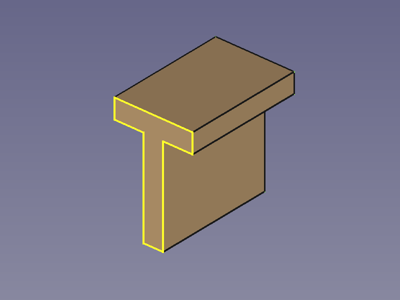
 Pad: extrudes a solid from a selected sketch.
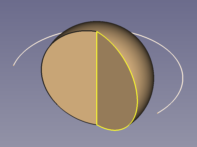
 Revolution: creates a solid by revolving a sketch around an axis. The sketch must form a closed profile.
 Additive Loft: creates a solid by making a transition between two or more sketches.
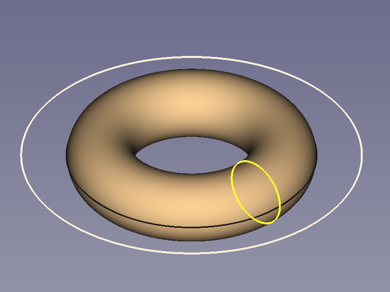
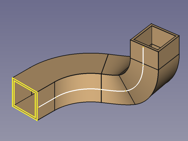
 Additive Pipe: creates a solid by sweeping one or more sketches along an open or closed path.
 Additive Helix: creates a solid by sweeping a sketch along a helix.
 Additive Primitive:
- Additive Box: creates an additive box.
 Additive Cylinder: creates an additive cylinder.
 Additive Sphere: creates an additive sphere.
 Additive Cone: creates an additive cone.
 Additive Ellipsoid: creates an additive ellipsoid.
 Additive Torus: creates an additive torus.
 Additive Prism: creates an additive prism.
 Additive Wedge: creates an additive wedge.
Subtractive tools
These are tools for subtracting material from an existing body.
 Pocket: creates a pocket from a selected sketch.
 Hole: creates a hole feature from a selected sketch. The sketch must contain one or multiple circles.
 Groove: creates a groove by revolving a sketch around an axis.
 Subtractive Loft: creates a solid shape by making a transition between two or more sketches and subtracts it from the active body.
 Subtractive Pipe: creates a solid shape by sweeping one or more sketches along an open or closed path and subtracts it from the active body.
 Subtractive Helix: creates a solid shape by sweeping a sketch along a helix and subtracts it from the active body.
 Subtractive Primitive:
- Subtractive Box: adds a subtractive box to the active body.
 Subtractive Cylinder: adds a subtractive cylinder to the active body.
 Subtractive Sphere: adds a subtractive sphere to the active body.
 Subtractive Cone: adds a subtractive cone to the active body.
 Subtractive Ellipsoid: adds a subtractive ellipsoid to the active body.
 Subtractive Torus: adds a subtractive torus to the active body.
 Subtractive Prism: adds a subtractive prism to the active body.
 Subtractive Wedge: adds a subtractive wedge to the active body.
Boolean
 Boolean Operation: imports one or more Bodies or PartDesign Clones into the active body and applies a Boolean operation.
Part Design Dress-Up Features toolbar
These tools apply a treatment to edges or faces.
 Fillet: fillets (rounds) edges of the active body.
 Chamfer: chamfers edges of the active body.
 Draft: applies an angular draft to selected faces of the active body.
 Thickness: creates a thick shell from the active body and opens selected face.
Part Design Transformation Features toolbar
These are tools for transforming existing features.
 Mirror: mirrors one or more features.
 Linear Pattern: creates a linear pattern of one or more features.
 Polar Pattern: creates a polar pattern of one or more features.
 Multi-Transform: creates a pattern by combining any of the transformations mentioned above, as well as the Scale transformation.
 Scale: scales one or more features. This is not available as a separate transformation tool.
Additional tools
Some additional tools available in the Part Design menu:
 Shape Binder: creates a shape binder referencing geometry from a single parent object.
 Involute Gear: creates an involute gear profile that can be padded.
 Sprocket: creates a sprocket profile that can be padded.
 Shaft Design Wizard: Generates a shaft from a table of values and allows to analyze forces and moments. The shaft is made with a revolved sketch that can be edited.
- Suppressed: checkbox to disable a specific feature without deleting it. introduced in 1.0
 Set Tip: redefines the tip, which is the feature exposed outside of the Body.
 Move Object To…: moves the selected sketch, datum geometry or feature to another Body.
 Move Feature After…: allows reordering of the Body tree by moving the selected sketch, datum geometry or feature to another position in the list of features.
Obsolete tools
 Create a datum plane: creates a datum plane in the active body. This tool is not available in 1.1 and above.
 Create a datum line: creates a datum line in the active body. This tool is not available in 1.1 and above.
 Create a datum point: creates a datum point in the active body. This tool is not available in 1.1 and above.
 Create a local coordinate system: creates a local coordinate system attached to datum geometry in the active body. This tool is not available in 1.1 and above.
 Migrate: migrates files from FreeCAD versions below 0.17 to version 0.17. This tool is not available in 1.0 and above.
Preferences
 Preferences: preferences for the PartDesign Workbench.
- Fine tuning: some extra parameters to fine-tune PartDesign behavior.
Tutorials
- How to use FreeCAD, a website describing the workflow for mechanical design.
- Creating a simple part with PartDesign
- Basic Part Design Tutorial 019
- PartDesign Bearingholder Tutorial I (needs updating)
- PartDesign Bearingholder Tutorial II (needs updating)
Examples
For some ideas of what can be achieved with Part Design tools, have a look at: PartDesign examples.

- Getting started
- Installation: Download, Windows, Linux, Mac, Additional components, Docker, AppImage, Ubuntu Snap
- Basics: About FreeCAD, Interface, Mouse navigation, Selection methods, Object name, Preferences, Workbenches, Document structure, Properties, Help FreeCAD, Donate
- Help: Tutorials, Video tutorials
- Workbenches: Std Base, Assembly, BIM, CAM, Draft, FEM, Inspection, Material, Mesh, OpenSCAD, Part, PartDesign, Points, Reverse Engineering, Robot, Sketcher, Spreadsheet, Surface, TechDraw, Test Framework
- Hubs: User hub, Power users hub, Developer hub
- Helper tools: New Body, New Sketch, Attach Sketch, Edit Sketch, Validate Sketch, Check Geometry, Sub-Shape Binder, Clone
- Modeling tools:
- Additive tools: Pad, Revolution, Additive Loft, Additive Pipe, Additive Helix, Additive Box, Additive Cylinder, Additive Sphere, Additive Cone, Additive Ellipsoid, Additive Torus, Additive Prism, Additive Wedge
- Subtractive tools: Pocket, Hole, Groove, Subtractive Loft, Subtractive Pipe, Subtractive Helix, Subtractive Box, Subtractive Cylinder, Subtractive Sphere, Subtractive Cone, Subtractive Ellipsoid, Subtractive Torus, Subtractive Prism, Subtractive Wedge
- Boolean: Boolean Operation
- Dress-up tools: Fillet, Chamfer, Draft, Thickness
- Transformation tools: Mirror, Linear Pattern, Polar Pattern, Multi-Transform, Scale
- Additional tools: Shape Binder, Involute Gear, Sprocket, Shaft Design Wizard
- Context menu: Suppressed, Set Tip, Move Object To…, Move Feature After…
- Preferences: Preferences, Fine tuning