Analysis of reinforced concrete with FEM/it
| Argomento |
|---|
| Analisi di struttura in cemento armato con FEM |
| Livello di difficoltà |
| Intermedio |
| Tempo di esecuzione |
| 60 minuti |
| Autori |
| HarryvL, HarryvL |
| Versione di FreeCAD |
| 0.19 o superiore |
| Files di esempio |
| Vedere anche |
| Nessuno |
Introduzione
L'Ambiente FEM è in grado di stimare il livello di rinforzo richiesto in una struttura di cemento armato per prevenire la frattura fragile sotto tensione o taglio.
Questo è ottenuto con il metodo descritto in "Computation of reinforcement for solid concrete", P.C.J. Hoogenboom and A. de Boer, HERON Vol. 53 (2008) No. 4. In sostanza, si tratta di una routine di post-elaborazione per CalculiX, che calcola le principali sollecitazioni di trazione nel cemento da un'analisi elastica e le utilizza per determinare il minimo rinforzo nelle tre direzioni coordinate necessarie per evitare fratture. Nell'analisi, si presume che il materiale di cemento non possa portare tensioni di trazione, mentre l'acciaio viene utilizzato alla sua capacità massima (cioè massima resa).
Il rinforzo richiesto è espresso in termini di un coefficiente di rinforzo. Questo è il rapporto tra acciaio e superficie di cemento. Ad esempio, un coefficiente di rinforzo di 0,01 nella direzione x (rx=0.01) significa che l'area totale trasversale delle barre di rinforzo in esecuzione nella direzione x dovrebbe essere l'1% dell'area trasversale di cemento che stanno attraversando. Un'ipotetica sezione trasversale di 1mx1m dovrebbe contenere in tal caso l'acciaio di 0,01 m2, che potrebbe essere raggiunto utilizzando 90 barre di rinforzo di 12mm di diametro ciascuna (area dell'acciaio = 90*PI*(0.012)2/4=0.0102 m^2). Se il coefficiente di rinforzo richiesto su questa sezione trasversale di cemento è uniforme allora le barre potrebbero essere posizionate in una griglia equidistanza 9x10 con una distanza centro-centro di circa 10cm. Questo è comunque un valore pratico per cui viene lasciato spazio sufficiente di passaggio tra le barre e il cemento e garantire una copertura di alta qualità. I valori molto più elevati porterebbero ad una griglia di rinforzo molto densa con potenziali problemi di qualità, mentre i valori molto più bassi potrebbero portare a grandi crepe di tensione nella sezione trasversale tra le barre. Un range tipico della pratica è da 0.002 a 0,02 (= 0.2% a 2%). Ulteriori indicazioni possono essere trovate nei manuali di progettazione.
Se il coefficiente di rinforzo richiesto non è uniforme lungo tutta la sezione trasversale allora la sezione trasversale può essere divisa in sottosezioni pragmatiche con rapporto più o meno uniforme e con un rinforzo applicato a quelle sezioni trasversali. In seguito verrà mostrato un esempio.
Come informazione di precauzione, ci vuole molto di più per progettare una struttura di cemento sicura e durevole di quello che il banco da lavoro FEM può attualmente fornire. Ad esempio, il metodo non calcola la larghezza di crepa (importante per la durata e la funzionalità), le deformazioni accurate (i risultati di FEM per il calcestruzzo sono semplicemente lineari-elastici) e non tiene conto dei requisiti di ancoraggio del rinforzo (causando un aumento dei rapporti di rinforzo richiesti nelle zone di ancoraggio). Non prevede anche la frantumazione del calcestruzzo (anche se un'indicazione di ciò può essere ottenuta tracciando il diagramma degli sforzi Mohr-Coulomb - si veda più avanti), che potrebbe significare che il cemento cede prima dei rinforzi, causando un piccolo cedimento della struttura generale. Queste e altre limitazioni significano che la funzionalità FEM per il cemento armato può essere utilizzata solo per valutare i progetti concettuali, mentre le decisioni di progettazione dettagliate e critiche per la sicurezza e per le prestazioni devono essere lasciate a professionisti qualificati.
Geometria del modello, carichi e supporti
Anche se la procedura FEM per il cemento armato non chiede requisiti aggiuntivi per la geometria, i carichi e i supporti, deve essere tenuto presente che angoli taglienti e supporti su bordi o vertici possono introdurre concentrazioni di stress, che portano, vicino a quelle posizioni, a rapporti di rinforzo estremamente elevati e non realistici.
Parametri del materiale
FEM Workbench has a special material object for reinforced materials, which combines a matrix material (e.g. concrete) and a reinforcement material (e.g. steel). For the analysis of reinforced concrete with FEM, the following parameters need to be specified, as a minimum:
for concrete:
- Young’s modulus (used in the CalculiX analysis to calculate elastic deformations and stresses)
- Poisson ratio (same)
- uniaxial compressive strength (used during post-processing in FEM to calculate the Mohr-Coulomb stress as an indicator for crushing or shear failure in concrete)
- friction angle (same)
for steel:
- yield strength (used during post-processing in FEM to calculate reinforcement ratios)
Please note that three types of analysis are performed:
- An elastic analysis using CalculiX (only utilizing the elastic parameters for concrete)
- A post-processing step to analyze the required reinforcement (only utilizing the yield strength of steel)
- Calculation of the Mohr-Coulomb stress (only using the strength parameters of concrete, i.e. uniaxial compressive strength and friction angle). The Mohr-Coulomb stress can be reviewed in the VTK pipeline.
Application
In the remainder of this article, a few practical cases will be analyzed to discuss the application of the method.
Simply supported beam with uniform load
A 4.0x0.1x0.3m concrete beam is loaded by self-weight and a 100kN (25kN/m) distributed load.
The material parameters are as follows:
for concrete:
- Young’s modulus = 32 GPa (as per CalculiX default for concrete)
- Poisson ratio = 0.17 (as per CalculiX default for concrete)
- uniaxial compressive strength = 30 MPa (concrete type C30/37)
- friction angle = 30 degrees
for steel:
- yield strength = 500 MPa
The specific weight of the concrete is taken as 24kN/m^3
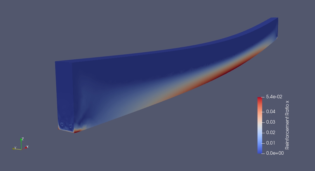
The required reinforcement in the x direction is very high (5.4%) and exceeds the typical maximum percentages allowed by code to prevent brittle failure. The high shear stresses at the supports also lead to a requirement of high reinforcement:
The Mohr-Coulomb plot shows that the beam is indeed prone to crushing on the compression side (Mohr-Coulomb stress > 0.0), as would be expected with a very high reinforcement percentage:
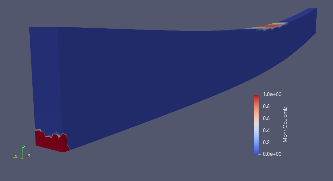
Both the reinforcement ratio and Mohr-Coulomb stress indicate that we have an issue and that we need to rethink our conceptual design. Potential solutions are to increase the beam dimensions or use pre-stressed concrete. Further details can be found in the following post:
https://forum.freecadweb.org/viewtopic.php?f=18&t=28821&start=10#p235003
Beam with mid-span support
A 8.0x0.2x0.4m concrete beam is loaded by self-weight and a 160kN (20kN/m) distributed load.
The material parameters are as follows:
for concrete:
- Young’s modulus = 32 GPa (as per CalculiX default for concrete)
- Poisson ratio = 0.17 (as per CalculiX default for concrete)
- uniaxial compressive strength = 25 MPa (concrete type B25)
- friction angle = 30 degrees
for steel:
- yield strength = 286 MPa (reduced from 500 MPa to account for a safety factor of 1.75)
The specific weight of the concrete is taken as 24 kN/m^3
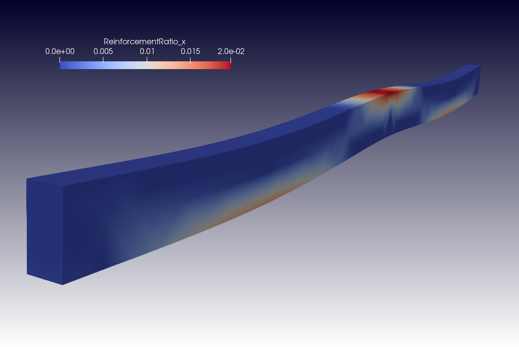
The ParaView plot of the exported VTK file shows that the reinforcement requirement is largest at the top of the beam near the central support. Here the highest bending moment occurs. The maximum reinforcement ratio of 0.02 is at the high end of the practical range quoted earlier:
The required area of steel at the central support can be obtained with a ParaView integration filter applied to the mid-section of the beam:
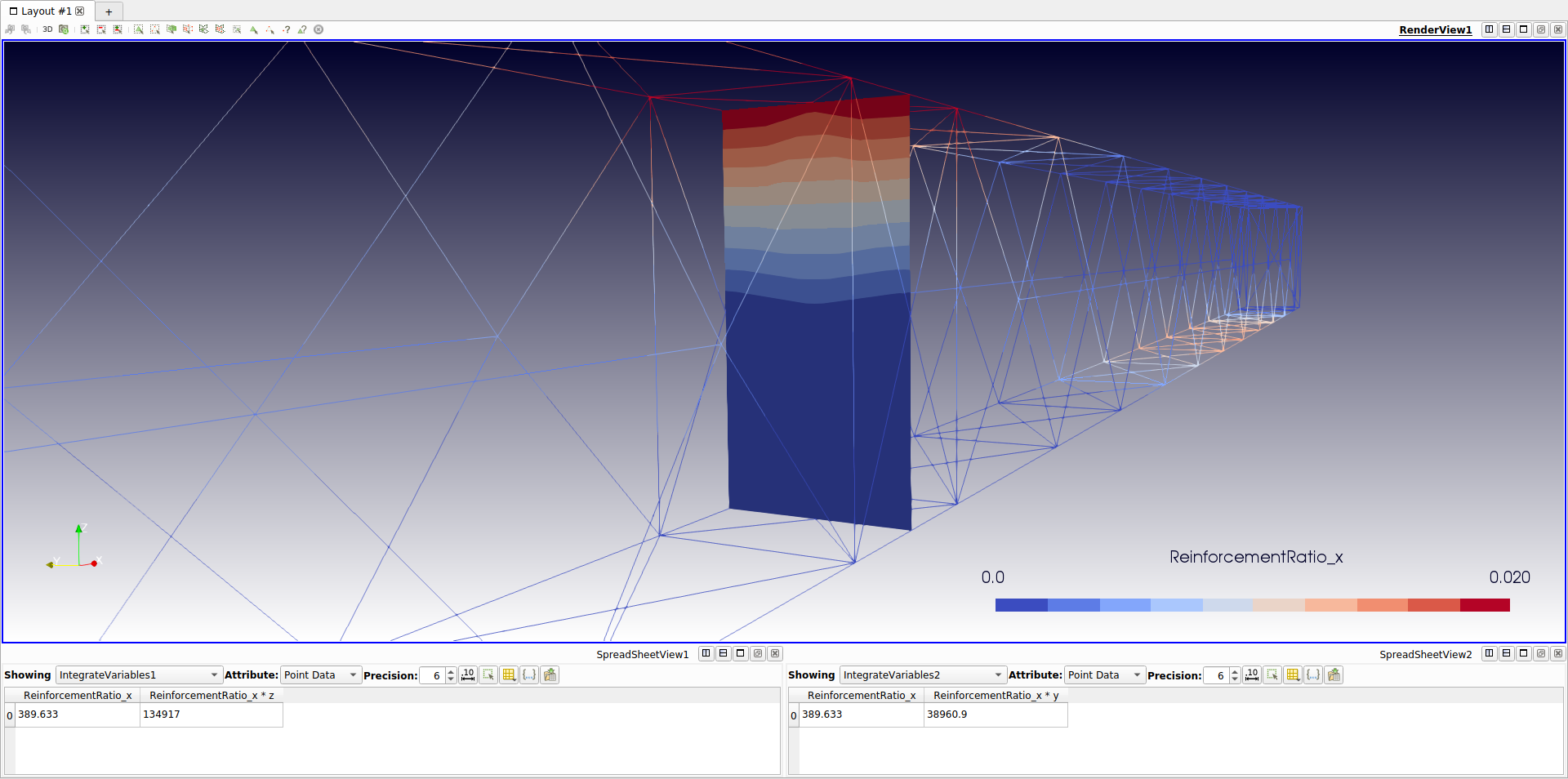
The panel at the bottom of this picture shows that the total required steel area at this cross section is 389.6 mm^2. As one reinforcement bar of diameter 12mm has a cross-sectional area of 113mm^2, it means that 4 bars would be required, giving a cross-sectional area of 452 mm^2. These would need to be placed near the top of the beam while maintaining sufficient concrete cover. The theoretical center of gravity for the reinforcement can be found by integration:
CoG_y = Integrate (rx * y dy dz) / Integrate (rx dy dz)
CoG_z = Integrate (rx * z dy dz) / Integrate (rx dy dz)
These integrals can also be determined with ParaView and give for the present case (see bottom panels in the above picture):
CoG_y = 38961 / 389.6 = 100.0 mm
CoG_z = 134917 / 389.6 = 346.3 mm
which is, as expected, center-width and near the top.
The reinforcement requirement found above agrees well with that obtained using traditional methods:
https://forum.freecadweb.org/viewtopic.php?f=18&t=28821&start=20#p235063
Finally, a Mohr-Coulomb stress check should be performed to check the potential crushing of the concrete. For this check, the characteristic compressive strength of concrete (25MPa) should be divided by an appropriate material factor (>1.0).
Shear wall with uniform load
A 4.0x2.0x0.15m wall is supported by two 0.5m wide columns. The wall is loaded by self-weight and a 1.0MN distributed load at the top.
The material parameters are as follows:
for concrete:
- Young’s modulus = 32 GPa (as per CalculiX default for concrete)
- Poisson ratio = 0.17 (as per CalculiX default for concrete)
- uniaxial compressive strength = 20 MPa
- friction angle = 30 degrees
for steel:
- yield strength = 286 MPa
The specific weight of the concrete is taken as 24 kN/m^3
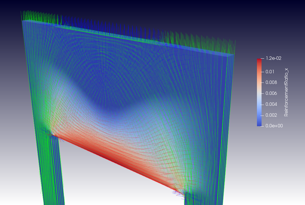
The horizontal reinforcement ratio peaks at 0.014 (1.4%) near the bottom center section of the wall and the vertical reinforcement ratio is at a maximum 0.008 (0.8%) near the corners of the wall with the columns, where the shear stresses are highest:
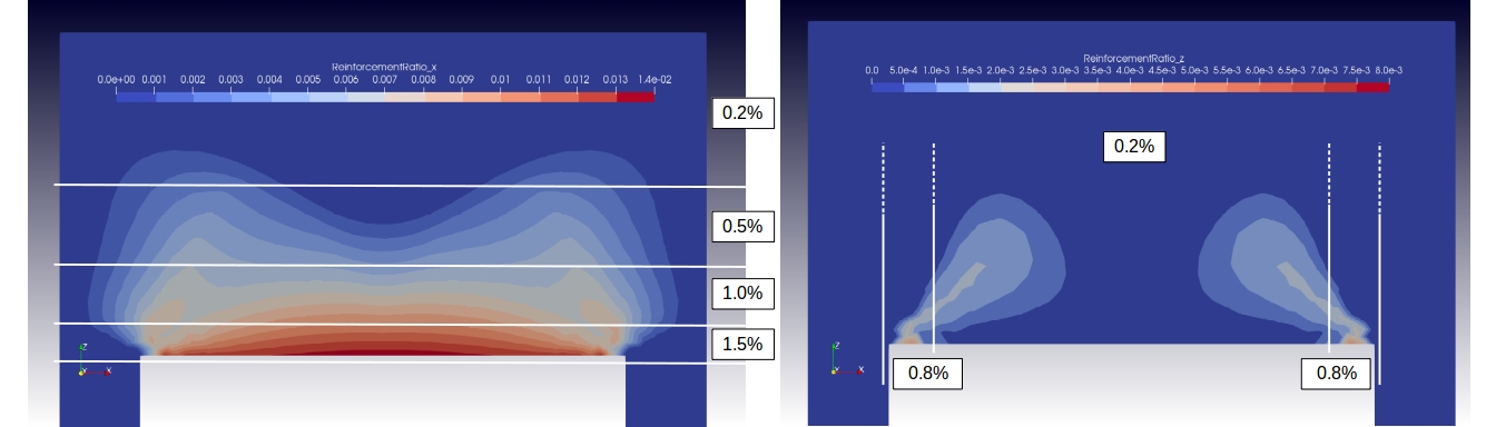
The above picture shows possible zones of constant reinforcement ratio for the design of reinforcement. Although a minimum reinforcement percentage of 0.2% is chosen, it will be hard to achieve such a low value in practice, given that the spacing should not exceed a practical limit (say 300mm). Even with a light reinforcement grid of 10mm bars (cross-sectional area = 78mm^2), the reinforcement ratio would then be 2 * 78 / (150 * 300) = 0.0035 (0.35%). (Note: factor 2 stems from the fact that the grid will be placed at both faces of the wall). If we add one more bar to the grid (halving the distance) the reinforcement ratio would double to 0.7% and one more would give approximately 1%. So most of the reinforcement requirement could be achieved by starting with a grid of d=10mm at 300x300mm spacing and adding bars in horizontal or vertical direction, as required. This would cover all but the requirement at the bottom of the wall, where we could add 3 bars d=12mm, giving a horizontal reinforcement ratio of 3 * 113mm^2 / (150mm * 150mm) = 0.015 (1.5%). Here it is assumed that the height of the bottom zone is 150mm. Alternatively, we could choose 2 bars of 16mm diameter, achieving the same reinforcement ratio for a zone of 180mm height.
Finally, a review of the Mohr-Coulomb stress shows that no concrete crushing is expected in the wall.
https://forum.freecadweb.org/viewtopic.php?f=18&t=28821&start=10#p234673
Deep beam with opening
The FIB Practitioners' Guide to Finite Element Modelling of Reinforced Concrete Structures contains a design example of a deep concrete beam with an opening. The example is used in that report to demonstrate the "Strut-and-Tie" method. Here the results will be compared to those obtained with the FreeCAD FEM Workbench.
The beam dimensions are 11.0x4.0x0.6m and it is loaded at the top by a distributed load of 120kN/m and a load of 5000kN introduced by a 1m wide column. The factored compressive strength of the concrete is 0.75 x 0.6 x fc = 0.45 * 35 = 15.8MPa and the factored yield strength of the reinforcement steel is 315MPa.
The reinforcement ratios and principal concrete stresses (compression only) derived with FreeCAD are shown below:
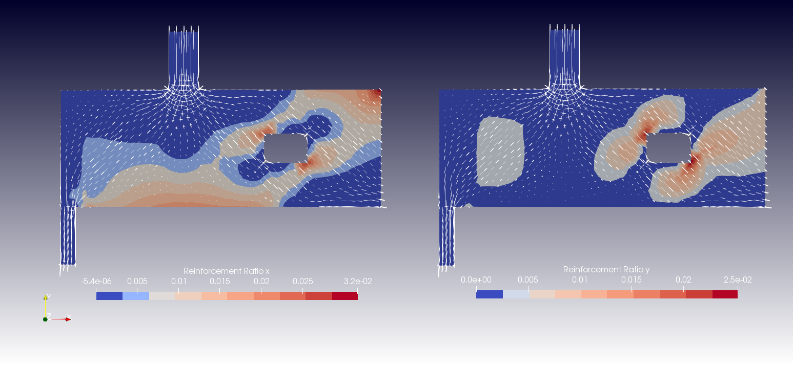
The required horizontal reinforcement (below in red) is determined by integration of the horizontal reinforcement ratio over the vertical cuts of interest (below in black). This is done using a Paraview integration filter.
.jpg)
The insert to the above figure shows a comparison of reinforcement requirements (in mm^2 of steel) determined with FreeCAD to those in the FIB report.
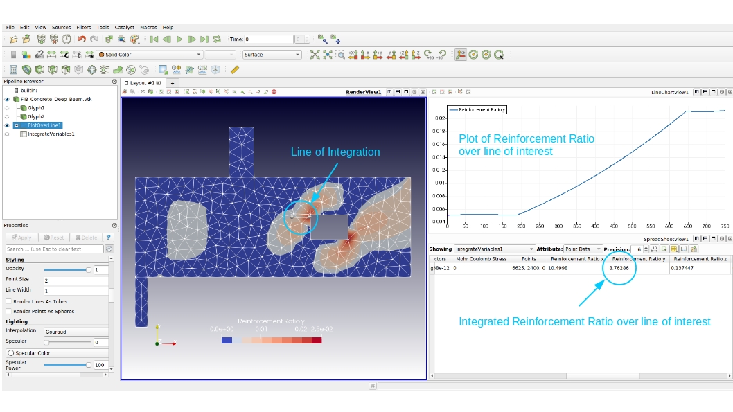
The following shows how the integration over lines of interest works in Paraview:
Finally, a plot of compressive and tensile principal stresses to demonstrate how stresses flow through the beam.
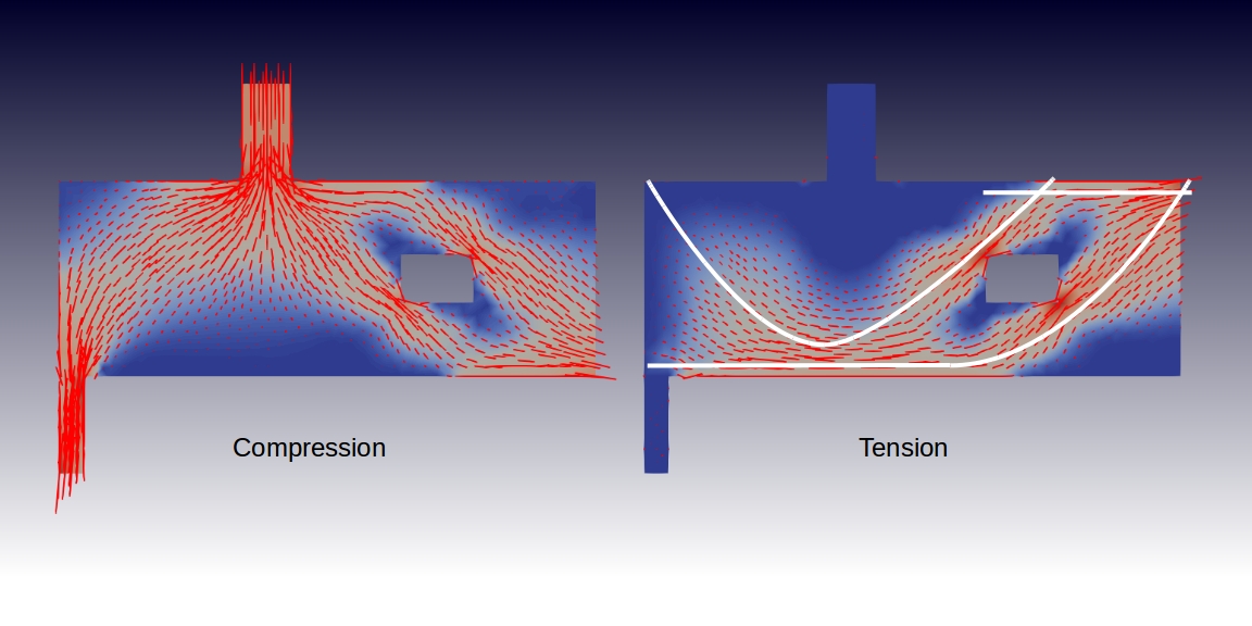
The tensile stress pattern suggests an alternative design concept using pre-stressing cables (superimposed in white). This concept is further elaborated in the following post: https://forum.freecadweb.org/viewtopic.php?f=18&t=33049
Related
- Materials: Solid, Fluid, Nonlinear mechanical, Reinforced (concrete); Material editor
- Element geometry: Beam (1D), Beam rotation (1D), Shell (2D), Fluid flow (1D)
Constraints
- Electromagnetic: Electrostatic potential, Current density, Magnetization
- Geometrical: Plane rotation, Section print, Transform
- Mechanical: Fixed, Displacement, Contact, Tie, Spring, Force, Pressure, Centrif, Self weight
- Thermal: Initial temperature, Heat flux, Temperature, Body heat source
- Overwrite Constants: Constant vacuum permittivity
- Solve: CalculiX Standard, Elmer, Mystran, Z88; Equations: Deformation, Elasticity, Electrostatic, Electricforce, Magnetodynamic, Magnetodynamic 2D, Flow, Flux, Heat; Solver: Solver control, Solver run
- Results: Purge, Show; Postprocessing: Apply changes, Pipeline from result, Warp filter, Scalar clip filter, Function cut filter, Region clip filter, Contours filter, Line clip filter, Stress linearization plot, Data at point clip filter, Filter function plane, Filter function sphere, Filter function cylinder, Filter function box
- Additional: Preferences; FEM Install, FEM Mesh, FEM Solver, FEM CalculiX, FEM Concrete; FEM Element Types
- Getting started
- Installation: Download, Windows, Linux, Mac, Additional components, Docker, AppImage, Ubuntu Snap
- Basics: About FreeCAD, Interface, Mouse navigation, Selection methods, Object name, Preferences, Workbenches, Document structure, Properties, Help FreeCAD, Donate
- Help: Tutorials, Video tutorials
- Workbenches: Std Base, Assembly, BIM, CAM, Draft, FEM, Inspection, Material, Mesh, OpenSCAD, Part, PartDesign, Points, Reverse Engineering, Robot, Sketcher, Spreadsheet, Surface, TechDraw, Test Framework
- Hubs: User hub, Power users hub, Developer hub