Part Revolve/es
|
|
| Ubicación en el Menú |
|---|
| Part → Revolve |
| Entornos de trabajo |
| Pieza, Completo |
| Atajo de teclado por defecto |
| Ninguno |
| Introducido en versión |
| - |
| Ver también |
| Ninguno |
Description
Revoluciona los objetos seleccionados alrededor de un eje dado. Los siguientes tipos de formas están permitidos, y crean las formas de salida indicadas:
| Forma de entrada | Forma de salida |
|---|---|
| Vértice | Arista |
| Arista | Cara |
| Contorno | Cáscara |
| Cara | Sólido |
| Cáscara | Sólido compuesto |
Los sólidos o sólidos compuestos no están permitidos como formas de entrada. Los componentes perpendiculares tampoco están permitidos. Las versiones futuras comprobarán el tipo actual de forma de los objetos compuestos.
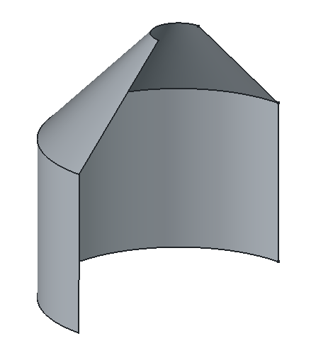
Example of revolution
Usage
- Optionally select one or more shapes in the 3D View or in the Tree View.
- There are several ways to invoke the command:
- Press the
Revolve button.
- Select the Part →
Revolve option from the menu.
- Press the
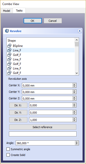
- The Revolve task panel opens.
- Optionally click on an item in the Shape list to (re-) select a shape.
- Optionally keep Shift pressed and click on an item in the Shape list to either add the shape to the selection, or to remove it from the selection.
- Set the revolution axis and angle and optionally other parameters (see Properties for more details).
- Press OK to close the task panel.
- One Revolve object will be created for each selected shape.
Each input shape is placed underneath its Revolve object.
Task panel

Notes
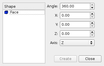
- The Angle argument specifies how far the object is to be turned. The coordinates move the origin of the axis of revolving, relative to the origin of the coordinate system.
- If you select a user defined axis, the numbers define the direction of the revolving axis with respect to the coordinate system: if the Z-coordinate is 0 and the Y and X-coordinates are non-zero, then the axis will lie in the X-Y plane. Its angle is such that its tangent is the ratio of the given X and Y-coordinates.
- App Link objects linked to the appropriate object types can also be used as shapes and to specify the axis.
- If the object to revolve intersects the rotation axis the operation will fail in most cases.
Properties
See also: Property View.
A Part Revolve object is derived from a Part Feature object and inherits all its properties. It also has the following additional properties:
Data
Extrude
- DatosSource (
Link): The shape to revolve. - DatosBase (
Vector): The base point of the revolution axis. - DatosAxis (
Vector): The direction of the revolution axis. - DatosAxis Link (
LinkSub): Link to the edge to use as the revolution axis. Overrides DatosBase and DatosAxis if set. - DatosAngle (
Angle): The angle span of the revolution. If zero and an arc is used for the DatosAxis Link, the arc's span will be used. - DatosSymmetric (
Bool): If true, the revolution is extended symmetrically from the profile. - DatosSolid (
Bool): If true, revolving a closed edge or a closed wire will yield a solid. If False, a shell will result. - DatosFace Maker Class (
String): If DatosSolid is true, the facemaker class to use when converting wires to faces, otherwise ignored.
- Primitives: Box, Cylinder, Sphere, Cone, Torus, Tube, Create primitives, Shape builder
- Creation and modification: Create sketch, Extrude, Revolve, Mirror, Scale, Fillet, Chamfer, Make face from wires, Ruled Surface, Loft, Sweep, Section, Cross sections, 3D Offset, 2D Offset, Thickness, Projection on surface, Color per face
- Boolean: Make compound, Explode compound, Compound Filter, Boolean, Cut, Union, Intersection, Connect objects, Embed object, Cutout for object, Boolean fragments, Slice apart, Slice to compound, Boolean XOR, Check geometry, Defeaturing
- Other tools: Import CAD file, Export CAD file, Box selection, Create shape from mesh, Create points object from geometry, Convert to solid, Reverse shapes, Create simple copy, Create transformed copy, Create shape element copy, Refine shape, Set tolerance, Persistent section cut, Attachment…
- Preferences: Preferences, Fine tuning
- Getting started
- Installation: Download, Windows, Linux, Mac, Additional components, Docker, AppImage, Ubuntu Snap
- Basics: About FreeCAD, Interface, Mouse navigation, Selection methods, Object name, Preferences, Workbenches, Document structure, Properties, Help FreeCAD, Donate
- Help: Tutorials, Video tutorials
- Workbenches: Std Base, Assembly, BIM, CAM, Draft, FEM, Inspection, Material, Mesh, OpenSCAD, Part, PartDesign, Points, Reverse Engineering, Robot, Sketcher, Spreadsheet, Surface, TechDraw, Test Framework
- Hubs: User hub, Power users hub, Developer hub

