Release notes 0.20/it
FreeCAD 0.20 è stato rilasciato il 14 giugno 2022, scaricalo dalla pagina di Download. Questa pagina elenca tutte le nuove funzionalità e modifiche.
Le note di rilascio precedenti di FreeCAD possono essere trovate nella lista delle funzionalità.
|
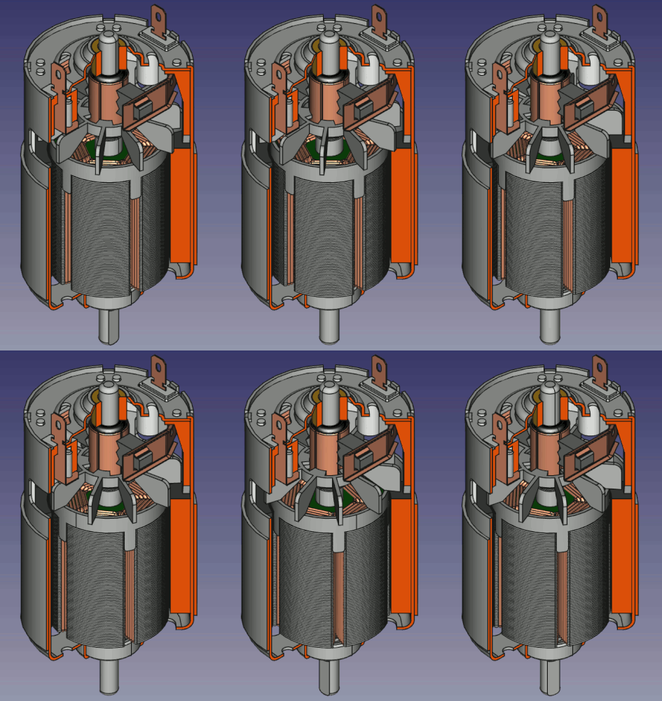
Model of a 775 DC motor by user "jimmihenry", see Users Showcase. The model was made completely with the weekly development snapshots of FreeCAD 0.20. The pictures for the animated graphic were made with the FreeCAD macro Screen Wiki. The animated GIF itself was made using GIMP. For the release notes it was cropped and resized using ezgif. |
Generale
freecad.org
Siamo felici che il progetto KiCAD, attraverso KiCAD services corp., ci abbia sponsorizzato il dominio freecad.org. Ora tutti i siti Web di FreeCAD sono disponibili in freecad.org e freecad.org.
Bug/Issue tracker
Il bug tracker di FreeCAD è stato spostato su GitHub: https://github.com/FreeCAD/FreeCAD/issues
Nota: Verranno prese in considerazione solo le segnalazioni di bug con una precedente discussione nel forum. I report senza questa condizione verranno chiusi.
Nuovo sistema di help
Il sistema di aiuto è stato riscritto e aggiornato per visualizzare le informazioni direttamente dal nostro Wiki. Il sistema ora si basa sul Help Addon. Quando utilizzi per la prima volta lo strumento Aiuto o lo strumento Cos'è questo? ti verrà chiesto di installarlo.
Interfaccia utente
|
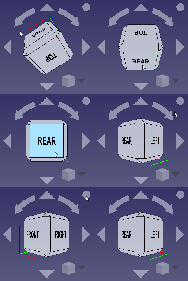
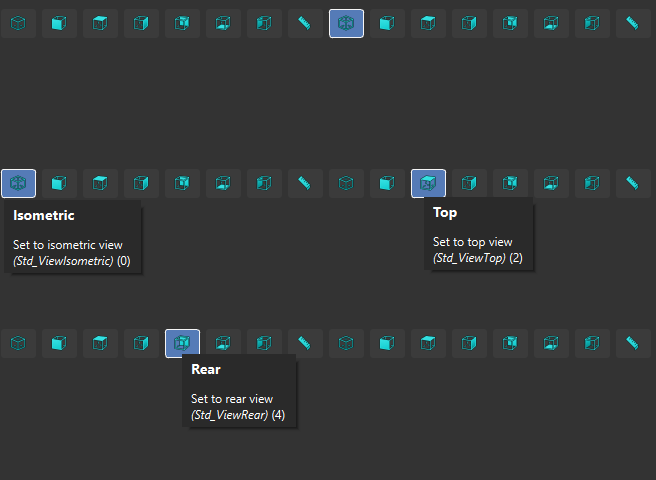
The navigation cube was reworked:
|
|
Tooltips now display the command name in the title, making it easier for new users to look for help. At the end of the tooltip the "internal" command name is added in parentheses: (Std_WhatsThis). This is also the name of the page that documents the command in the Wiki. Forum discussion, Pull request #4978 . |
|
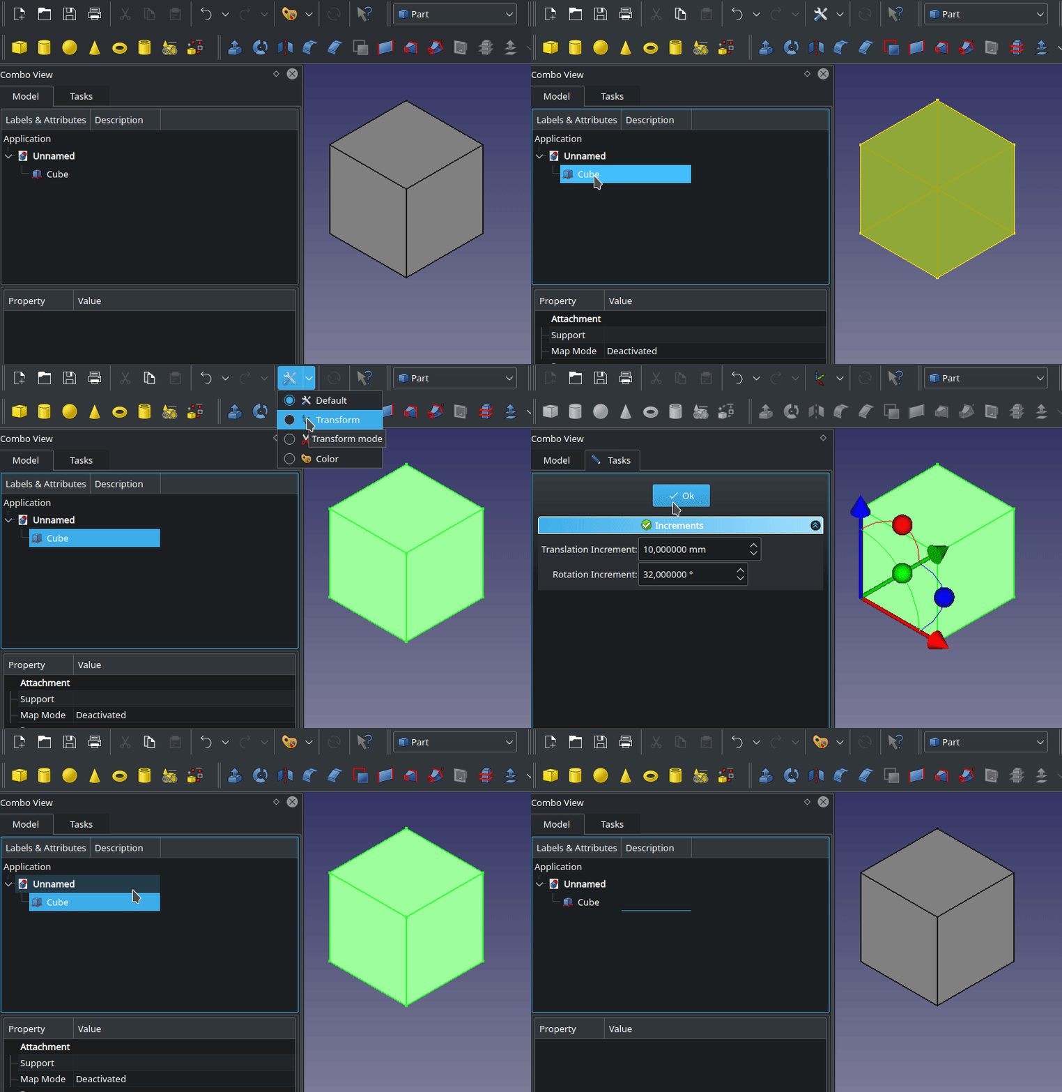
The new Std UserEditMode command allows the user to choose an edit mode that will be used when an object is double-clicked in the Tree view. Click the image on the left so see an animation of the selection. If a selected edit mode is not applicable, the object's default edit mode is used instead. Pull request #5110. |
|
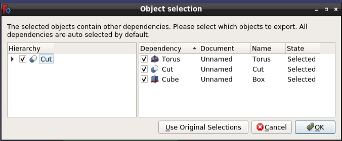
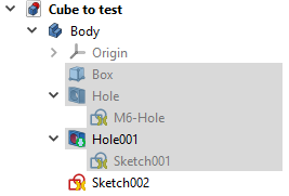
The Tree view context menu has the new entry Add dependent objects to selection. Forum discussion, Pull request #4133. In the image the Hole001 object was selected and then its |
|
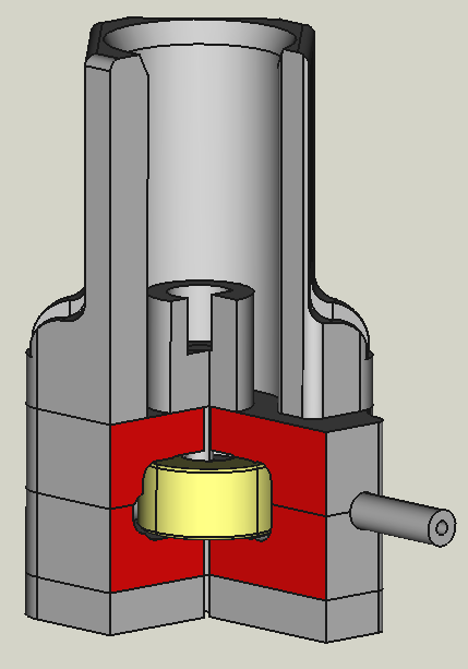
The new tool Section Cut allows to get non-hollow and also persistent cuts of parts and assemblies. Forum discussion, Pull request #4118. |
Ulteriori miglioramenti dell'interfaccia utente
- It is now possible to use the decimal separator belonging to the language specified for the FreeCAD interface. For example on a German Windows, when you set the interface language to English and select the new option Use selected language number format, the dot will be used as the decimal separator. See Preferences. Pull request #6364
Note: For FEM simulations using the dot as decimal separator is highly recommended to get correct results. - Two new mouse navigation styles have been added. One based on OpenSCAD, the other on TinkerCAD. Forum discussion OpenSCAD, Forum discussion TinkerCAD, commit 1, commit 2, commit 3.
- It is now possible to pan the view of the dependency graph with the mouse. Forum discussion, Pull request #4638.
- Fixed an issue where using tablet pen devices (e.g. Wacom tablet) was slow to the point of being completely unusable. Forum discussion, Pull request #4687.
- The coordinate system in the 3D view can be resized in the preferences in the section Display → 3D View. Pull request #5182
- A new setting in Preferences → General allows to substitute the numerical keypad decimal separator with the appropriate locale separator if they are different. Pull request #3256 Pull request #5150 Pull request 5203
- It is now possible to set the Backspace key as a standalone shortcut key without the need to specify an additional modifier key. Pull request #5428
Sistema principale e API
Sistema principale
|
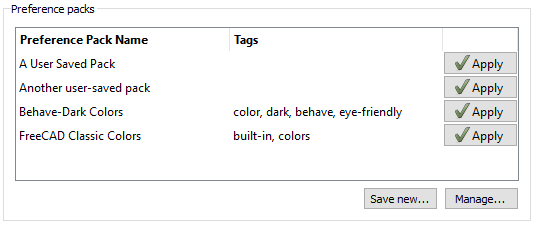
A new type of add-on called a Preference Pack was added, allowing a subset of a user preferences file (user.cfg) to be saved, distributed, and easily applied by other users. Preference Packs can be use to distribute "Themes," for example, by allowing a developer to include both a Qt stylesheet for widgets as well as a set of other colors and styles for items in the user interface that cannot be set using a stylesheet (e.g. text colors in the Python editor or report view, etc.). Anything that can be configured via a user.cfg file can be set using a Preference Pack. Forum discussion |
|
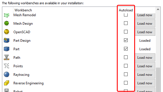
The "Workbenches" preference panel was modified to support the ability to "autoload" workbenches on FreeCAD startup. |
On Linux, the default location of FreeCAD's configuration, data and cache files was changed to follow the XDG Base Directory Specification. Forum discussion. Here is a comparison of the old and new locations:
| Description | Old location | New location | Defaults to |
|---|---|---|---|
| Configuration files | $HOME/.FreeCAD | $XDG_CONFIG_HOME/FreeCAD | $HOME/.config/FreeCAD |
| Data files | $HOME/.FreeCAD | $XDG_DATA_HOME/FreeCAD | $HOME/.local/share/FreeCAD |
| Cache files | /tmp | $XDG_CACHE_HOME/FreeCAD | $HOME/.cache/FreeCAD |
If you wish to keep using the old locations you may start FreeCAD with the --keep-deprecated-paths option.
API
FreeCAD ha adottato molte nuove funzioni API Python:
Nuove API Python
- ChFi2d_AnaFilletAlgoPy: An analytical algorithm for the calculation of fillets. commit f94ab3ec
- ChFi2d_ChamferAPIPy: Algorithm that creates a chamfer between two linear edges. commit 30f8015e7
- Circle2dPy::getCircleCenter: Gets the circle center defined by three points. commit 3dc91fa2
- ComplexGeoDataPy::applyRotation: Applies an additional rotation to the placement. commit 32592de8
- ComplexGeoDataPy::applyTranslation: Applies an additional translation to the placement. commit 32592de8
- ComplexGeoDataPy::countSubElements: Returns the number of elements of a type. commit 32592de8
- ComplexGeoDataPy::getElementTypes: Returns a list of element types. commit 32592de8
- ComplexGeoDataPy::getFaces: Returns a tuple of points and triangles with a given accuracy. commit 32592de8
- ComplexGeoDataPy::getLines: Returns a tuple of points and lines with a given accuracy. commit 32592de8
- ComplexGeoDataPy::getLinesFromSubelement: Returns vertexes and lines from a sub-element. commit 32592de8
- ComplexGeoDataPy::getPoints: Returns a tuple of points and normals with a given accuracy. commit 32592de8
- ComplexGeoDataPy::transformGeometry: Applies a transformation to the underlying geometry. commit 32592de8
- ControlPy::showModelView: Shows the model view. commit 033bf619
- DocumentPy::clearDocument: Clears the whole document. commit 526dc1a0
- DocumentPy::getFileName: For a regular document it returns its file name property. For a temporary document it returns its transient directory. commit 526dc1a0
- DocumentPy::getProgramVersion: Gets the program version that a project file was created with. commit 526dc1a0
- DocumentPy::isClosable: Checks if the document can be closed. commit 526dc1a0
- DocumentPy::isSaved: Checks if the document is saved. commit 526dc1a0
- DocumentPy::isTouched: Checks if any object is in touched state. commit 526dc1a0
- DocumentPy::mustExecute: Checks if any object must be recomputed. commit 526dc1a0
- DocumentPy::purgeTouched: Purges the touched state of all objects. commit 526dc1a0
- DocumentPy::setClosable: Sets a flag that allows or forbids to close a document. commit 526dc1a0
- DrawPagePy::requestPaint: Paints a TechDraw page. commit 79f9fb68
- HLRBRep_AlgoPy: To access Part's hidden line removal (HLR). commit 73a98671
- HLRBRep_PolyAlgoPy: To access Part's poly hidden line removal (HLR). commit ea85cf5e
- HLRToShapePy: To access Part's hidden line removal (HLR). commit 73a98671
- PolyHLRToShapePy: To access Part's poly hidden line removal (HLR). commit ea85cf5e
- MDIViewPy::printPdf: Prints a PDF. commit c93031da
- MDIViewPy::printPreview: Prints a preview. commit c93031da
- MDIViewPy::printView: Prints a view. commit c93031da
- MDIViewPy::redoActions: Redoes actions. commit c93031da
- MDIViewPy::undoActions: Undoes actions. commit c93031da
- PrecisionPy: To access the precision defined by the OpenCascade kernel. commit 20b86e55
- PropertyContainerPy::setDocumentationOfProperty: Sets the documentation string of a dynamic property of this class. commit 8cf3cf33
- PropertyContainerPy::setGroupOfProperty: Set the name of the group of a dynamic property. commit 8cf3cf33
- PythonWorkbenchPy::reloadActive: Reload the active workbench after changing menus or toolbars. commit 0bbc253d
- RotationPy::fromEuler: Sets the Euler angles of a rotation or gets the Euler angles in a given sequence for a rotation. commit 951a0be9
- RotationPy::toEulerAngles: Gets the Euler angles in a given sequence for this rotation. commit c1454dfb
- SpreadsheetViewPy: To access spreadsheets. commit 6e713628
- UnitsApi::sToNumber: Converts a quantity or float to a string. commit befbd95d
- View3DInventorPy::getCornerCrossSize: Returns current corner axis cross size. commit 9d15df29
- View3DInventorPy::setPopupMenuEnabled: Enables popup menu. commit 9def811a
- View3DInventorPy::isCornerCrossVisible: Returns current corner axis cross visibility. commit 9d15df29
- View3DInventorPy::isPopupMenuEnabled: Returns if popup menu is enabled. commit 9def811a
- View3DInventorPy::projectPointToLine: Projects the given 2d point to a line. commit b6527a70
- View3DInventorPy::setCornerCrossSize: Defines corner axis cross size. commit 9d15df29
- View3DInventorPy::setCornerCrossVisible: Defines corner axis cross visibility. commit 9d15df29
- ViewProviderSpreadsheetPy: To handle spreadsheet cells.commit 16bbe123 and commit 093f15dc
Changed Python API
- MeshObject::trim(base, normal) was changed to MeshPy::trimByPlane(base, normal): Trims the mesh with a given plane. commit 837de28e
Addon Manager
|
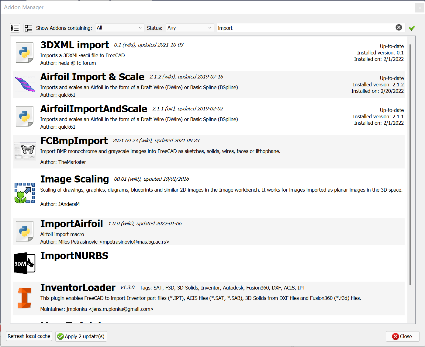
The Addon Manager was modified to support the distribution of Preference Packs, and to display information found in an addon's metadata. The Addon Manager also includes improved support for Addons whose source code is located at several different git hosting locations. Networking support was improved to provide more robust handling of SSL connections and support for proxies requiring authentication. Support was added for automatically adding macro buttons to the toolbar after installing, for disabling Addons without removing them, and for switching which git branch of an Addon is checked out. Finally, the user interface was modified to improve searching and display of different list filters. |
Arch Workbench
|
SketchArch workbench
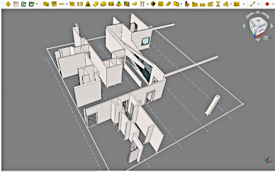
With the |
|
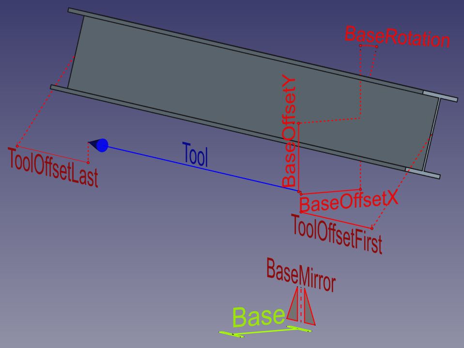
New properties for Arch Structure objects:
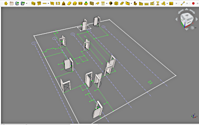
A new command Create multiple Arch Structure was also added. It uses the first selected object as a Base, and creates Arch Structures objects for every Edge of the other selected objects. Then, the properties of individual Structure objects can be adjusted in the Property editor. This command was added for workflow with a master Sketch (there is risk of topological naming problem unless you create non-parametric copy of the master Sketch or use Realthunder's version). Support for 2D data such as linework, hatches, texts and dimensions is now enabled in IFC import and export, which contributes to making the IFC format more and more suitable for traditional 2D CAD work. A similar effort is being made in BlenderBIM. More 2D workflow improvements are documented in this forum thread. |
Draft Workbench
- A Global checkbox was added to the task panel of many drafting commands. Checking it allows input of coordinates in the global coordinate system even if the working plane is not aligned with the global XY plane.
- The
Draft Hatch command was introduced. It creates hatches on the faces of a selected object using patterns from AutoCAD PAT files.
- The
Draft AddNamedGroup command was introduced. The
Draft AddToGroup command was extended with the same functionality.
- Work on the
Draft SetStyle command, still in progress in FreeCAD version 0.19, was completed.
- A double-click edit option was added for
Draft Texts. It opens the same edit task panel used when creating a text.
- For
Draft Dimensions the
archVistaUnit Override for imperial architectural dimensions was introduced.
Draft Shape2DView objects now have an DatiAuto Update property. Setting it to
falsecan be useful if there are many Draft Shape2DViews in a document or if they are complex.
- It is now possible to reverse a Draft Wire via the
Draft Edit context menu. Forum discussion, Pull request #4811.
Further Draft improvements
- Fixed Draft Snap Grid when the cursor is over a face. Forum discussion. Git commit.
- New Draft Texts are now aligned with the working plane, Pull request #5092.
- Support for two DWG converters was added: LibreDWG and QCAD pro. See Import Export Preferences and FreeCAD and DWG Import for more information.
FEM Workbench
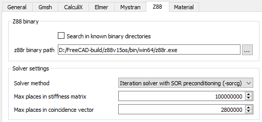 The new Z88 settings and their default values |
The Z88 solver is now fully usable. You can specify the solver method and change the memory settings. The new default values allow you to perform also complex simulations directly. |
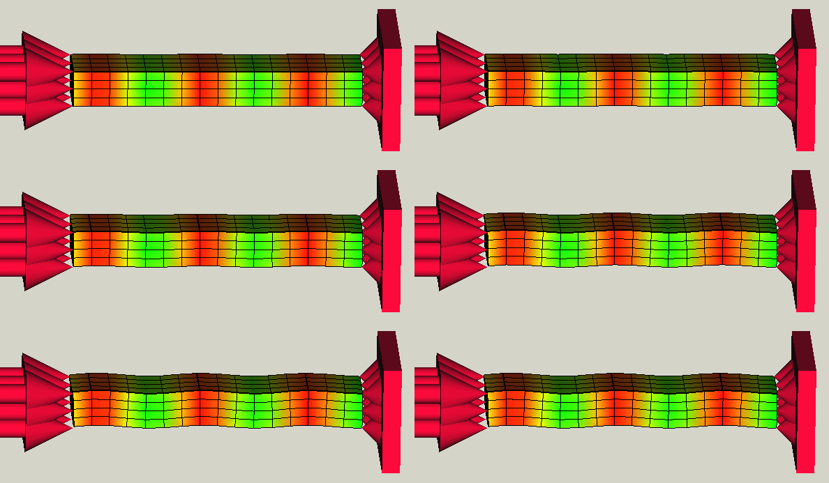 Result of a linear buckling analysis. Click on the image to see the animation. |
It is now possible to perform buckling analyses using the Calculix solver. Pull request #4379 |
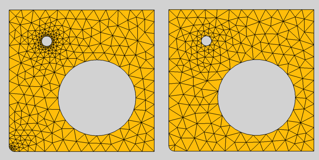 Effect of Mesh Size From Curvature; left: set to 12, right: deactivated |
There is a new property for the Gmsh mesher. The number of mesh elements per times the radius of the curvature can be specified. The default is 12 and to get a finer mesh at small corners or holes, this value can be increased for better results. This feature requires Gmsh 4.8 or newer. |
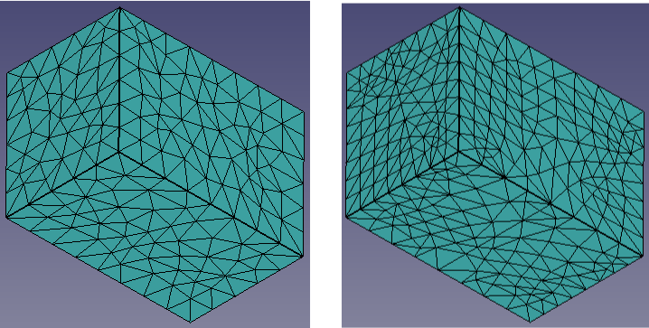 Effect of the recombination algorithm; left: using Simple, right: using Simple full-quad |
FreeCAD now allows to select an algorithm as well as 3D mesh recombination for the Gmsh mesher. For more details about mesh element recombination see FEM MeshGmshFromShape. |
Further FEM improvements
- Important: Starting from this release, FreeCAD will use SI units (m, kg, s, K, A, mol, cd) to write the Elmer solver input files (case.sif and mesh.nodes). This is independent of the used FreeCAD unit system.
- Important: Starting from this release, the scale of result pipelines and their filters will use SI units (m, kg, s, K, A, mol, cd). So the displacement is given in meter, the stress in Pascal. This applies to all SI-derived FreeCAD unit systems.
- Solving with the Calculix solver now uses all CPU cores. Pull request #6374
- Meshing with Gmsh now uses all CPU cores. Pull request #6370
- The element order of Gmsh meshes can be changed via the mesh dialog. Pull request #4660
- The Data at point clip result filter is now actually working: One gets info from result meshes by clicking into them or by specifying a mesh coordinate.
- A new constraint was added: Model → Mechanical Constraints →
Constraint Centrif. Pull request #4738
- A new solver was added: Solve →
Solver Mystran. Multiple commits.
- A new constraint was added: Model → Mechanical Constraints →
Constraint Spring. Pull request #4982
- It is now possible to have result pipelines with several filters, where some take other filters as input, and some take the results directly from the pipeline. commit 708a300b
- Material cards can now contain values for the electrical conductivity. Pull request #4647
- Material cards added for Nitrogen and Argon. Pull request #4649
- Support for the Gmsh mesh algorithms "HXT" (3D) and "Packing Parallelograms" (2D) added. Pull request #4654
- Allow to specify an algorithm for the Gmsh property "High Order Optimize". Pull request #4705
- Nonlinear solid materials with simple hardening can now have an arbitrary number of yield points. Pull request #5024
- Allow modal adding/removal of geometric entities to constraints acting on boundaries. Pull request #5117
- Most FEM constraint dialogs now behave uniformly and provide the same 3D object selection features. Pull request #5391
Export
- DXF: The missing unit block was added to the header14.rub file. Pull request #5793
Mesh
Improved support for NASTRAN GRID elements
The Mesh import tool now supports the high-precision "GRID*" element. The standard-precision "GRID" element was also improved, now supporting both space-delimited numeric input as well as fixed-field-width input, per the NASTRAN95 format documentation.
Further Mesh improvements
Fixed false negatives during self-intersection tests when facets are coplanar: Pull request #5002.
OpenSCAD Workbench
Interoperability with OpenSCAD has been improved, adding support for several operations missing from earlier versions (linear extrude with rotations, rotational extrusions). Several operations are modified to provide improved FreeCAD object equivalents, particularly for twisted extrusions. Surface generation from discrete data was modified to give more OpenSCAD-like results, rather than splined surfaces.
New options were added to support running either FreeCAD, OpenSCAD, or both, in sandboxed environments such as AppImages and Snap packages: data can now be transferred to and from OpenSCAD via the standard temporary directory mechanism, via a user-specified temp directory that both executables have access to, or new to OpenSCAD 2021.1, via a "stdout pipe" mechanism, bypassing temporary files entirely.
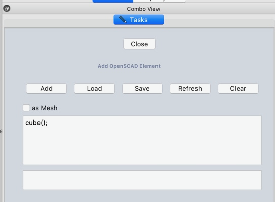
|
The following options were added to the task panel of the Add OpenSCAD element feature:
Load    - load a scad file
Save    - save a scad file
Refresh - Update FreeCAD view
Clear   - Clear text input
A new text box gives feedback about OpenSCAD errors. |
Part Workbench
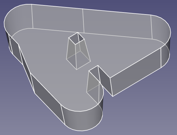 Tapered extrusion of a sketch with an inner structure. |
A tapered extrusion of inner structures now creates usable results. Previously, inner structures were extruded as if they were stand-alone and not part of a structure. |
Further Part improvements
- The dialog to edit Cylinders now allows to specify an angle relative to the normal of the chosen attachment plane. This way one can create skew cylinders. Pull request #4708
- The Face Colors tool now also allows to set the transparency (Alpha channel) of faces. This transparency can be exported, making e.g. STEP files with transparent parts possible.
- The following commands now support App::Links: Loft, Sweep, Extrude, Revolve, Reverse shapes, Mirror, Offset2D, Offset3D, Check Geometry, Ruled Surface, Cross-sections, and Thickness. Pull request #6478
PartDesign Workbench
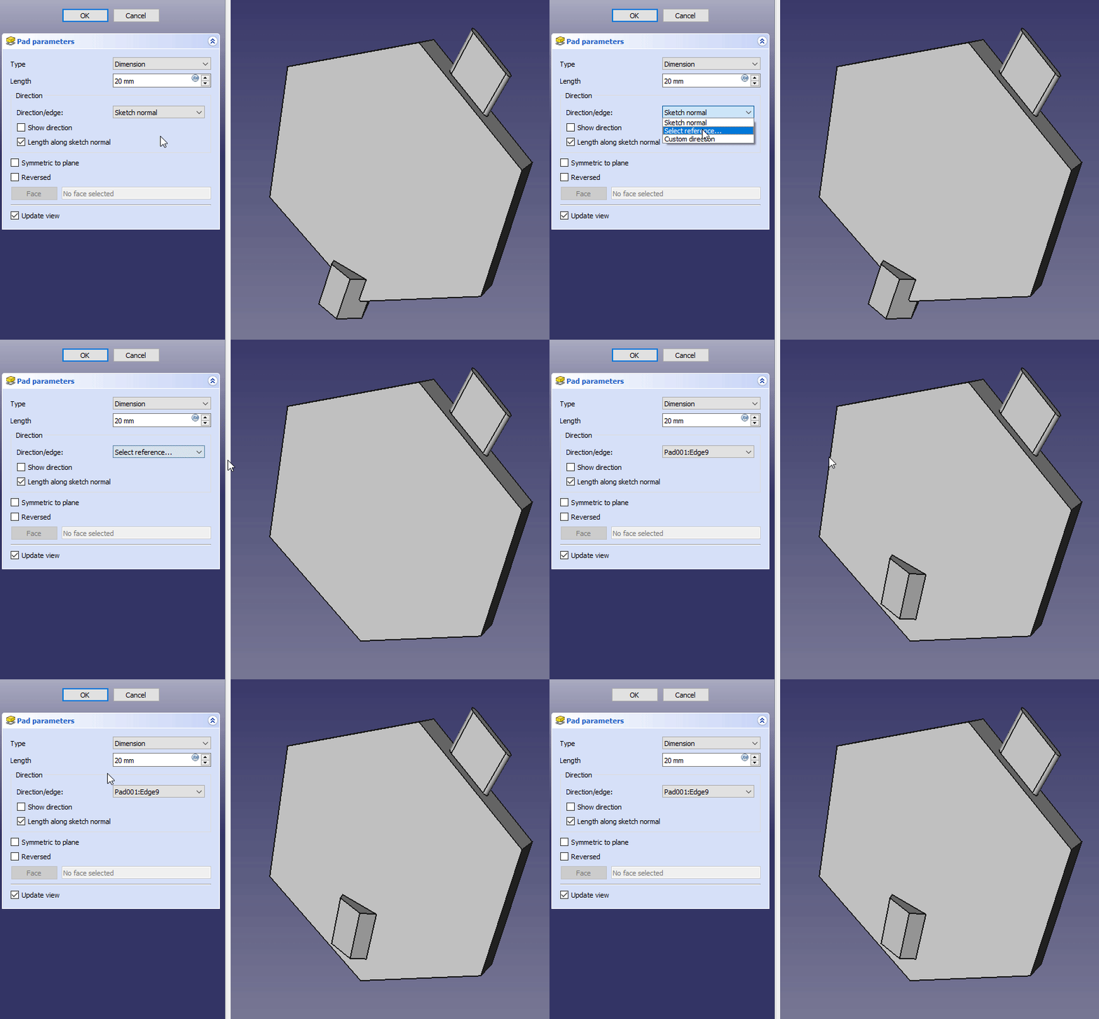 Padding along an edge from the model. Click on the image to see the animation. |
There is a new option to Pad along the direction of an edge in the 3D model. |
|
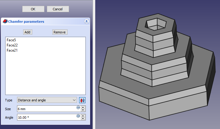
When Distance and Angle is specified in the Chamfer tool and faces are selected, the distance will be applied along the selected faces. Likewise if two distances are specified then Size 1 will be applied along the selected face.
This behaviour can be swapped to the other face using the flip direction button. Forum discussion, Pull request #5039 |
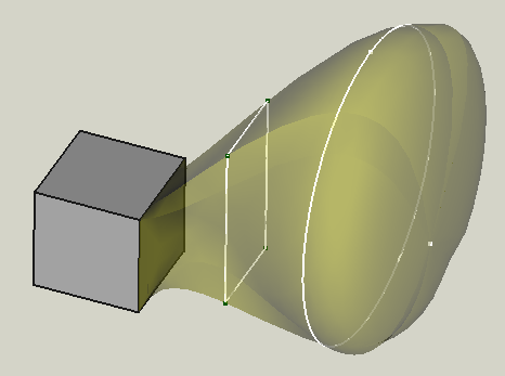 A loft with multiple sections, the final one is a vertex. |
It is now possible to create an Additive or Subtractive Loft, or an Additive or Subtractive Pipe towards, or from, a Vertex of either a sketch or a body. This allows to create pyramids for example. Note: Vertices in sketches are created as construction geometry. To use them as endpoints of lofts, you must first change them to normal geometry. Pull request #5170 (for lofts), Pull request #5193 (for pipes) |
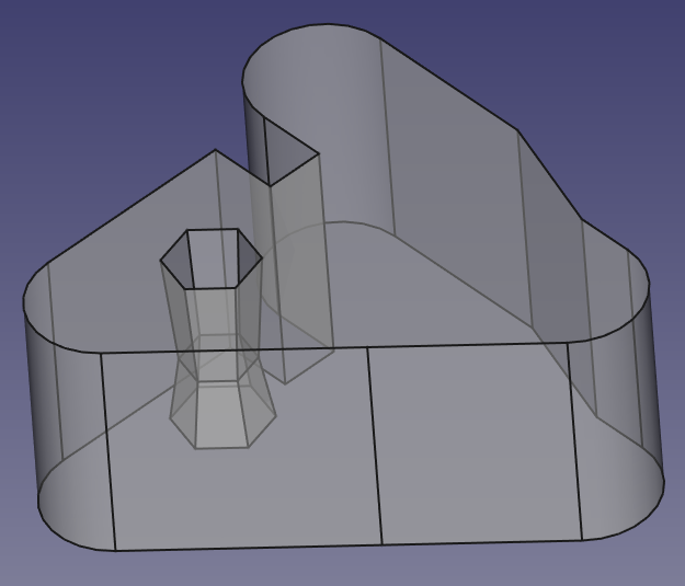 A tapered pocket within a non-tapered pad. |
The dialog for Pad and Pocket offers to set a taper angle for the extrusion. |
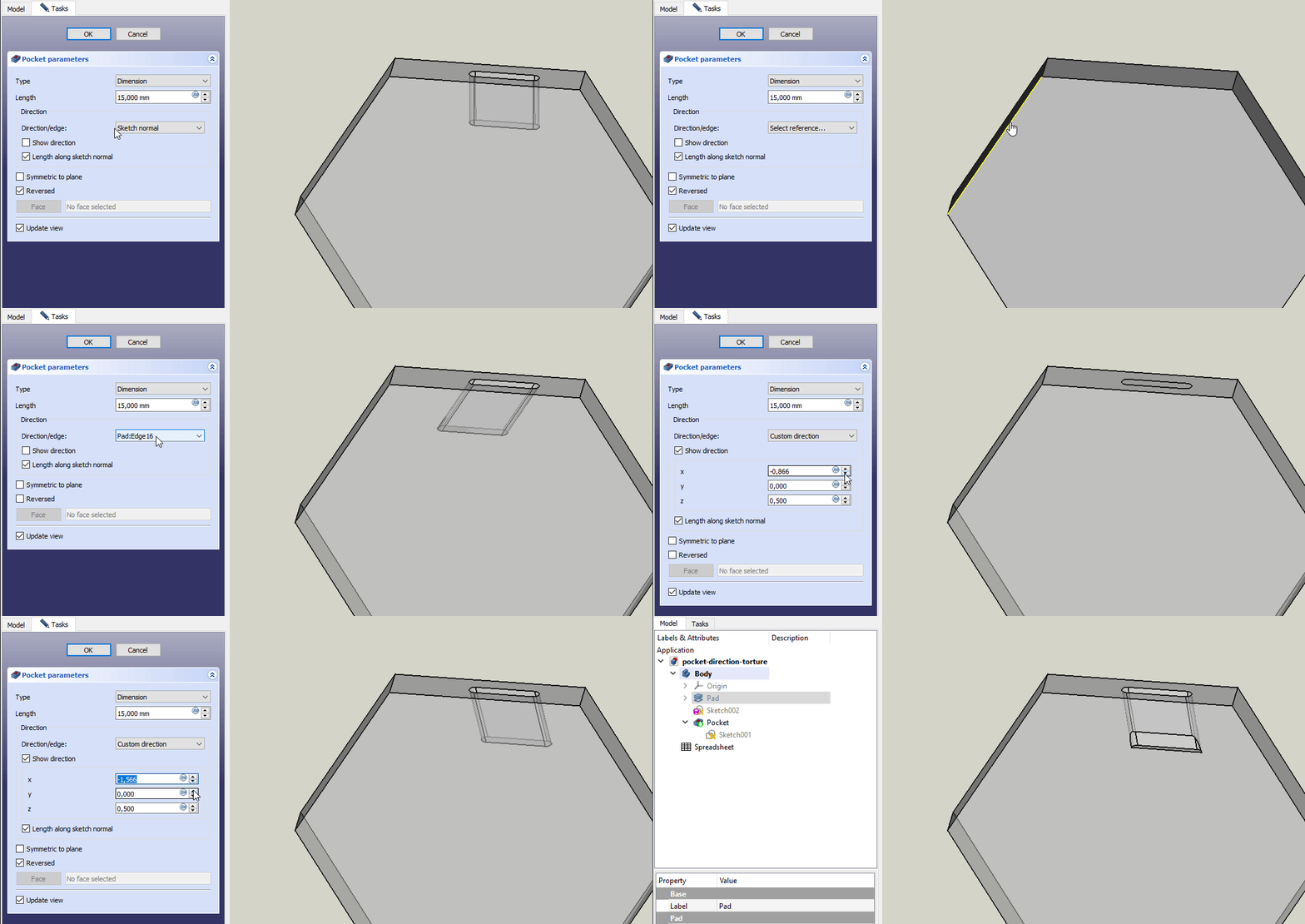 Pocketing along different directions. Click on the image to see the animation. |
It is now possible to specify the direction for the Pocket extrusion. |
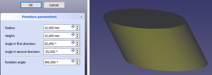
|
The dialog to edit Cylinders (additive and subtractive) now allows to specify an angle relative to the normal of the chosen attachment plane. This way one can create skew cylinders. Pull request #4708 |
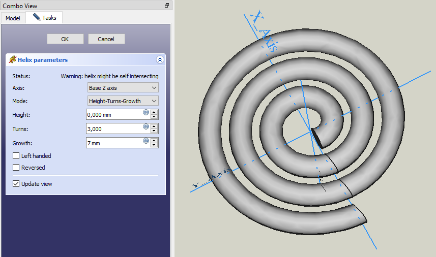
|
The Helix feature has the new mode Height-Turns-Growth to create flat spirals. |
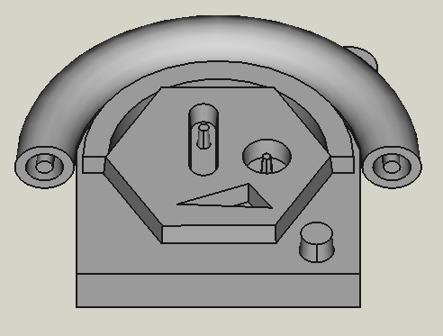 A single Pad and a single Revolution with nested profiles. The base block is only there to ensure that the part is a single solid. |
All PartDesign features that can extrude sketches can now handle sketches with nested profiles that form islands. For example it is possible to Revolve a sketch consisting of 3 nested circles with the same center point. Note: Extruding nested profiles only works if the result is still a single body. |
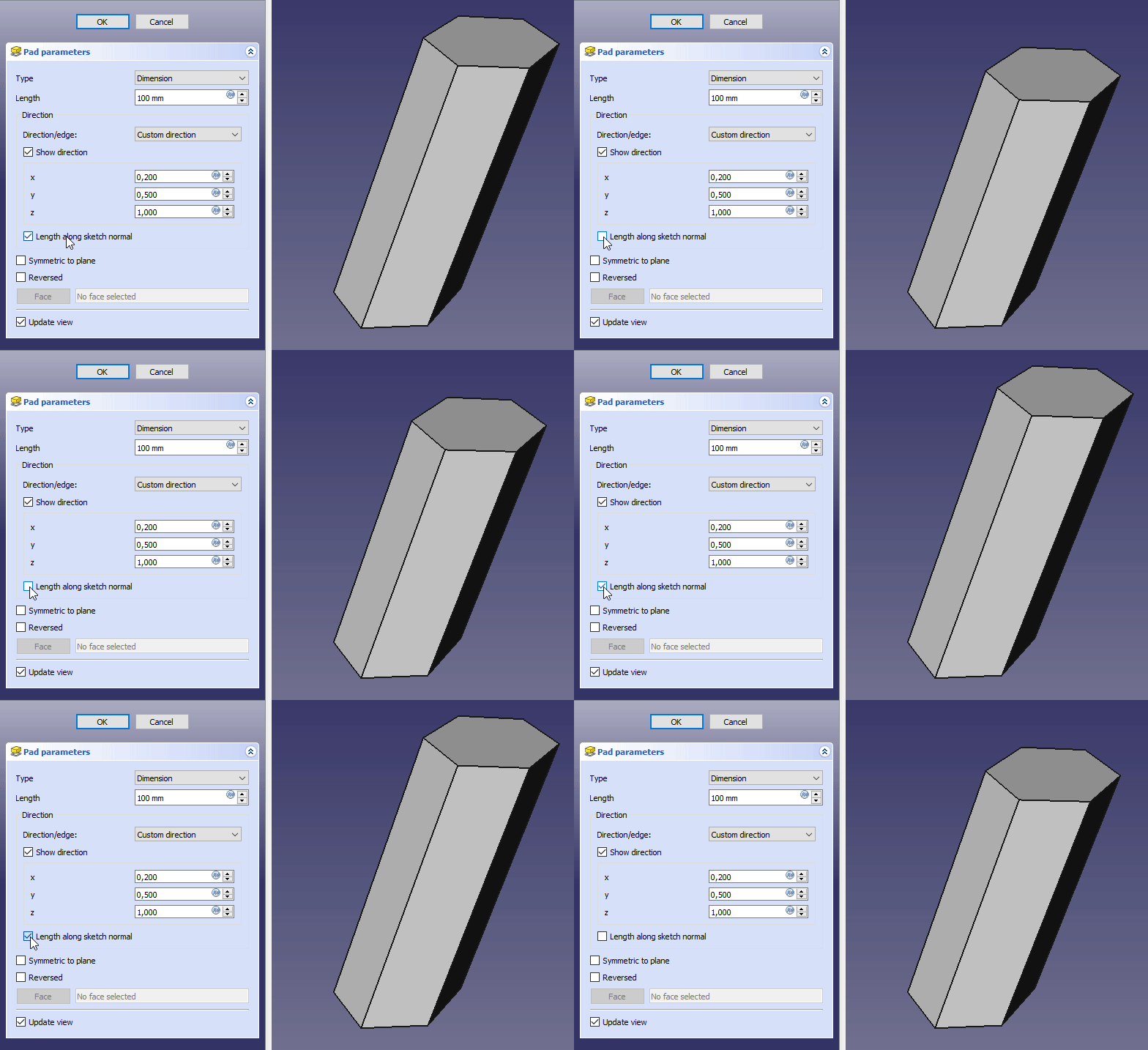 Effect of the new option Length along sketch normal. Click on the image to see the animation. |
There is a new option to Pad a certain length along the direction. The length is either measured along the sketch normal or along the custom direction. |
| The Hole feature can now model true threads. |
Further PartDesign improvements
- In the Helix feature one can now also use the sketch normal as axis. Pull request #5199
- The Sprocket feature can now also create ISO-normed sprockets. Forum thread Pull request #4478
- The Loft and Pipe features now allow using the body's faces for sections. Pull request #5155
- It is now possible to select several faces before calling the Pad or Pocket dialog. In this case the first selected face will be used to determine the default padding/pocketing direction. commit d34a5616
- It is possible to offset SubShapeBinders if they are based on edges, wires or faces. Pull request #6338
- SubShapeBinders now have the Refine property like all other PartDesign objects. Pull request #6550
- In the Chamfer and Fillet dialogs all edges of a body can be selected via the context menu while in Add mode. Pull request #5269
When you selected a 3D object before clicking the icon to create a fillet or chamfer, all object edges will automatically be selected. Pull request #5328 - Chamfer and Fillet dialogs now each have a new Use all edges checkbox, which is connected to the Use All Edges property for these objects. When the box is checked the property is set to True, when unchecked the property is set to False. When Use All Edges is True there is protection against the topological naming problem because then all of the edges of the base object are used regardless of how many edges there are. Pull request #5340
- Plane selection when adding a new sketch can now be achieved with a single-click in the 3D View. Pull request Forum discussion
- When a PartDesign tool is run without an active body, FreeCAD now offers to activate a body or create a new one. Pull request #4949
- The Face Colors tool is now also available from the PartDesign workbench.
Path Workbench
- The Extensions feature was added to the Adaptive operation. Pull request #4388
- The Helix operation was refactored and Extra offset property was added to it. Pull request #5405
- The check if the current schema is using minutes for velocity expression and appropriate warning were added. Pull request #6357
- External threads were added to the thread milling operation. Pull request #6485
- The stability of engraving on sketches was improved. Pull request #6394
- The visibility of path objects was made more natural. Pull request #4911
Plot module
- FreeCAD now provides the Plot module by default, so any other module/workbench may create plots without requiring external tools Pull request #4971.
Sketcher Workbench
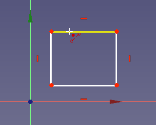
|
New |
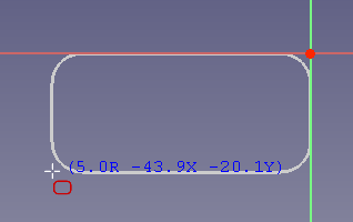
|
New |
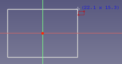
|
New |
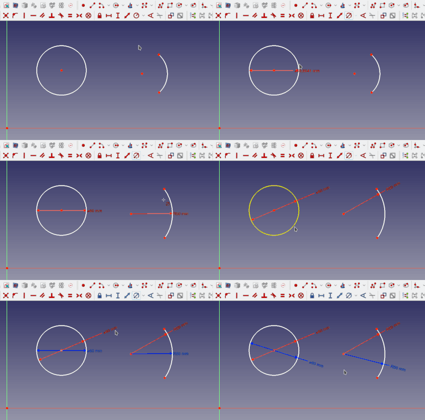
|
New |
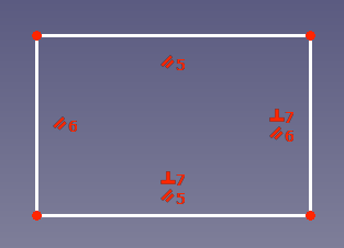
|
New |
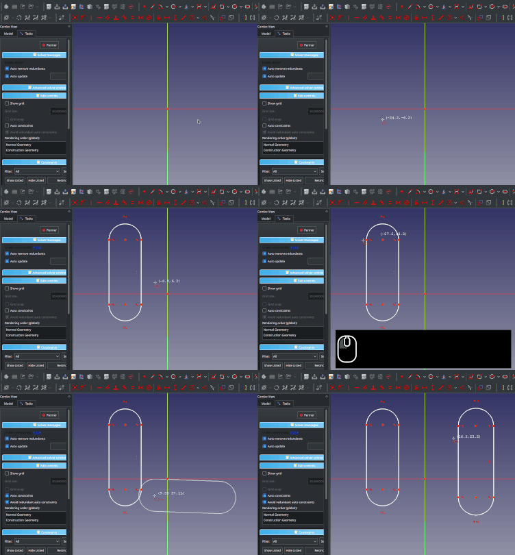
|
Slots can be constrained horizontally or vertically either by snapping it manually with the Ctrl key, or by using the Auto constraints option of Sketcher. |
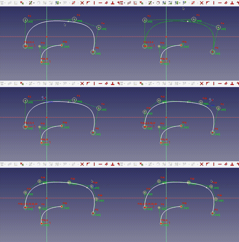
|
New |
Further Sketcher improvements
- Refactored Trim support. Pull request #4330 Forum discussion
- The behavior of the
Slot tool has changed. Slots can now be created by defining the center of both semicircles. Pull request Forum discussion
- Visibility automation allows to open Sketcher in Section mode when entering edit mode. Pull request #4742 Forum discussion
- Visibility automation allows to force camera in Orthographic mode when entering edit mode. Pull request #4778 Forum discussion
- Option to display the dimensional constraint name and use a custom format for it. Pull request #4966 Forum discussion
- When sketching a 3-point arc with Autoconstraint enabled, tangent constraint is proposed for all 3 points when hovering a line/curve. Pull request #4945 Forum discussion
- Radius/diameter constraints are displayed using an angular rotation to ease visualization. Angle and optional randomness are user settable through parameters documented in Fine-tuning. Pull request #4934 Forum discussion
- It is now possible to fix the angle of the direction when using the Rectangular array tool. commitc9eaa239 Forum discussion
- It is now possible to fix the angle of the direction when using the tools Clone, Copy and Move. commit Forum discussion
- By right-clicking a sketch in the Tree view you will now get a context menu entry "Attachment editor" that opens the Attachment dialog to modify the attachment. commit c3511ba2f0
- Constraint selection is disabled when using a geometry or constraint tool. It can also be disabled manually at any time by pressing Shift key. Pull request #5398 Forum discussion
- A versatile view filter has been added in the Sketcher task panel to ease constraints visibility management Forum discussion
- It is now possible to set the degree of a B-Spline (Pull request #6463) and undo the last defined control point (Pull request #6476) at creation time.
- Revised the default shortcuts to remove conflicting shortcuts and make shortcuts easier to remember. Forum discussion; Screenshots of the shortcuts for constraints, geometry and various tools
Spreadsheet Workbench
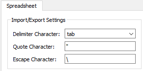
|
The workbench now has |
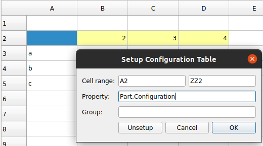
|
It is now possible to setup configuration tables. This way one can define different parameter sets for the same part.
Part of Pull request #2862. |
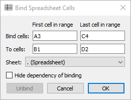
|
Cells can now be bound to other cells of the same or a different spreadsheet.
Part of Pull request #2862. |
Further Spreadsheet improvements
- In the row/column context-menu it is now possible to specify the position when inserting rows/columns. Pull request #4704.
- Import XLSX (used by Std Import): Added support for floor and ceil functions. Pull request #5015.
- Improved navigation using the Tab and Enter keys.
- Improved interface for cutting and pasting blocks of cells.
TechDraw Workbench
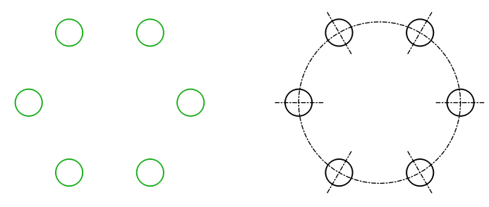
|
More than 30 new tools, so-called Extensions, are now available. They offer new cosmetic features to enhance drawings. |
Further TechDraw improvements
- It is now possible to Share and Move Views between pages.
- When there are several Pages and a View, ProjectionGroup etc. is added, there is now a dialog to ask to what page the view should be added. Pull request #5309.
- A new format specifier %w was added to print the given number of digits after dot and remove any trailing zeros. Pull request #5401.
- The new %w format specifier is now the default. And the format specifier preference was moved from the Advanced tab to the Dimension tab. Pull request #6504.
- Flipped diagonal hatch was added for the Geometric Hatch tool. Pull request #6429.
- There is a new option to show a grid in a page. Several related preferences have been introduced. Pull request #6465.
- The unit display in dimensions was fixed according to standards. The degree symbol is always present for the dimension value and tolerances, other units only appear if ShowUnits is set. The unit appears immediately after the dimension value unless there is a tolerance, then it appears after the tolerance. Pull request #6581
Web
Qt WebEngine is now considered the default option instead of Qt WebKit.
External workbenches
Note: these are the new workbenches created in this development cycle, or older workbenches that received updates. See external workbenches for more workbenches that can be installed, and which cover a wide variety of topics. If you want to see your workbench added, join the forum and present your code.
A2plus
Several features to view, inspect and edit existing constraints were added. One can now e.g. highlight constraints with a label, suppress a constraint temporarily or run the solver only for a particular constraint.
For more information see the constraint handling description.
Assembly3
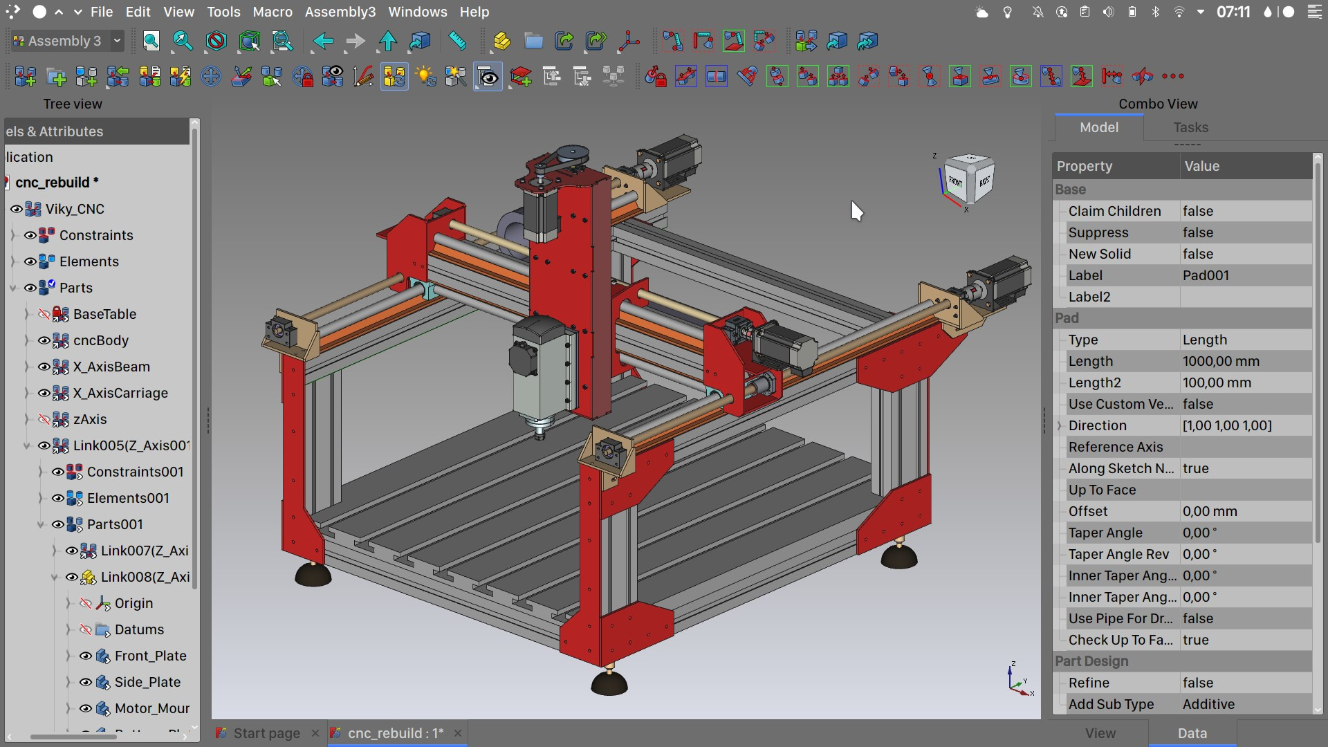
|
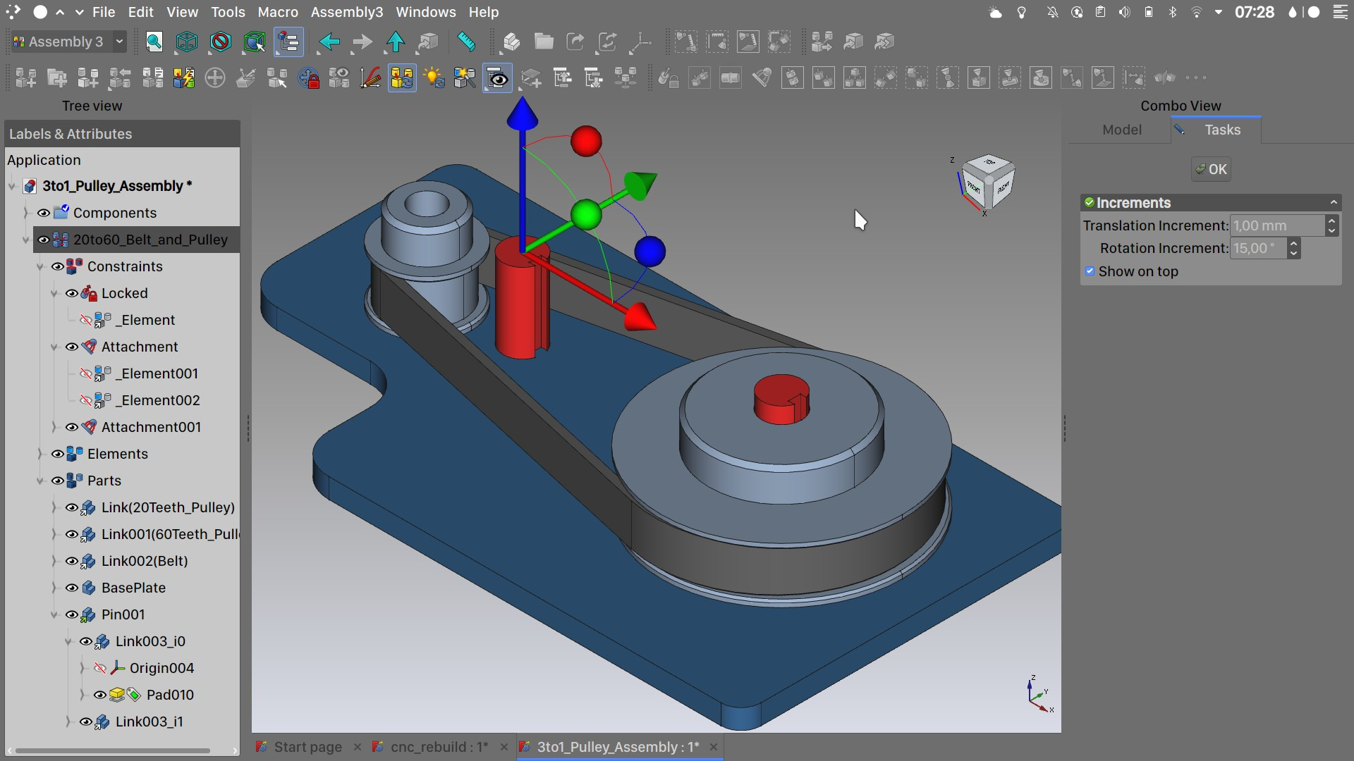
The Assembly3 Workbench is available (as of March 2022) through the AddonManager. This makes for easy installation and management of the external dependencies of the workbench.
Assembly3 is used to create assemblies of different bodies contained in a single file or in multiple documents leveraging the full power of FreeCAD’s Link system. Learn more about Links in this video presentation from Realthunder. Assembly3 Workbench uses SolveSpace as it’s solver. Extensive documentation can be found at the main FreeCAD Assembly3 wiki page or Realthunder's GitHub Assembly3 wiki |
|
Main features:
|
Assembly4
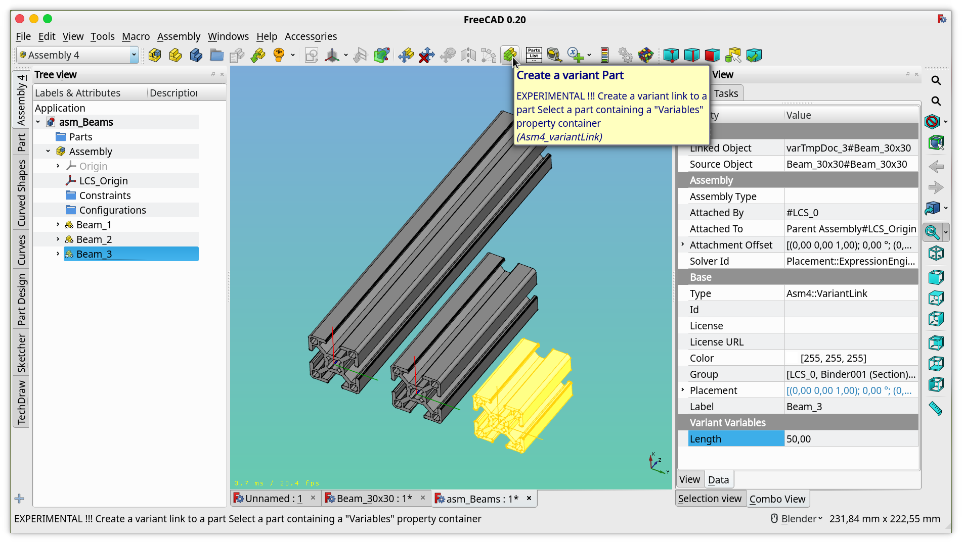 Different length of a beam as variant. |
New feature to add variants. These are links to a part with varying parameters, meaning that you can insert the same part several times, and adjust the parameters of each instance. For more info see this forum thread. |
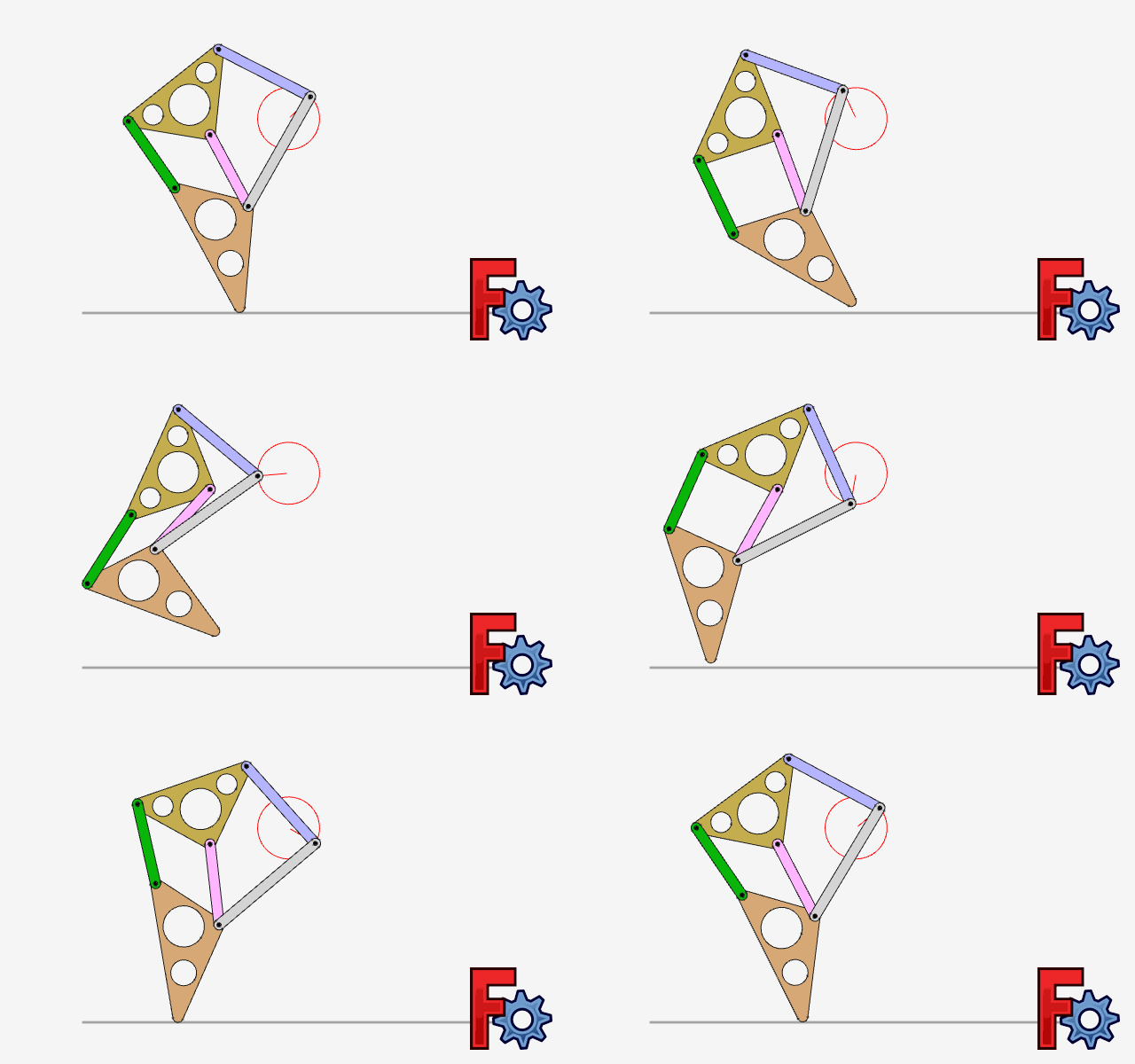 An animated assembly. Click on the image to see the animation. |
Animations can be exported to the MP4 and GIF format. |
FCGear
The FCGear Workbench received a couple of improvements:
- For involute gears, the outside (aka tip) and root diameter are exposed as properties (details).
- Gear objects are now attachable (details).
- Gear objects can now be used as additive features in PartDesign Bodies (details).
- The creation of gear objects now appears in the undo stack (details).
Plot
- The Plot module has been stripped from the Plot Workbench since it is now provided by FreeCAD.
Ship
The Ship Workbench is back to life!
- A new tool to compute the static sink and trim has been added.
- A new tool to compute the response amplitude operators has been added on top of capytaine.
Compilation
Since this release FreeCAD can only be compiled using Qt 5.x and Python 3.x. The lowest supported Python version is 3.6.9 according to this forum thread.
The supported operating systems are:
- Windows 7, 8, 10 and 11
- Linux Ubuntu Bionic Beaver (18.04) and Focal Fossa (20.04)
- MacOS: 10.12 Sierra or newer
Known Limitations
32-bit Windows
Since FreeCAD 0.19 we no longer officially support 32-bit Windows. FreeCAD might work on these systems, but no support is given.
Remote Desktop under Windows
Depending on the OpenGL graphics capabilities of a computer, it might be that one encounters a crash when running FreeCAD via remote desktop. To fix this upgrade your OpenGL driver. Only if this doesn't help:
- Download this OpenGL library for 64bit Windows and extract it.
- Rename the DLL file to opengl32sw.dll and copy it to the bin subfolder of FreeCAD's installation folder (overwrite the existing DLL there).
MacOS: Start Workbench shows blank page
If the Start Workbench shows only a blank page, you must enable the option Use software OpenGL in the menu Edit → Preferences → Display.
